Today was a wonderful day filled with little round things.
I’ve begun working on Ãœberclocker’s minor parts as I await another run on the waterjet (and more aluminum) to finish the fr0k. This is slightly more work than I anticipated, and with my days taken up by both the Media Lab and the MITERS-alumni-generated giant-solar-mirror-squeegeebot-building startup, free bot time is actually getting fewer and farther between. There’s nothing meaningful at that website yet. However, should you need giant squeegeebots for cleaning your multi-square-metre shiny, smooth surfaces later on, please give us a ring.
Here’s a completed “front leg” assembly, composed of two waterjet-cut pieces and some standoffs. I have become a fan of the “2D assembled shapes” building method since most of the work is done by the waterjet cutter. I only had to countersink the side plates (and a good 5-axis waterjet can even do that o_O)
With the new tooling setup on the lathe, I can make a simple standoff in under 30 seconds. A screw machine can do this in under 3 seconds, but I’m also not making 10,000 standoffs in a single breath.
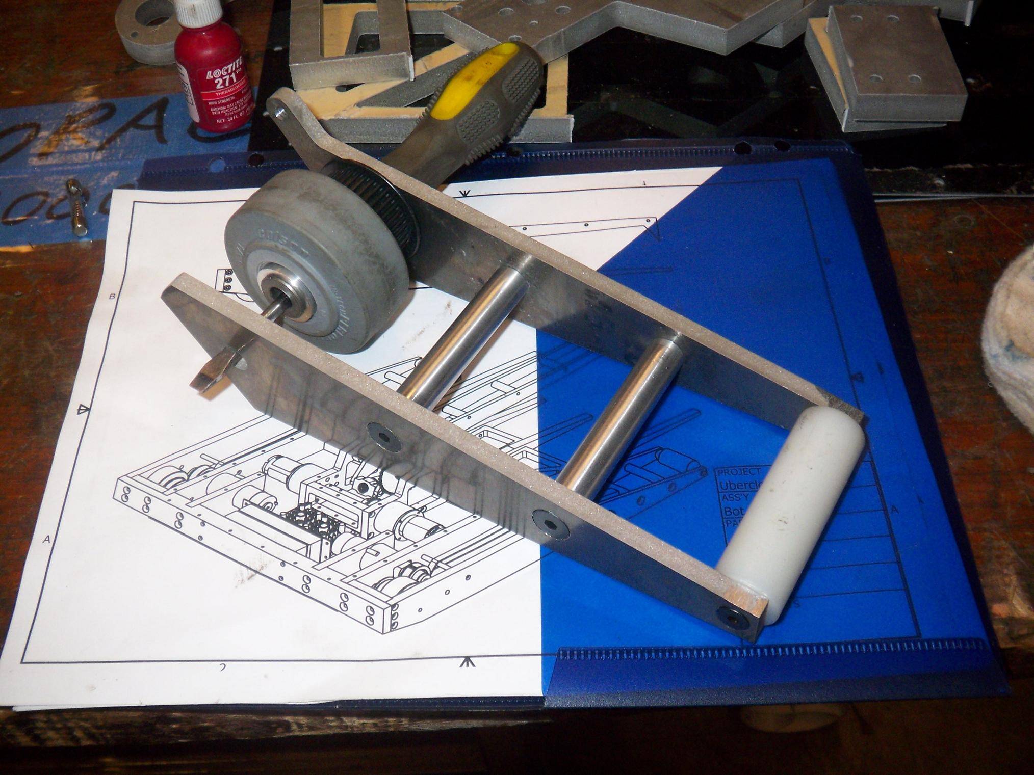
The corners on this will probably be chamfered inwards later on in order to allow traversing of the Robot Battles stage. The plastic roller is 1/8″ smaller than I intended since a 7/8″ UHMW round was sitting in a bin, but I would rather it be slightly smaller than dragging on the ground constantly.
I’m beginning to get a sense of how absurdly huge Uberclocker is going to be.
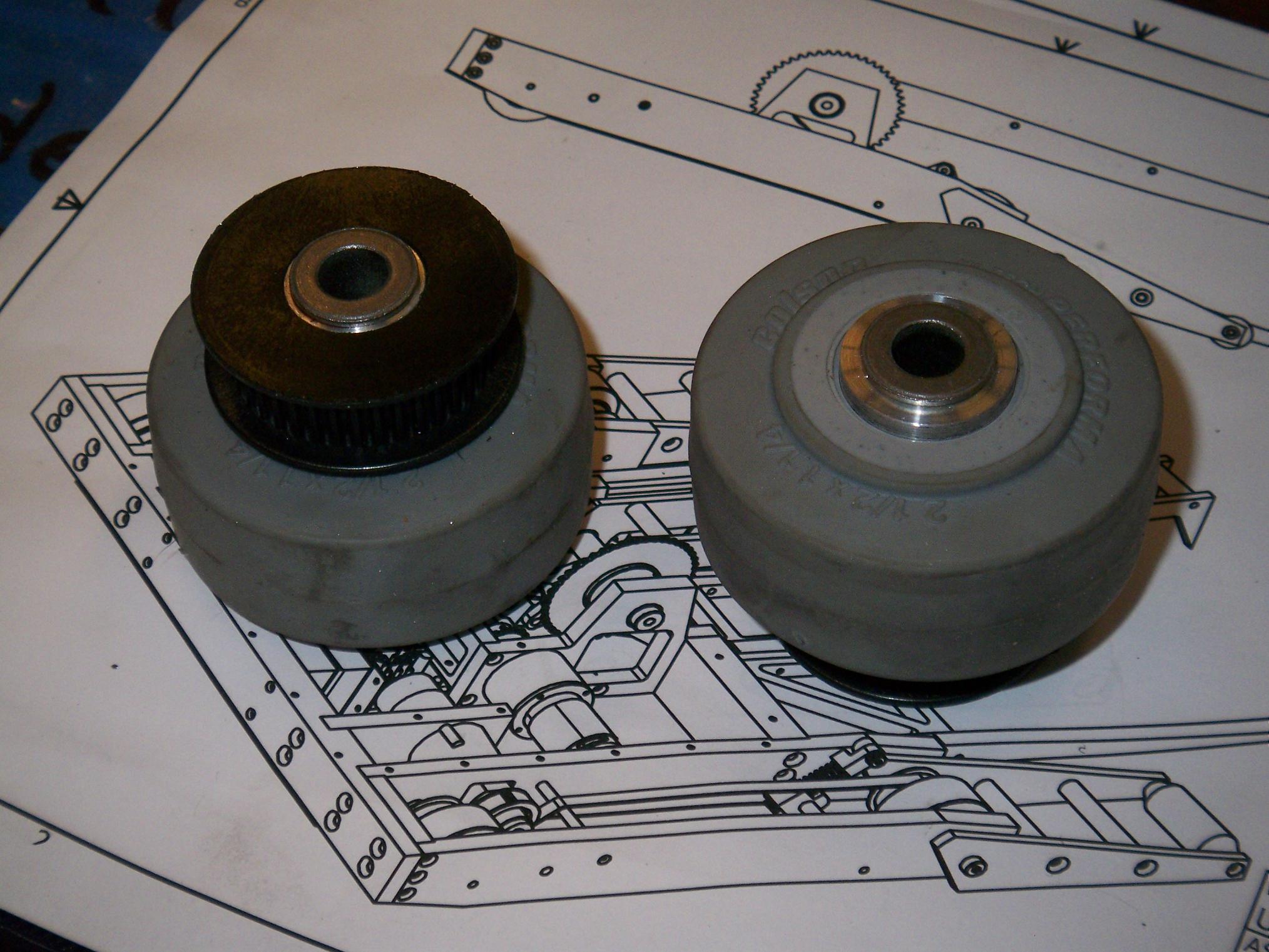
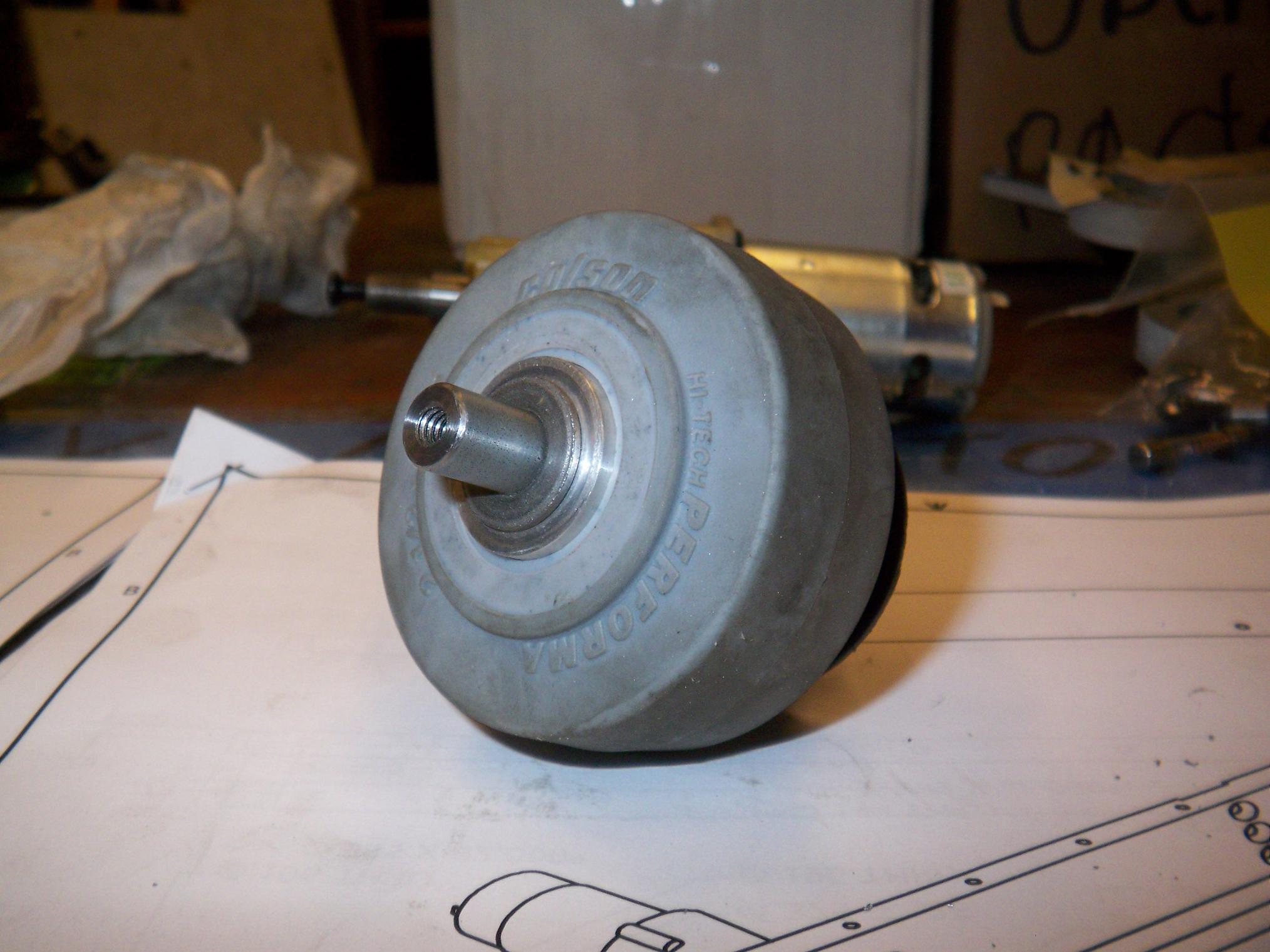
Next up were wheel hubs. The front and rear wheels are identical this time, being indirectly driven. I also cored out a pulley for each hub. 2.5″ Colson wheels press directly on the hub OD, and little bushings fit on the ID.
I remember when making little round things like this was a OMG SRS BIZNESS and took 40 miles of driving and all day to do. Oh, wait, that was last year…
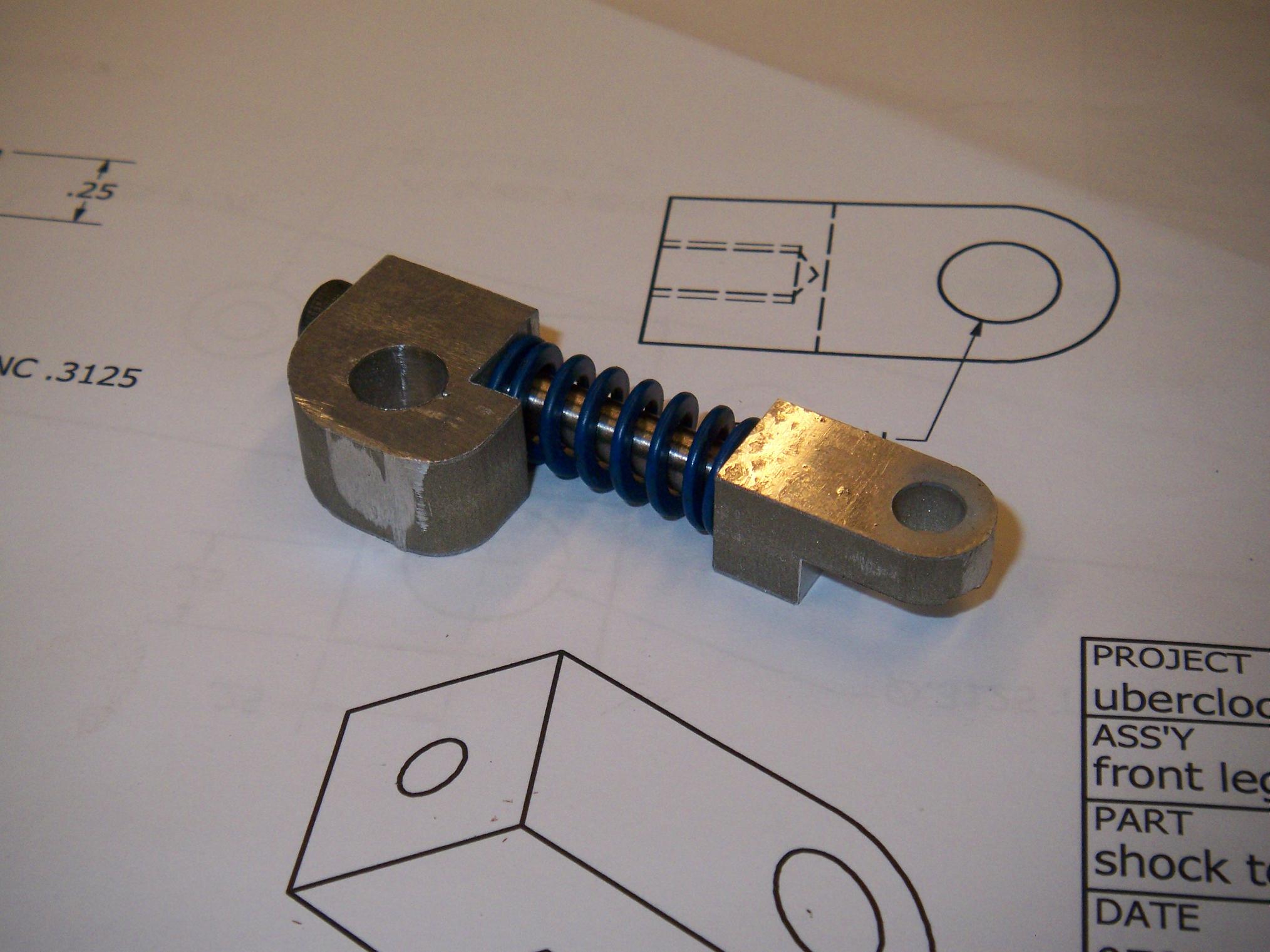
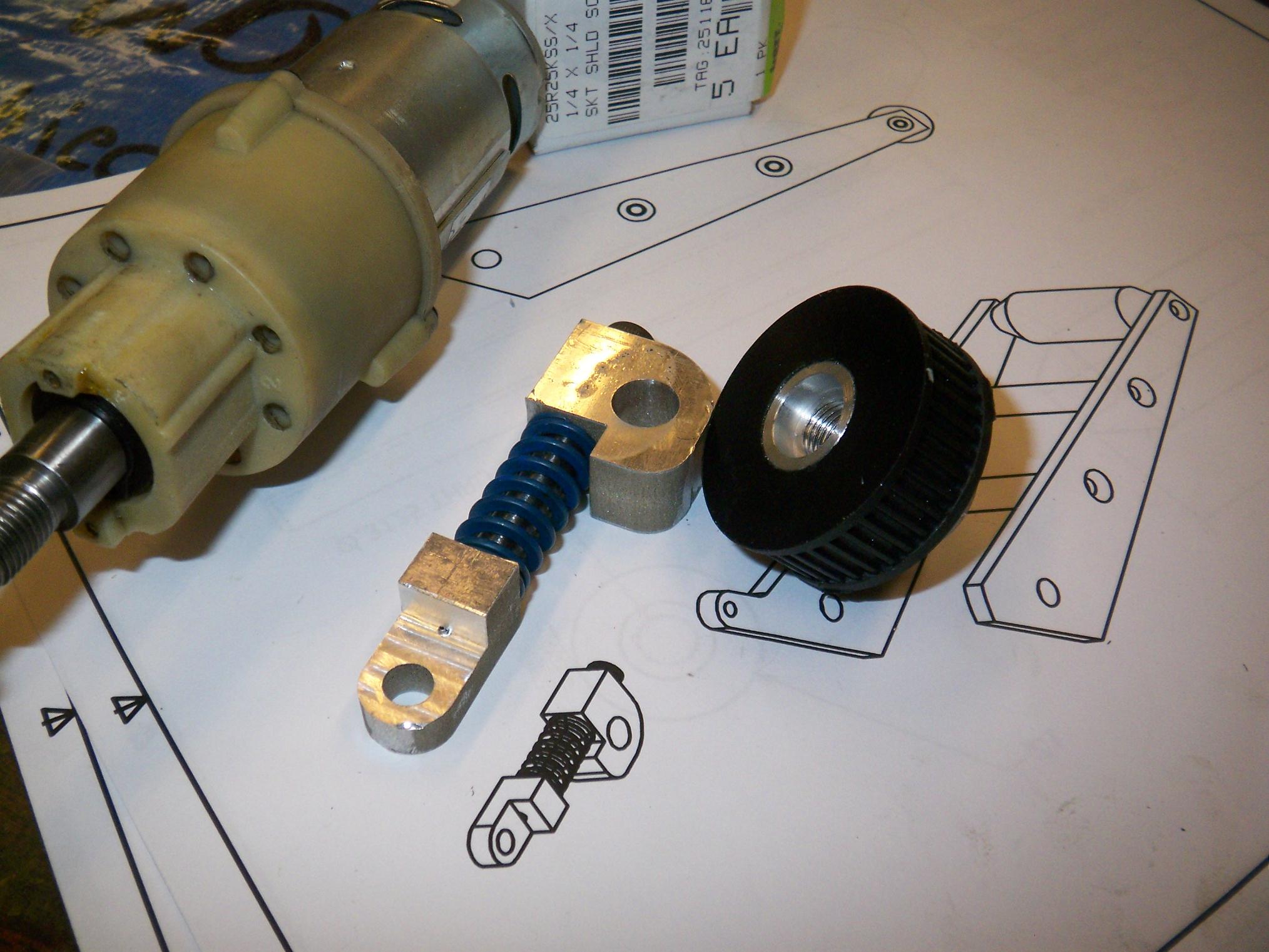
Here’s a completed “coilover” thingie. I’m really not sure what to call it – it’s not a shock absorber of any sort, just a springy plunger thing.
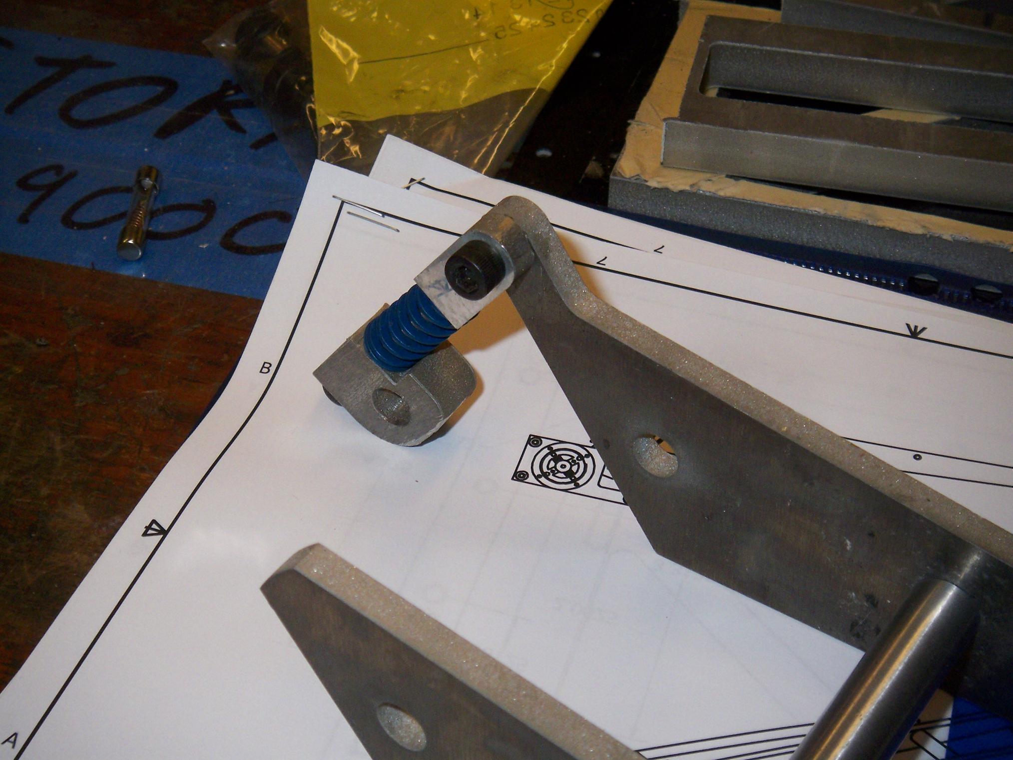
And it latches onto the front support accordingly. The back end will be fixed to the frame and the front supports will float freely on an axle. The spring allows for compliance with the floor obstacles at Robot Battles, but when the bot raises an opponent, they will deflect more and push back with correspondingly more force, hopefully allowing the bot to balance. I can upgrade to stiffer springs if they prove to be too weak.
I also made a motor-side pulley with hub. The drive belt on each side will wrap around all three pulleys and a tensioning roller in a serpentine configuration. I have yet to design a belt tensioner, since I don’t know exactly how long the belt needs to be, and ordered a pair just based on the combined pitch lengths of the pulley system.
The cored-out pulley presses onto its own aluminum hub which is threaded on the inside to mount on the drill motor output shaft. I managed to fuck up this part twice – once by drilling through the wrong side and the other by mistaking a diameter for a radius and cutting twice as deep as I needed to.
Fortunately, MITERS is resplendent in 1″ aluminum rods.
I now have an appreciation of free-machining steels.
Here’s a completed axle-standoff, made from 3/8″ steel. They’re threaded on the ends so screws can attach through the frame and lock the axles in place while holding the frame apart the right distance.
I had to make this part twice also – the first try was with some 3/8″ “printer rod”, which is a sort of weird medium-carbon steel. This must have been a serious printer, because the rod was actually case hardened and uber-polished.
Meaning: No tools I had could touch the thing radially. I actually had to cut off a 3″ section on an abrasive saw to begin machining.
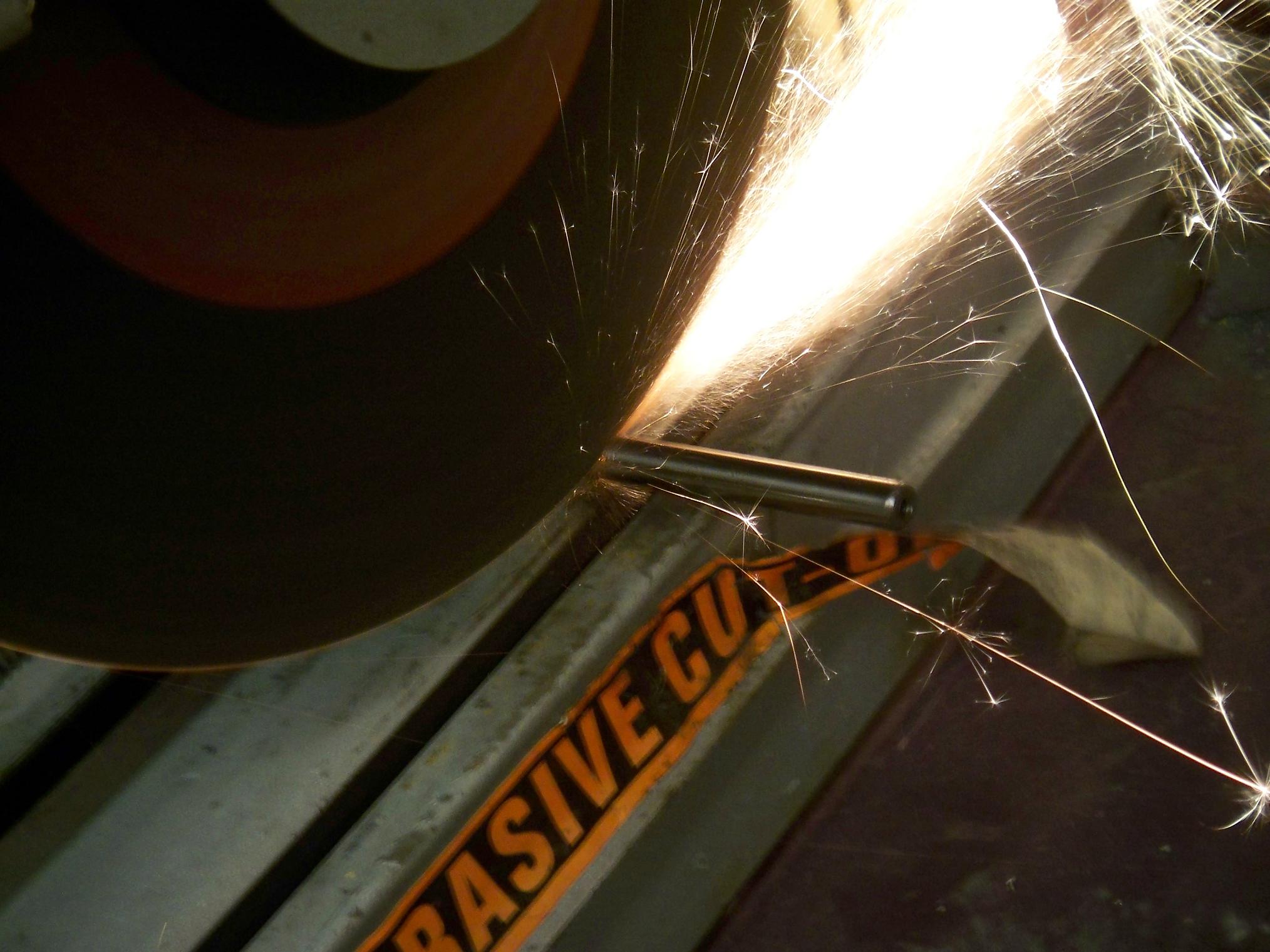
…like that. This is a nice picture, too. If you like long-exposure shots of burning metallic compounds, also check my Fiarwørks Day picture album.
Regardless, even after that, it was still an enormous pain to face to the correct length, chipping the tip off one of the HSS bits (a quick regrinding brought it back to life). It also ate a drill bit I tried to end-drill it with.
I gave up on that and dug around for some better material, and came up with a 3/8″ cold roll steel rod, which went quickly and quietly. CRS not being much stronger than 2024 aluminum, I wondered why I didn’t just make it with an aluminum rod.
…right, because aluminum galls like a motherfucker. A dash of 400 grit sandpaper to the 3/8″ steel rod and the wheel slipped right on.
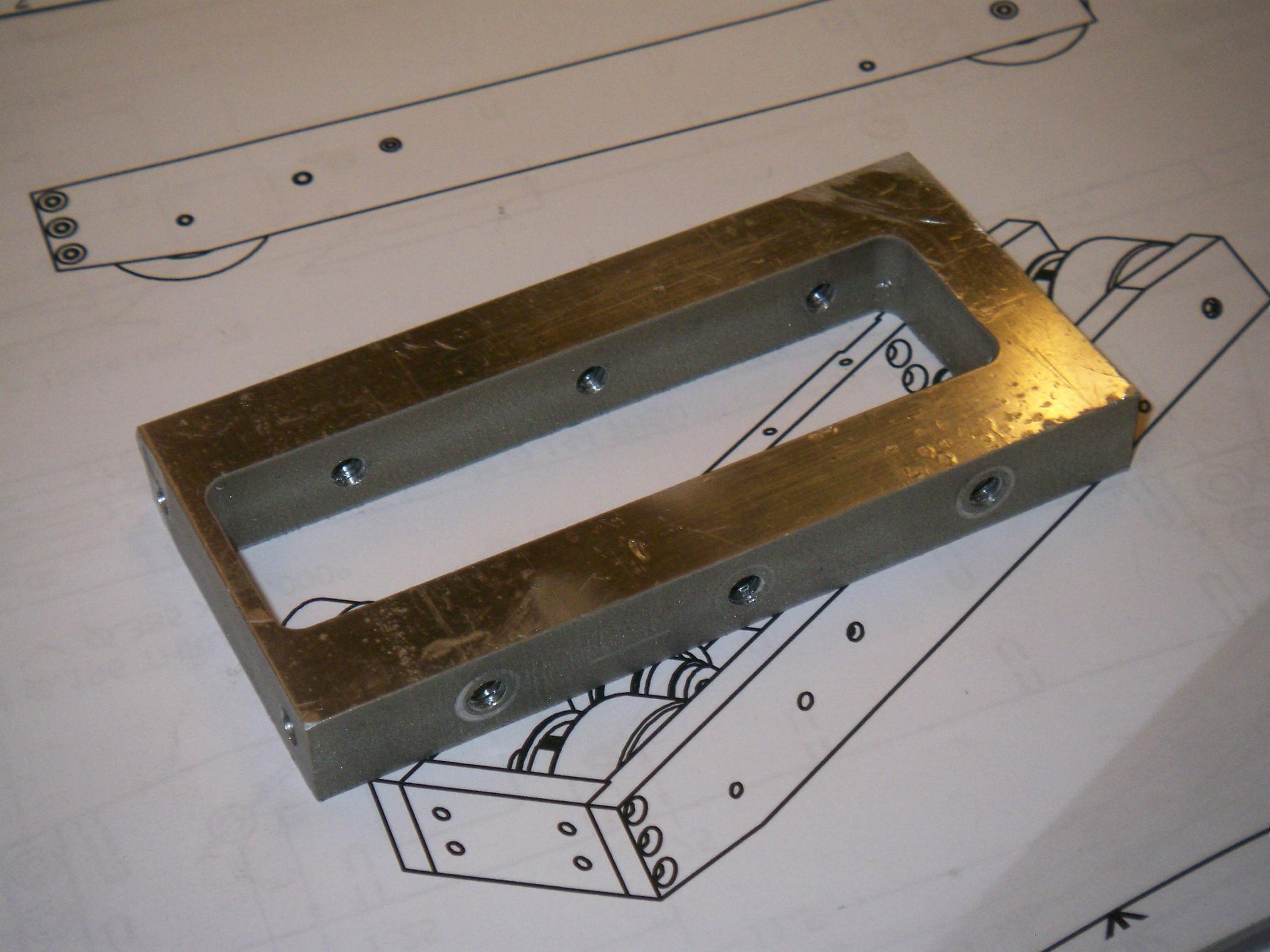
Lastly, in non-round-thing adventures, I finished processing a part of the fr0k assembly. This is the rear “connecting block” between the two arm towers, and was one of the few pieces that I could still salvage from the ill-fated 1/2″ aluminum plate. The reason is because nothing critical is actually on the front face of the part.
Double-sided features on parts are a pain, since I had to flip the thing over and re-zero everything to make the holes on the opposite side.
Stay tuned for more!