Revenge of the Chuckranoplan

It’s been nearly a year since my first visions of the Chuckranoplan.

Last time, knowing absolutely nothing about aeronautical design and lacking the funds and the testicular fortitude to just beast it, I decided to put off the thing until I became more familiar with the subject at hand and the physics and principles which govern ground effect flight. That, and I have no clue how to build something with surface curvature along more than 1 axis at the same time. Aircraft and boats don’t seem to be amenable to t-nutting, and that’s a problem. Somehow, I get the feeling that waterjetted aluminum plates and machined billet isn’t the way that most small watercraft and aircraft are manufactured.

Now, months later, I still knowing nothing about aeronautical design, but I do have a 3d printer. I’ve also been researching GEV design as a background process, and kind of have an idea of how this is supposed to work. But, overall, I’m still without a means… intellectually, that is, to build a person-carrying craft.

So then why not start smaller? If the vessel is sufficiently small, I could print parts or templates for it. Many times. In short order. Design validation via model testing is a totally legitimate method of making sure your transport implement works before it goes off and kills dozens of people changes the way people think about getting around becomes Youtube-worthy. Besides, making a small model Chuckranoplan means I will finally be able to use Hobbyking parts for the purpose they were intended.

And so with a fresh install of Autodesk Inventor 2011, I hopped in and started playing with the more advanced geometric features I haven’t looked at before.


That’s when I discovered that my knowledge of Autodesk Inventor was really, really, really pitifully small. It’s enough to make stuff… but not, say, smooth stuff, or good-looking stuff. I seem to have designed myself into a corner with my Chinese puzzle building methods.

Without further ado, here’s μ-Chuckranoplan.

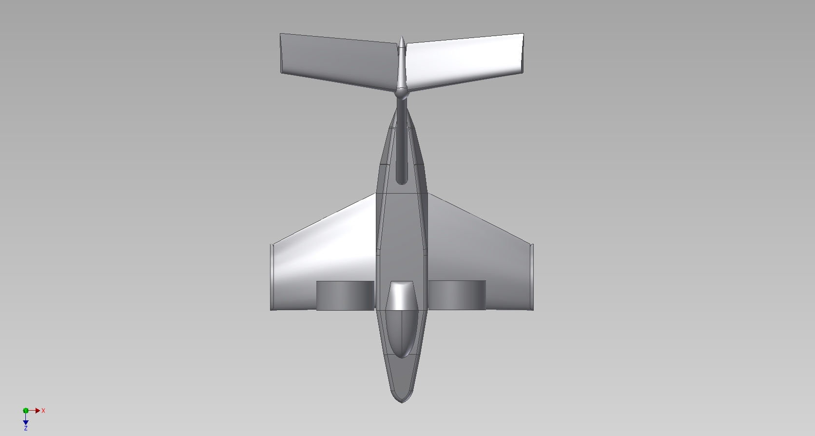
Hey! It’s kind of cute, isn’t it? I think I was trying to design both a conventional ekranoplan and a Lippisch-style delta wing at the same time, and succeeded in doing neither.  For clarity, forward is down.

I discovered that either I’m doing it way, way wrong (more likely), or Inventor isn’t as well suited to smooth surface modeling as a program more geared towards animators and industrial designers such as 3DS. Basically, making the hull and airfoil profiles were a royal pain and very time consuming using multiple lofting operations. What made it worse was that while I had a nice airfoil profile picked out using Javafoil, I couldn’t get the sketch point import to function at all. I believe it’s a matter of Inventor wanting Real Microsoft Excel, not my Fake OpenOffice Not-Excel application.

So what does that mean? All the airfoil profiles on this thing were freehanded using splines until they looked right.

Yeah. Very scientific. But I think they’re okay.

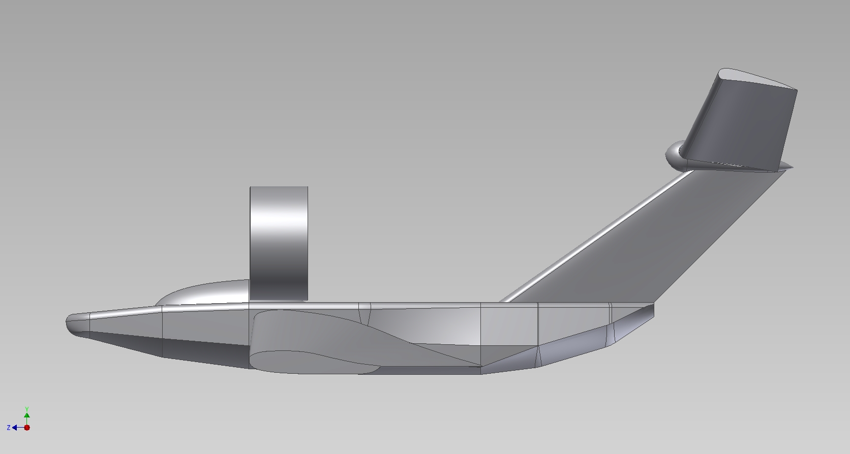
Here’s a side view of the design. The cylindrical blocks are stand-ins for some small 30mm-ID ducted fans I found on Hobbyking. I won’t be able to design the pylons or really even the shape of the things until I have them. While I would have pursued front-mounted fans (for PAR and badassery), putting those huge ducts in front of the “bubble” made the whole thing look incredibly derpy.

I already think delta-wing craft look derpy, so my design goal here was lessening the derp.

Such being the case, I’ve temporarily designated the twin fan location as immediately behind the “cabin” area. I haven’t done any fluid flow simulations, but I think they’re sufficiently out of the way of the main wing top surface.

They give the thing a mouse-ears effect, which makes it even cuter.

In this view, you can clearly see my utter failure at hydrodynamic design. I’m fairly certain the hull should actually be turned around – fatter at the front than at the rear, so to speak. Making all those loft profiles come together was also difficult. And of course the way I did it ruins any chance of making the craft body a continous smooth surface.

The model, when assembled, has a wingspan of 9 inches, a length overall of 12.25 inches (tip of nose to highest tip of tail in the very back), and a height of 5 inches. Since I’m limited to a print area of roughly 6″ x 6″, I can’t fire off the entire thing at once. The model is actually an assembly split into a few large parts. Each wing is separate, and the body itself is 3 pieces – the front nose portion, the middle (essentially the chunk from leading to trailing edge of the wings), and the back section. The vertical part of the tail, including the round thing, is another piece. Finally, each tail airfoil is separate. The interfaces will be made using inserted dowels and plenty of superglue.

It will be fun to test as a “throwie” model, but I’m going to print the segments as hollow shells to save weight anyway. Therefore, I can easily cut away a part of the outside to jam small flight electronics into it. The middle body cavity is probably the most amenable to this treatment. Incidentally, that’s where the center of gravity should be.

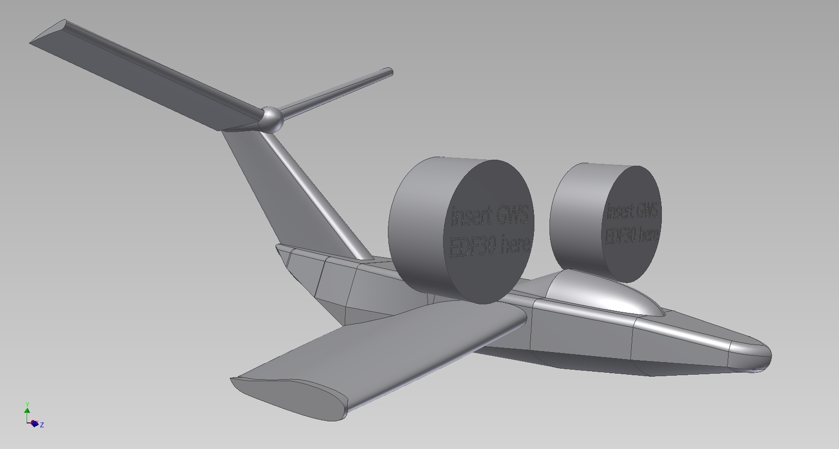
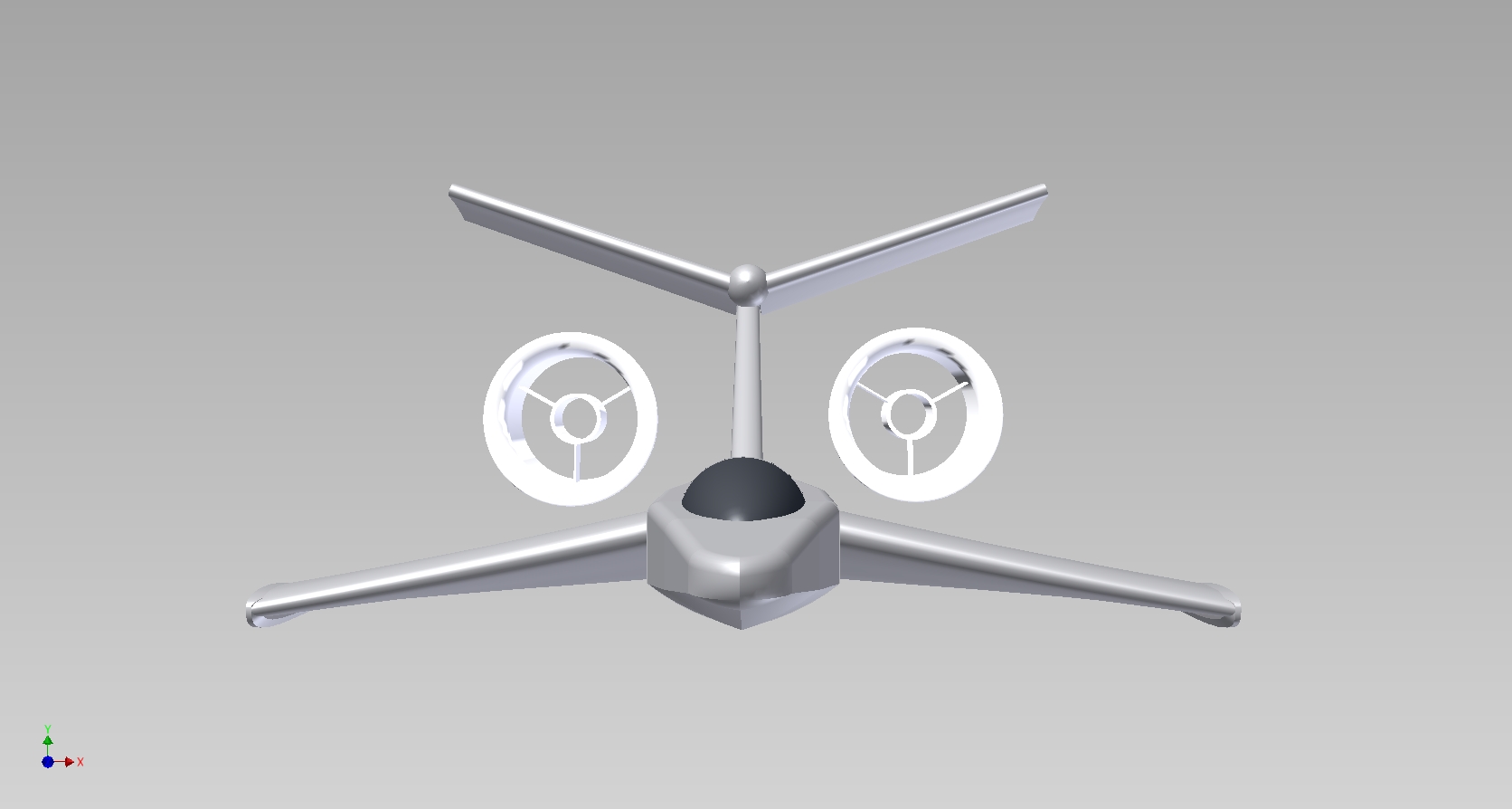
I’ve cleaned up the geometry a bit here, and also modeled the fan shrouds based solely on the Hobbyking product image. The only thing I know about it is that it’s 30mm inside and 40mm outside.

Note that this model has no control surfaces, because I’m not that sophisticated yet. So, the dual fans will also play a role in steering via differential thrust. For this reason, they might end up further out from the wing root, just for more leverage.

I’ve already tried printing one wing out of PLA plastic, and it turned out quite nicely. So I think I’ll just piece the rest of the model together as the week progresses and my HK parts arrive.

Oh, yeah, that was another criterion in designing much of the geometry – that it’s printable without support material. I think I did okay in that regard.

While my test prints will be in PLA since that’s what’s loaded into Make-A-Bot at the moment, I’ll probably order some white ABS plastic for more structural durability and impact resistance. Because I know I’m going to plant this right into a wall at top speed.

Hopefully in the near future I’ll become better versed in curved surface modeling, and the design will evolve. Then I’ll build one 40 times bigger.

Land-bear-shark Update 3: Listening to Charles complain about everything

I was wrong.

The metal didn’t come “that week“. Or, for that matter, the next, when I was in Singapore and therefore couldn’t do anything about it anyways.  After it all finished, my metal was delayed by a solid month. What was the vendor’s excuse?

I looked up your order and it seems yours and a
couple other orders that were supposed to get
shipped fedex never got printed out and therefore
didn’t get shipped out.

Right. Just like that. After an email asking for an update on the order (to no reply), and 2 more asking for a refund with the last being a ship-it-express-or-negative-feedback ultimatum (still to no response), the metal for LBS finally showed up on the 20th of January, of course shipped ground the week before. I’m sorry, you’re not gaining back the negative feedback point. For future reference, never, ever buy from this guy on eBay. The prices are low, but I could have ordered from Speedy Metals three and a half times over in the same period. Or got it made straight through Simon like 5 times, and not had to deal with excuses and silence. Next time I get anything from eBay, I’m staying on the seller’s ass so hard it’ll cost me the point.

So that’s why there’s not a Melontank at the moment. With IAP having ended, I’m faced with less time to hammer away on it as a whole. Luckily, the 8 miles or snow or so that’s on the ground shouldn’t melt until… I don’t know, July at this rate, so maybe I’ll get to climb a little hill or something soon. Assuming I pick up the pace and actually design the hands-free control – who knows, the first run might be me holding a R/C transmitter.

Alright, so here goes. This is roughly the span of the last week or so, which is when I had to play the wake-up-during-the-daytime game to get things cut.

As usual, we begin with the waterjet puzzle.

Wait – there’s actually more of a story to this. I had to rush-order another plate of 1/4″ aluminum from Speedy Metals (who lived up their name) because I wrote off an entire plate after trusting the OMAX autorouter more than I should. I’ll take this moment to complain some more – namely the autorouter software is the least intelligent thing I’ve ever had the joy of experiencing. I’m not sure what’s so hard about finishing one part before moving onto another, but it seems to revel in making cross-stock express runs right over previously cut features. So, no matter how closely you watch it, inevitably it runs into itself and bumps the piece. As a result, the entire coordinate system of the part becomes shifted mid-cut, and pretty much everything is ruined.

After losing that plate, I taught myself how to manually route files pretty much on the spot. The backup plate was cut without incident as I removed completed parts out of the tank one after another.

Come on OMAX, stop making your interns write the path software already. One closed external profile at a time.

Now that I’ve complained and bitched enough, here’s an elaborate waterjet-cut box.

The plates were cut with a .003″ closer offset distance such that most of the tabs and slots just fell together. However, I seem to have neglected to do that on the first plate (before I destroyed everything), so the bottom side panel in this picture is a really stiff hammer fit.

If you’re also intending to make things fit together on the waterjet, I’d recommend either reducing the tool offset a few thousandths or making your slots a few thousandths bigger and tabs a few thousands smaller, just so they slide together easily. For 1/4″ aluminum, 0.003″ inwards (i.e. total width of any kerf is actually 0.006″ larger) seems to be great.

The box is complete.

Well, minus a whole ton of hardware. I ran out of 4-40 button-head screws, so for now, this will have to do. I also seem to have physically lost the 1/8″ plates I cut out for the triangular things at the end between last week and now.

Since this project has gotten to the point where it can hold its own parts (hey, it is a box), I threw together this poser-shot. I think it’s pretty reflective of what the final vehicle will look like.

course 6

None of my excessively dangerous vehicles are complete without some kind of controls headache, and Melonsharktankbeargryllspigweek is no different.

In updates prior, I clearly showed the Melontrollers being mounted on the control deck. The fact of the matter is, I don’t think they’ll actually make it into version 1. Melontroller is not yet stable enough for me to put it on anything less benign than RazEr…which has already seemingly ate one controller. For once, it wasn’t in a fiery explosion, but the Arduino Mini just…. died. My guess is that a transient made it past the regulator somehow and killed it. It was also never really running a motor that smoothly, nor did I have the current sensors even mounted on the board. There’s also a ton of changes I want to make to the design to make it more noise-tolerant and robust… including ditching the chopped and screwed linear regulator feeding the logic supply.

Pursuant to the delay of Melontroller, I’m probably going to end up using some mini-Kellys and a custom signal interface board. You know, some electronics I can actually handle. There’s several obsolete KBS36051 units hanging out in the Media Lab ever since we switched the model Citycar to DEC boards.

While they’re advertised as “50 amps”, they really limit the phase current to about 20 amps continuously. On a stock 80xx “melon” winding, which is like 2 and a half turns of 4/0 copper busbar, that does absolutely nothing. Even if LBS was able to get up to speed, the motors are just too fast to work well with the current speed reduction – 5:1 on a motor that’s rated for 170 RPM/V and running at 42 volts still gets me over 35mph.

I don’t particularly feel like dying that badly, so I’m electing to rewind the two Melons to something more reasonable. Like, say, 18 turns of double #20 wire, Y-terminated, instead of the stock 8 turns of…. something… that’s Delta terminated.

By some crafty math, this should get me a motor with a RPM/V rating of about 40 (actual math: 170 original Kv * ((8 / 18) turns ratio / sqrt(3) Y-termination factor) ) With the as-designed 5:1 gearing, this will actually be quite tame at 15 miles per hour. The gearing can then be fiddled with. With the Y-termination and higher turn count resulting in increased phase inductance, the Kellys ought to freak out alot less than they did when I tried to run Melonscooter with them.

All that’s left for me to do is to design the interface to toggle the Kelly throttle, reverse, and brake inputs remotely. This will, again, probably be accomplished using some flavor of Arduino.