micro-chuckranoplan: how i know i’m not an aerospace engineer

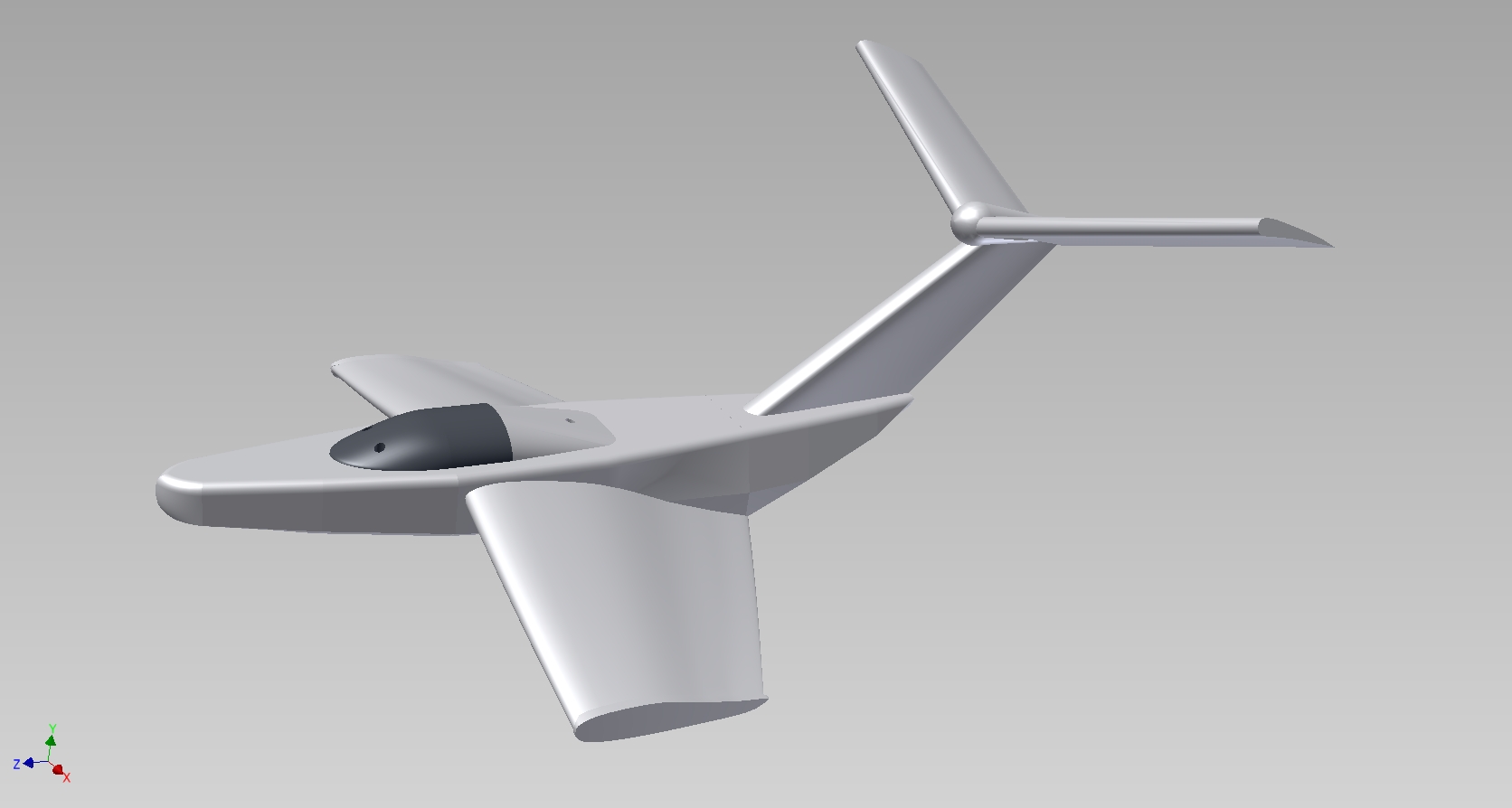
The verdict is in: μ-Chuckranoplan sucks. Well, I think design-wise it isn’t too bad, but it just weighs a ton. Specifically, the rear end is just too heavy for its airfoil size, despite being printed as a shell. The airfoils turned out to be too thin in cross section and printing them even as a shell made them almost solid.

It might do better as a 3 or 4 foot model, but certainly on the 9 inch scale, it’s too brick-like to glide. Maybe I should just take up crafting these things from foam.

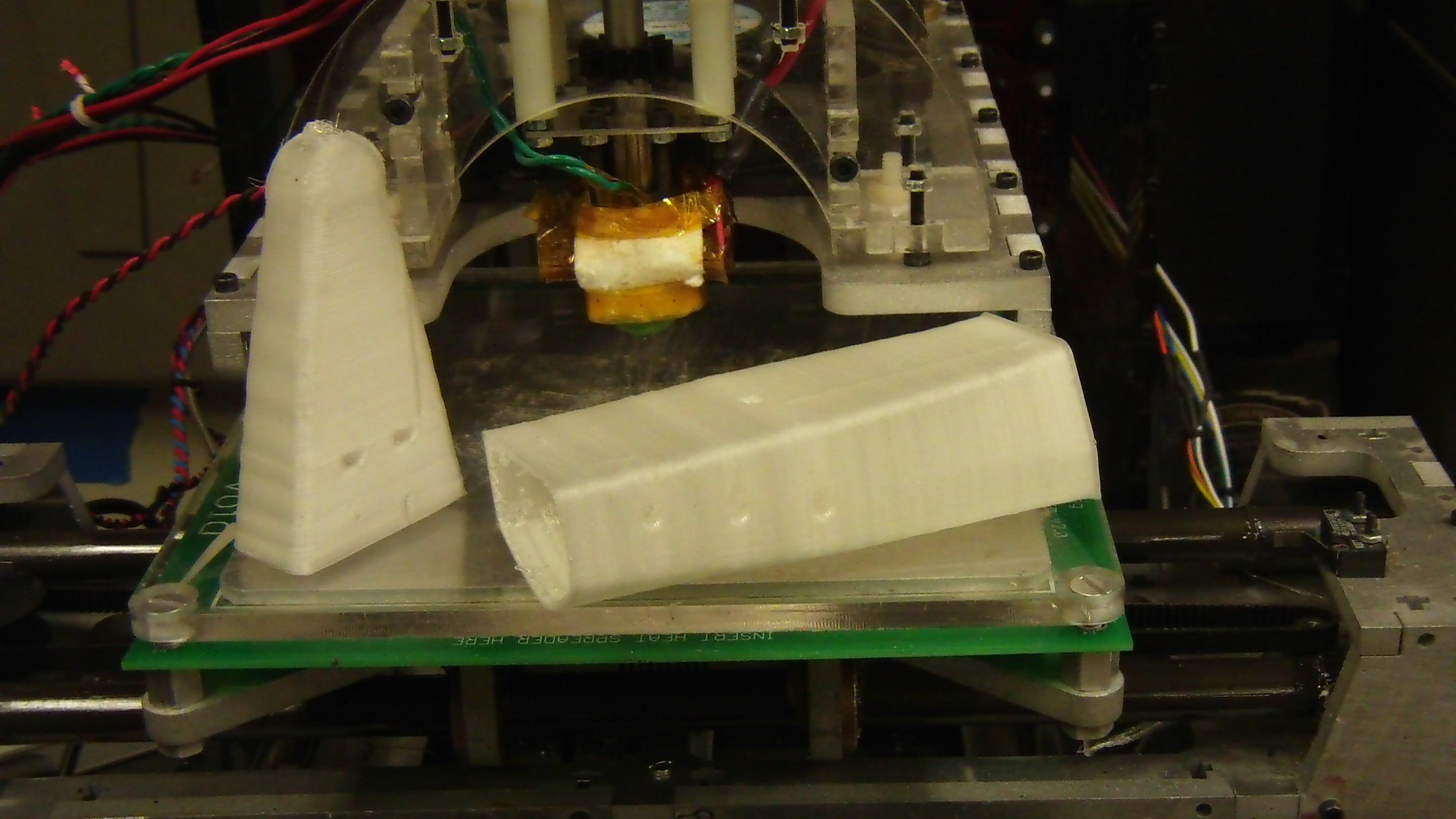
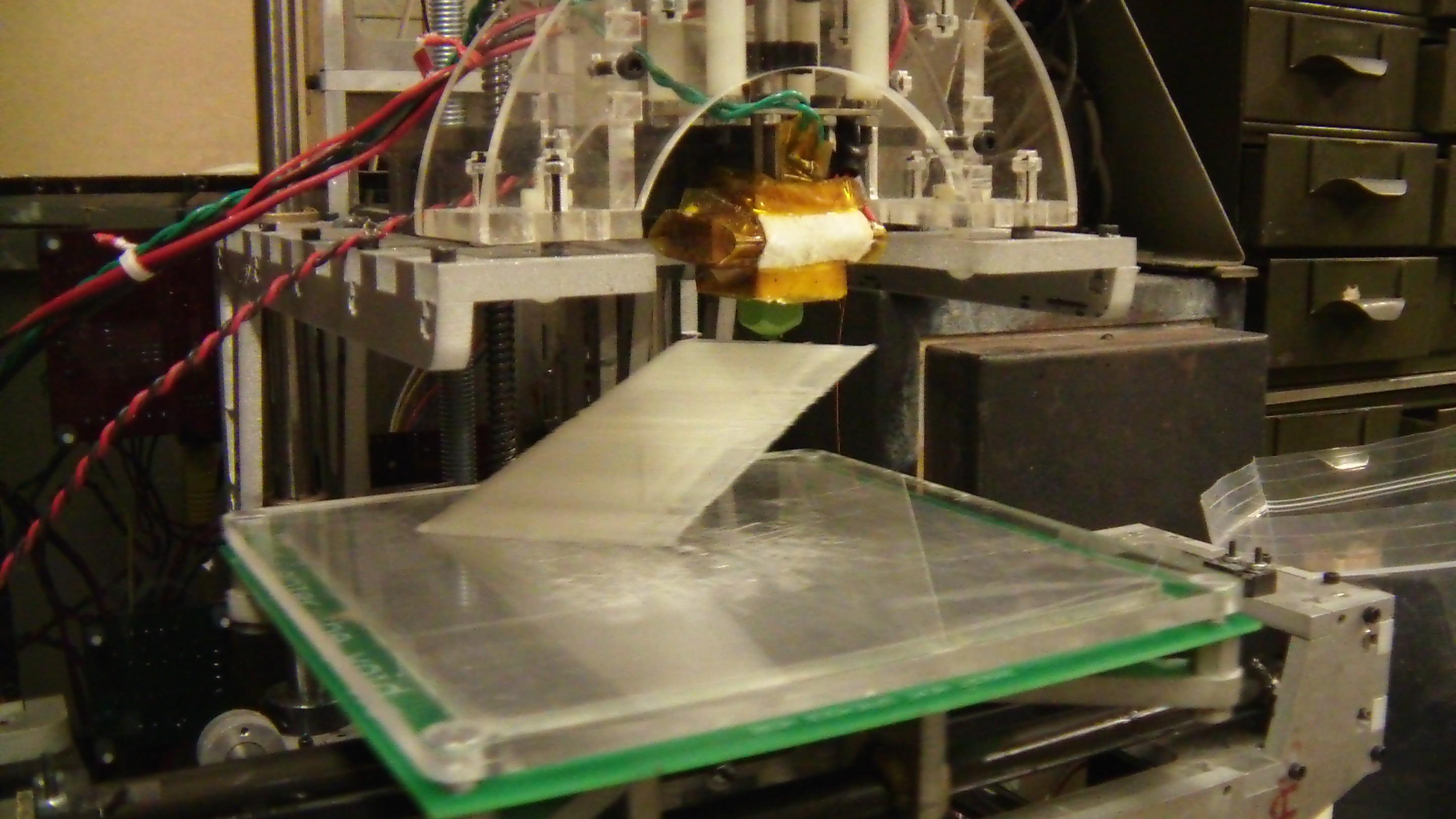
I elected to print the body and nose sections vertically as hollow shells. I discovered that printing them “flat side down” made the prints prone to corner lifting with their broad surface. Additionally, the extreme overhang angles that form the bottom of the hull led to very poor prints on a fully hollow shell, or caused the g-code generator to insert several fullly filled layers for support, which caused them to be too heavy.

Afterwards, I cut a solid end layer out of each half such that they could form a continuous cavity inside.

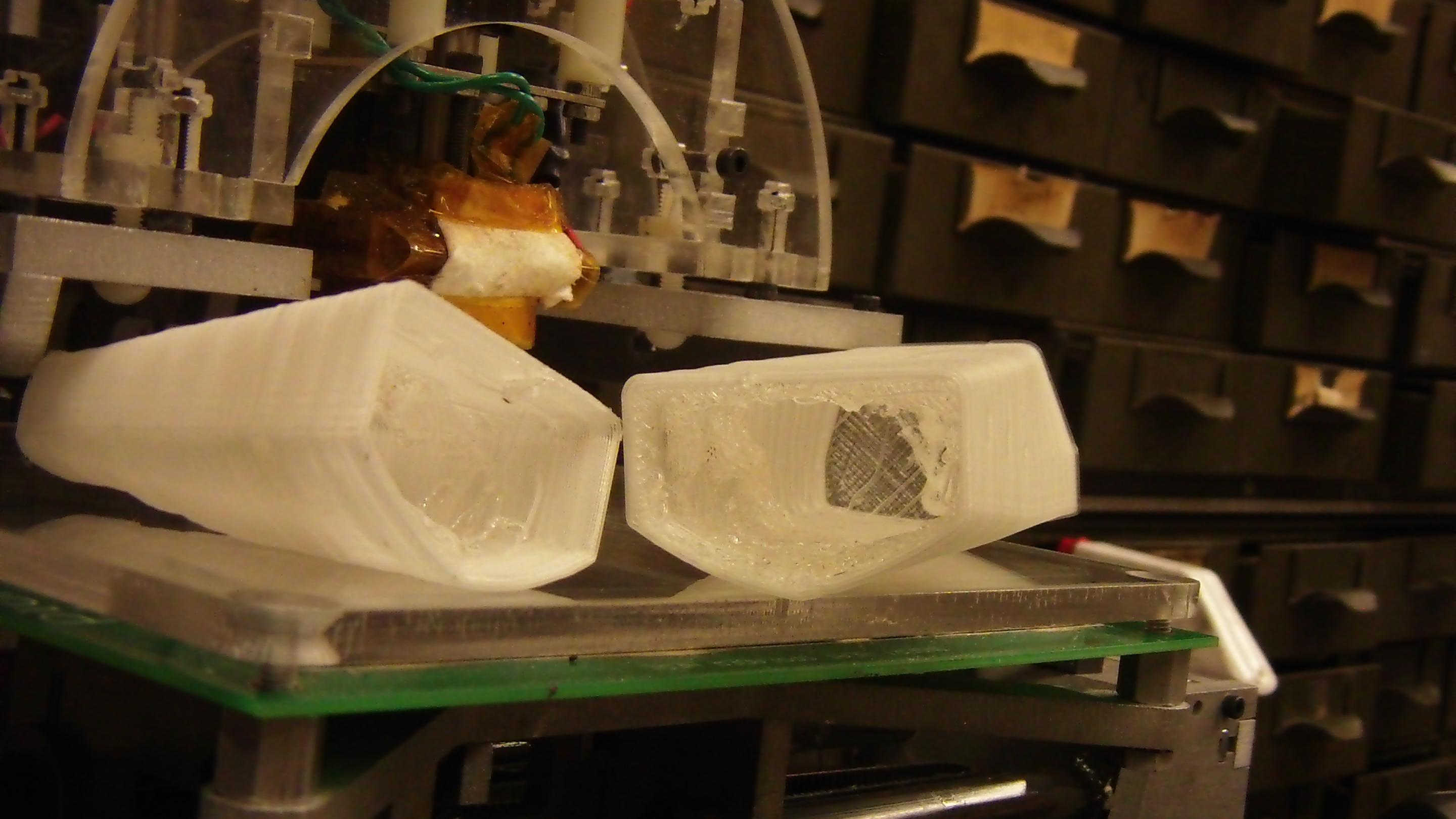
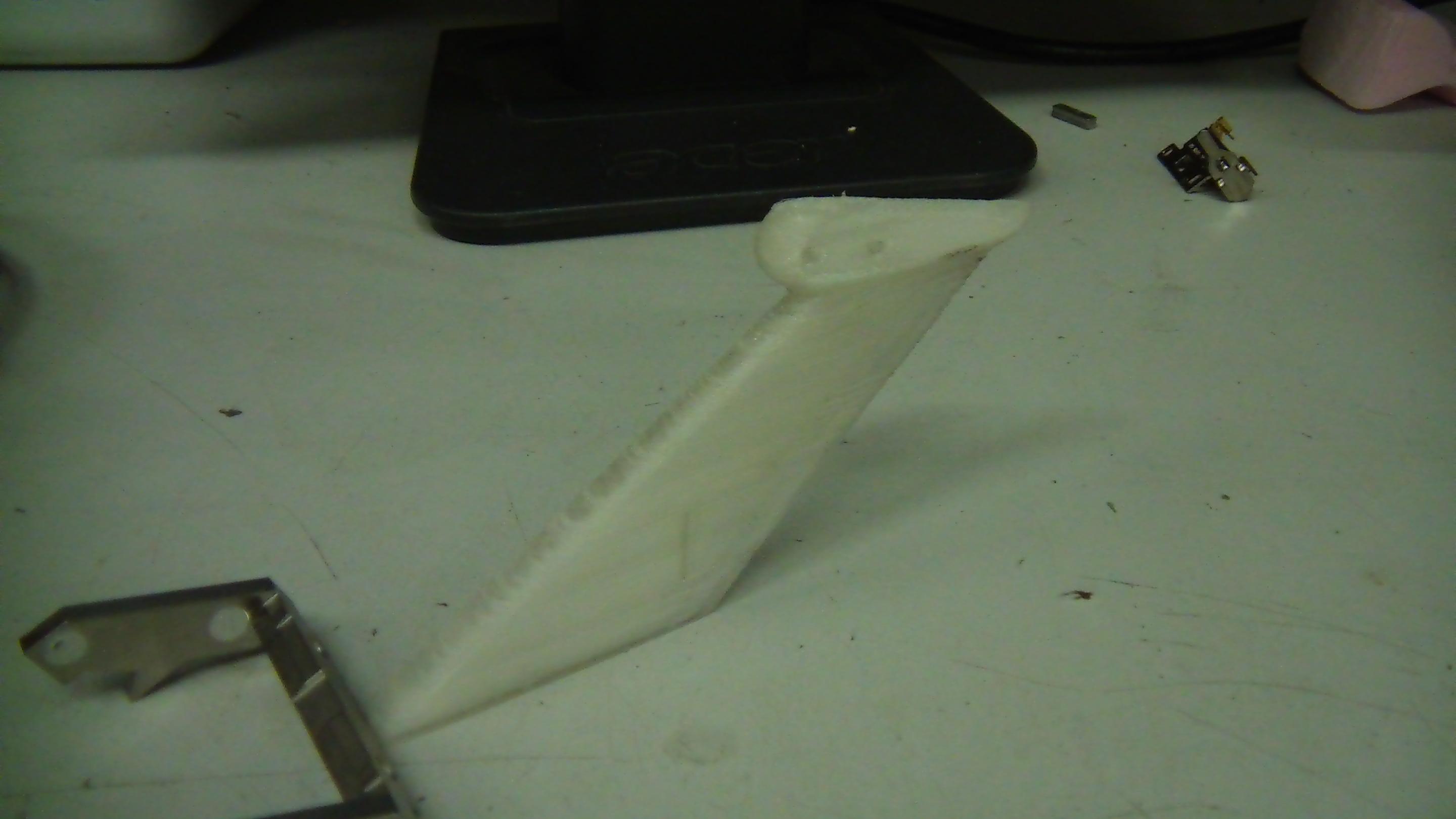
Despite my requests to print a fully hollow shell, I still received some halfassedly filled layers and lots of internal webbing. To get those out of the way as an anticipatory move for installing little lipos and motor controllers, I blasted the interior for a few seconds with a hot air soldering rework station set to 400 degrees C. This melted away the thin webbing but kept the outer shell intact. Detailing included scraping some of the melted webbing out with a craft knife. The two halves were then joined using some thin CA glue – Loctite 420, the kind that wicks into crevices, especially those formed by your finger contacting the part in question.

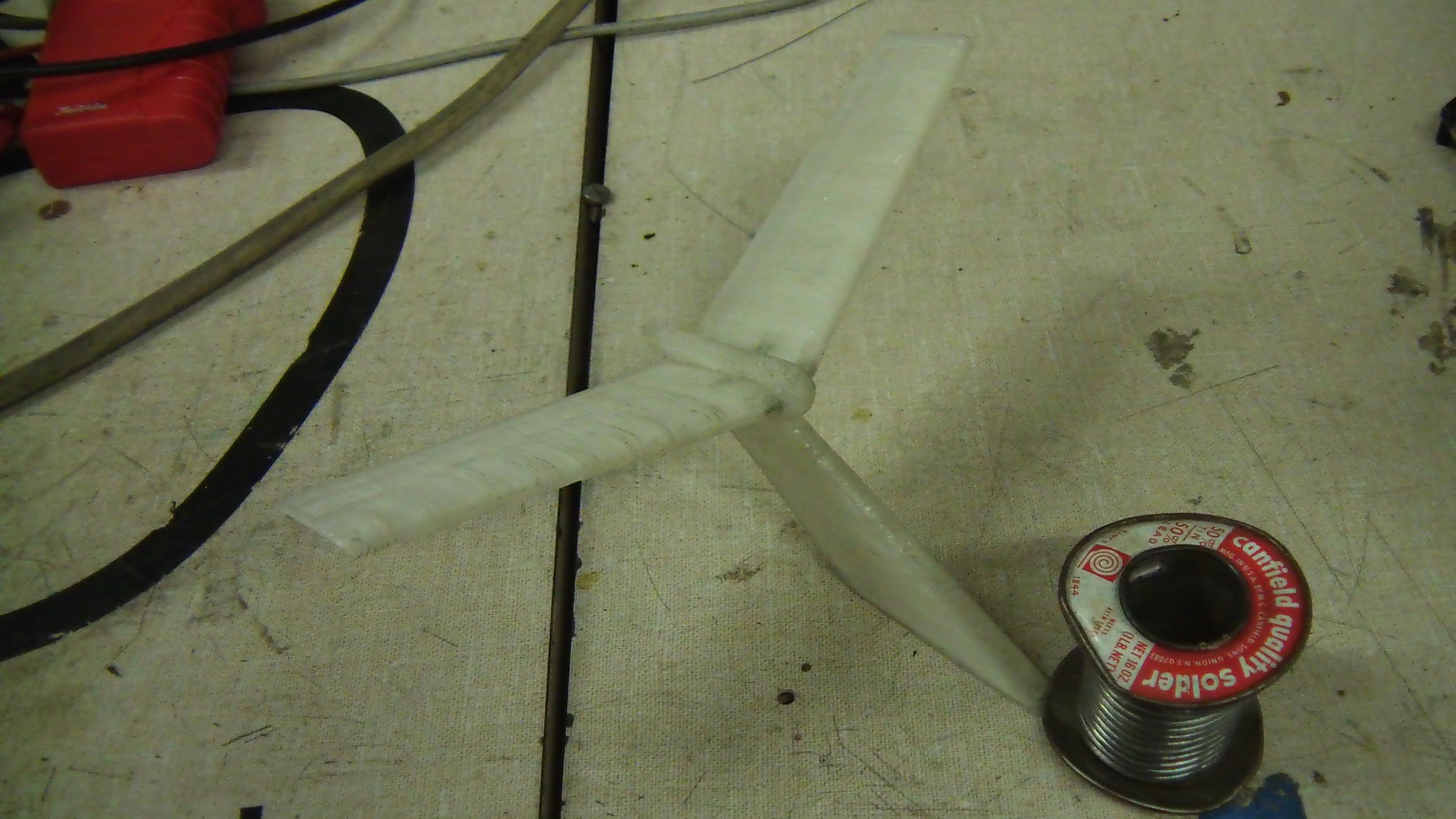
Continuing the assembly of the whole thing. The ass-end of the craft was printed horizontally because some of the sections were too small to print vertically (at least not without massively slowing down or waiting for the last layer to cool). I continued using the cut aluminum rivets method to align the parts.

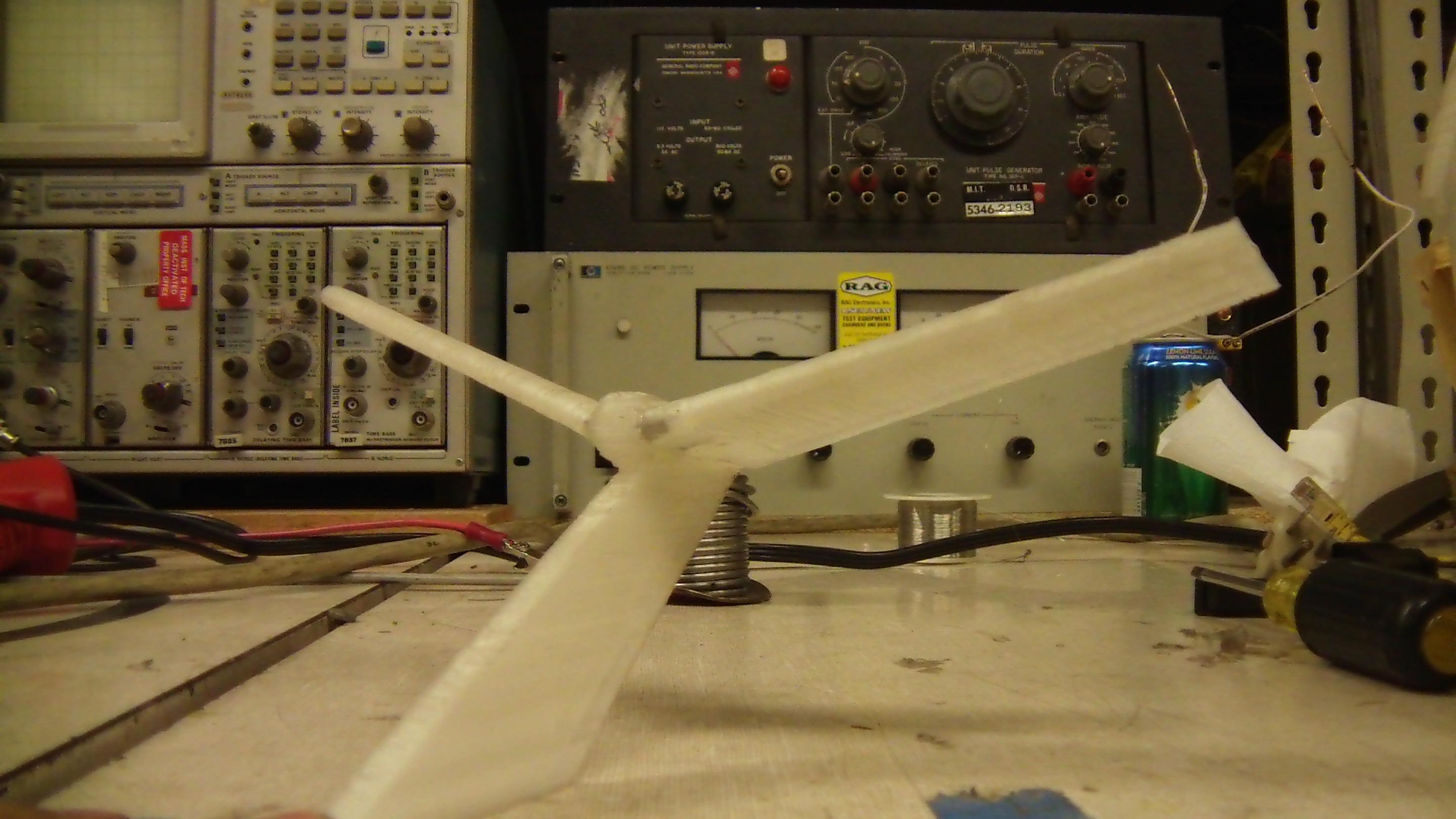
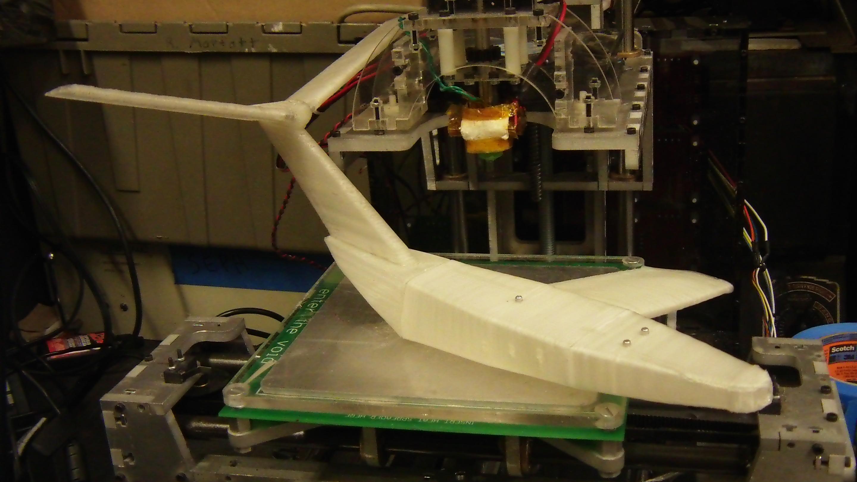
And here it is. I even included the bubble!

So how well does it fly? The answer is really not at all. As mentioned before, the tail is so heavy for one reason or another that it dominates the entire thing – the center of gravity is something like 80% of the way from the front of the wings (in airplane words, I guess that’s “80% chord”?) so the only thing it does when given a flick from ground level is stall out and then faceplant on the ground.

I taped little machine nuts to the front as a “counterweight”, but then it just faceplanted, being too heavy to do anything at all.  So for now, μ-Chuckranoplan 0001 will just be a display model. I’m not going to bother fitting it out with electronics.

How to fix this issue? Well, I could either build a model the way you’re supposed to build small aircraft models, which is with stiff foam, balsa wood, and plastic film, or make a better printable design. The real way is hard, 3d printing is easy.

I’ll probably redesign this thing to more closely follow the actual German delta wing designs, which, as this video demonstrates work excellently if they don’t weigh like 8 pounds.

micro-Chuckranoplan

Yeah, so I actually went and printed off some of the parts I modeled up for this thing. I guess that means I’m committed to finishing it, even if it’s just a small scale model. The project has been temporarily designated μ-Chuckranoplan. All the image links say “fb” because I codenamed the design file “failboat”, which is probably what it’ll end up being anyway.

Here’s MaB taking a shot at the tail fin. The whole thing is essentially one continuous 45 degree overhang, so I enabled the cooling fan to prevent sagging (It’s barely visible behind the extruder above). I was also concerned about the narrow contact patch with the build platform causing the build to detach midway, so I angled it at 45 degrees to encourage symmetrical movement of the axes. It turned out quite well, so the rest of the airfoil surfaces will also be done this way.

Blame the bad contrast on camcorders being very fail still cameras. Here’s the completed vertical tail with the “bubble” modeled all in one piece. There’s a small amount of sag at the top of the bubble, but overall it’s dimensionally accurate.

Next, I printed the two horizontal stabilizers . The whole assembly was smoothed over with some sandpaper before assembly. I just used some thin CA glue for the joints, since they did fit together quite well. Small chunks of aluminum rivets were cut and inserted into the 1/8″ diameter alignment holes to make sure the fins were at the right orientation.

Since the CA is intended just to align the wings, I’ll probably go over the joints with filled epoxy for added strength. The whole assembly is actually quite stiff.

And a better view of the area after the CA cured. I think I got the tail dihedral symmetric to within 1 degree….which, you know what, I don’t care any more beyond that.

Again, the sharp corners and unfilleted joints will probably be paved over with microsphere-filled epoxy.

More to come! I’ve actually revised the design slightly such that the fuselage is printable all in the same orientation for height consistency. One issue I’ve run into related to that is the lack of surrounding temperature control for the print. Attempts to print the main wing are resulting in prints that vary in Z height by 2 or 3 mm, but given that the wingspan is the Z height here, the wings are unbalanced. I strongly suspect this is due to variations in temperature and heat dissipation causing varying amounts of shrinkage in the plastic as the print grows.

The “deck” is now completely flat – previously, the nose portion was tapered downwards. Thus, I can print the three pieces “top side down”. I’ve turned the canopy bubble into its own part. The idea is to print this part as a shell so it can cover whatever mess I make underneath when I core out the body sections to insert batteries and electronics into. The three holes in the canopy align with mating holes in the body sections so I can use the same chopped rivet hack to keep the canopy on.

While I still don’t have the mini ducted fans to model, I think at this point their pylons will sprout from the back part of the canopy bubble – the white part.