In a previous episode of the quadrotor show, I mentioned modifying a single four-channel Hobbyking battery charger (this one) into four isolated single-channel chargers. Well, that operation has been done… so at least now I can charge the quadrotor in one shot. The process involves cutting some traces, a small amount of surface-smount desoldering, and getting four isolated power supplies for the resultant charger channels.
So this is what the inside of the thing looks like. It’s mostly three copy and paste operations, with a few differences to accommodate mounting holes and the fan connection. The main power bus is on the left side – positive on top, negative on the bottom.
The power semiconductors are all on the underside, heatsunk to the aluminum case with silicone pads. The board standoffs keep the switches pressed against the chassis.
These common power traces are the ones to cut. I used a Dremel with a cutting wheel to separate the trace into four sections between the inductors. The fans receive power from the very end of the power trace, so it is now associated with one channel (it will still turn on according to temperature, but pulls from the power supply for that channel).
After this, it’s time to get some power supplies.
I bought these cheap switching power adapters (supposed to be used for LCD monitors) from Ebay for something like $10 each. They’re about as shady as you can possibly get a power supply, I suppose. In fact, they were so cheap that I cracked one open to see if it was really isolated or not. I see an optocoupler and isolation transformer, so I hope that means yes.
The rating is 12v and 5 amps, which is about 10 more watts than the HK Quattro should be charging at (50 watts) so it was a good fit.
Each channel needs to be connected to a power supply. I just used the long wire the PSUs came with to complete this operation. Positive on top, negative on the bottom.
This is where I decided to get Extra Fancy and made a supplementary case to hold the whole thing. It was designed in around 3 hours and then cut out of clear acrylic plastic on a laser cutter. This step is of course not necessary, but it organizes the wiring alot. I dug an IEC power jack out of a pile of old power supplies and made a 4-way split cable with the line cords that the PSUs came with. No, it’s not grounded.
It’s also really hard to take pictures of clear acrylic.
The charger mounts on top of the power supply case using its existing four rubber leg things. After making sure it powered on, I reassembled the case and put the whole thing together.
Unfortunately, the first test proved to be inconclusive. While the channels were DC isolated, clearly there was still some kind of coupling going on – whenever one channel started charging, the rest of the channels would freak out and some times reset. If I started another channel charging while one was already running, all of them would freak out and terminate. The LCDs would also some times all blank if one battery was plugged in.
Clearly I missed something, so I took the charger apart again for a close flashlight inspection.
Here’s the culprit. I noticed a capacitor connected between each channel and the frame at each mounting hole. This is most likely a noise decoupling capacitor, but together they connect all the channels to chassis ground.
This is no problem if all the channels operate at pure DC offsets since capacitors are DC blocking. However, my guess is that the AC component of the switching power supply outputs is being transmitted across the capacitors on each channel, which is wreaking noisy havoc everywhere.
These caps had to go. There is one per mounting hole – just follow the lead emanating from the copper ring and remove the first capacitor you run into. And only that one, as far as I can tell. This can be done with a big soldering iron and a solder blob, or small iron and rapid back-and-forth heating of the two pads of the capacitor. Or you can dremel it off or something.
The behavior after this was much better. For some reason, the bottom channel LCD still has a contrast issue when any others are plugged in and running. However, it does not seem to affect the way it operates. I tried testing the isolation by trying random combinations of chargers and battery halves, and am proud to say that they all do work together.
The maximum charge rate for the Quattro on 5S lithium polymer batteries seems to be about 2.8 amps maximum. This works out to 60 watts or so, not accounting for inefficiencies (it does get quite hot for a 60 watt max charger – much much hotter than my 1010B+ ever gets, period). The shitty monitor power supplies also have thermal issues when charging at full capacity, so I think they’re either overrated or just that horrible. They only let the charger go full rate if there’s a fan pointed at them.
With these thermal issues in mind, I might append or redesign the base to house a small PC case fan. But in the mean time, it works!
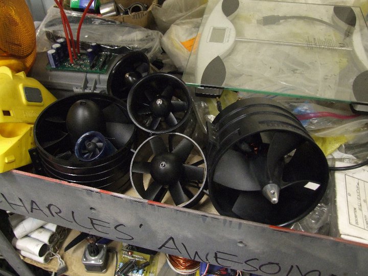
I already am publicly known to have an unhealthy obsession with Inexpensive Chinese Brushless Motors (ICBMs). But did you know that I’ve also recently grown an addiction for Inexpensive Chinese Ducted Fans? There’s no smart acronym for “ICDF”….except for maybe the Iraqi Coastal Defense Force or something.
Hey Charles, do you have enough of these things yet?
For one reason or another, over the past month or two, I’ve just been buying random ducted fans from Hobbyking (where else?). At first it was out of a desire to find a good propulsion source for Chuckranoplan 0004, which I promise is still under way. But then with the advent of Fanscooter and its derivatives, I’ve been thinking about ways to use these cheap EDFs effectively…. or just in large quantities, to get higher thrust values for any propulsive task I can think of.
background
Now, real EDF systems from European and American boutiques are known to be great performers and are well-built – generally made of metal alloys or laid up from carbon fiber and dynamically balanced. These are the things that tear ass at upwards of 50 to 60,000 RPM in model fighter jets that go 200 miles an hour or more.
The problem is that they are EXPENSIVE. Like, dear Robot Jesus are they expensive. The TF8000 is generally my calibration point for how much I can’t afford a quality large EDF setup – the fan itself, without a motor, is $600. The motor is usually an exotic German make (like Lehner or Hacker) that costs $700 to $1000 by itself. Throw in the extra bigass controller you need to run that motor and you’re looking at nearly $2,000 for a single thruster setup. Granted it is like 30 pounds of thrust, but still – how do these guys even?
I mean, besides massive funding.
That’s why I have decided to explore the parallel design space loci a little, since it doesn’t cost too much for me to do so. Hobbyking currently has two large EDFs, both in the 5 inch (120mm) range, and I got them both.
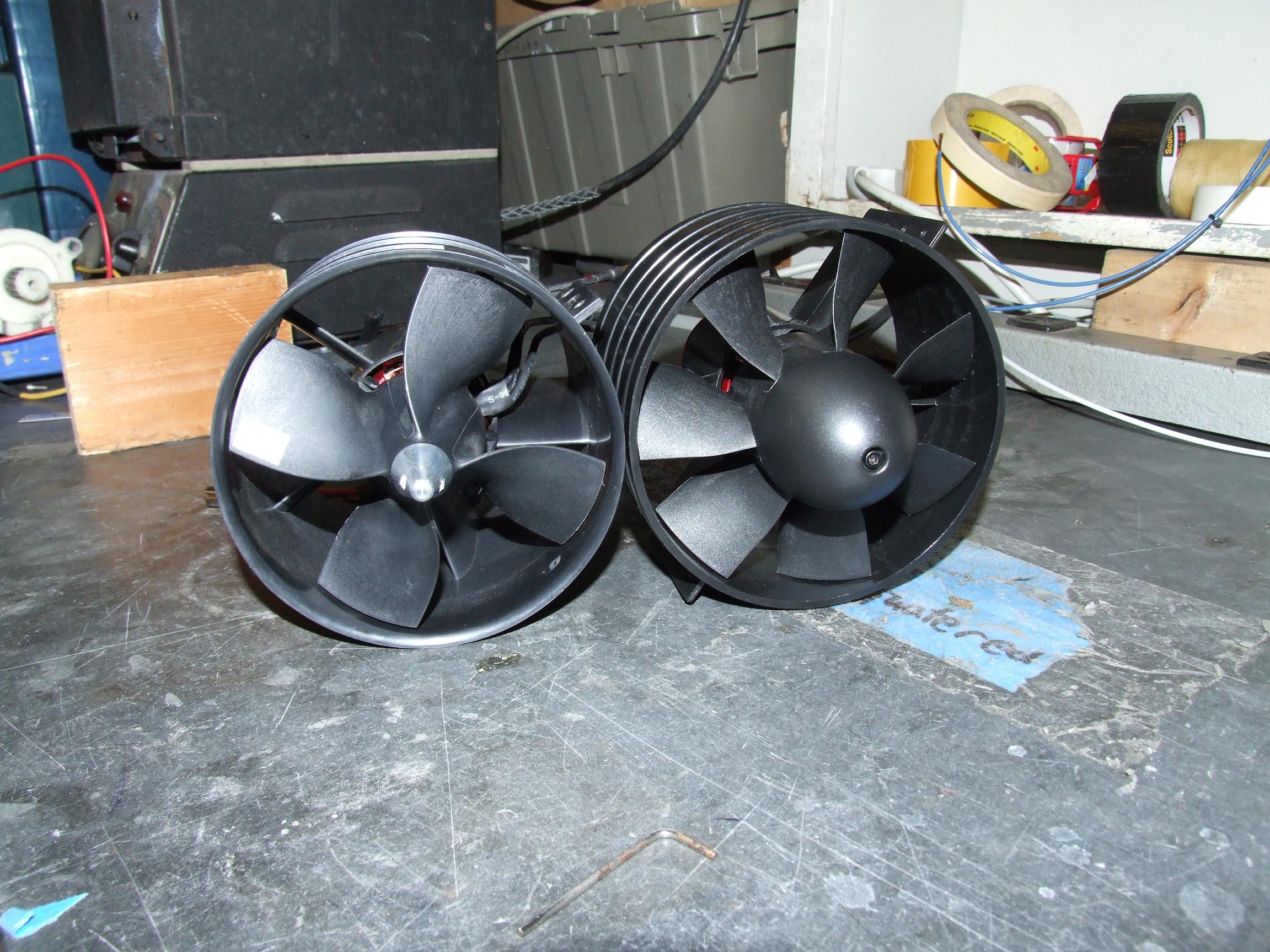
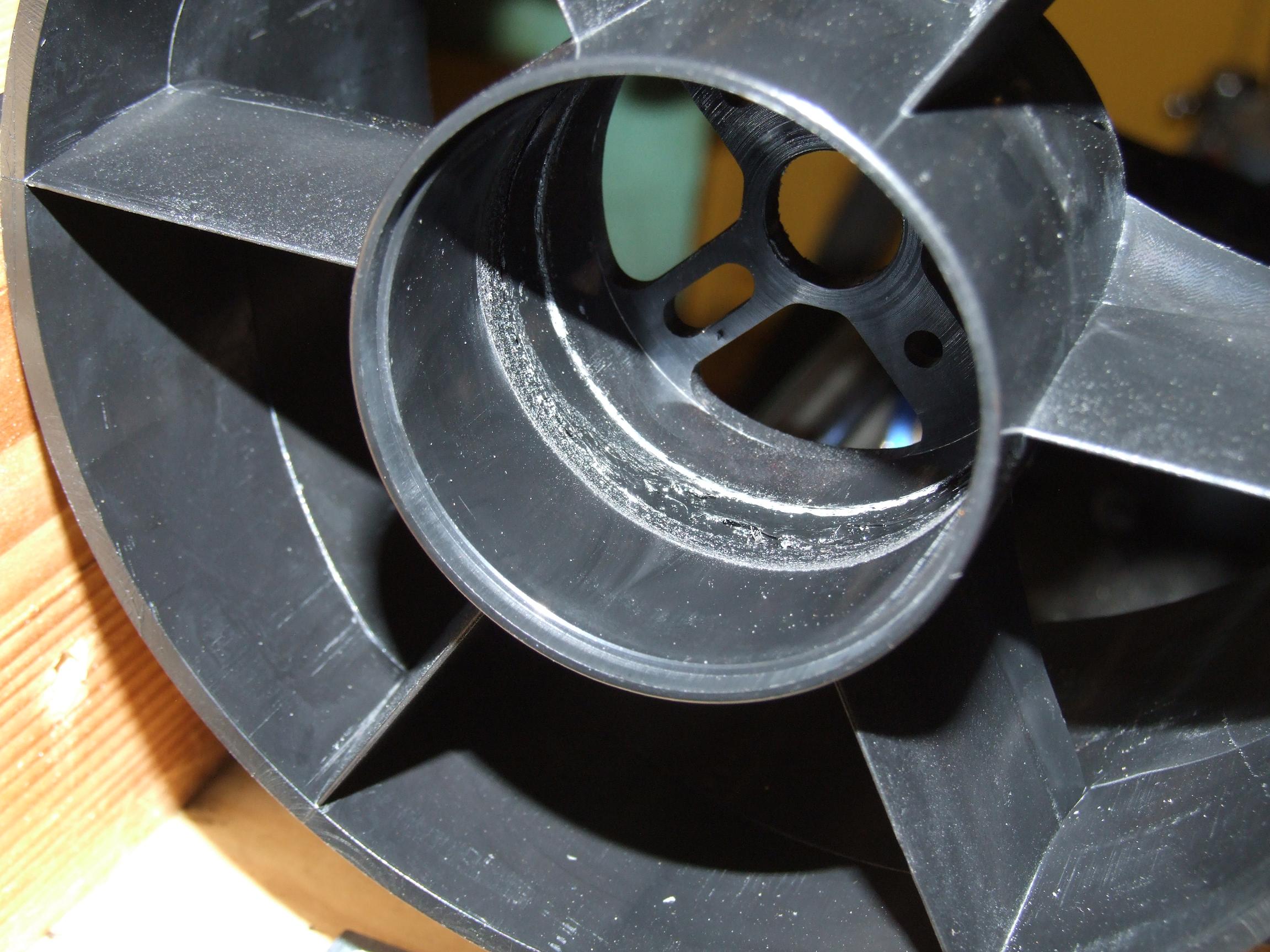
HK #OR003-00113-7B Haoye 125mm rotor, 7 blade. This one has been around longer, but I only got it recently on a whim. It has a set screw type propshaft for 6mm motor shafts, and a removable nosecone. The construction seems to be pretty standard “cheap EDF” – unreinforced plastic (ABS, judging by the smell… read on to find out), but the rotor looks to be glass filled nylon. The price is $30, and the maximum motor diameter is about 50mm or so.
HK #102F “ChangeSun” 120mm rotor, 4 blade. For 40 bucks, I threw one in on a parts order for Chuckranoplan. I like the construction of this one much more. The propshaft is a collet-type one, not a set screw, and the shiny aluminum nosecone is also a nut. The rotor and casing are both made of fiber-reinforced nylon and both are very stiff…which fiber is, of course, dubious – carbon fiber is claimed, but why do I not believe that? The maximum motor diameter is 52mm.
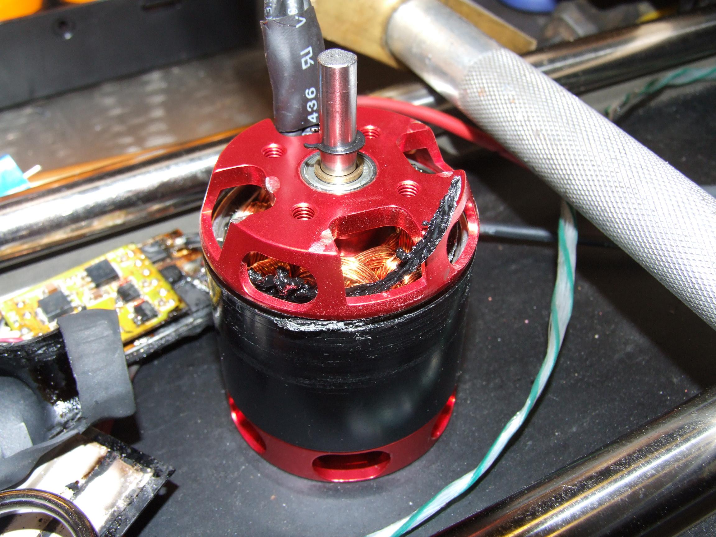
Finding motors to drive these fans was difficult. HK doesn’t have purpose-build EDF motors larger than 36mm (the type which has a tailcone and longer shaft). I also was not too please with the reviews on their large inrunners (up to 45mm diameter), and I hate inrunners anyway. The only thing left that was in stock were 600-class helicopter motors. I ended up getting a T600-880 and then a T600-1100 – two different winding variants of the same motor so I could test different battery voltages. There were some motors with potentially higher power, but they were not in stock and if I backordered them, I would probably get them some time in late September of next year.
Just to give an idea of how stupidly big this thing is… here it is next to a commonly scale item. The outer casing on this is about 130mm.
A few unrecorded test spins of the fans revealed their very, very Chinese nature – the rotors themselves were severely off-balance. Using the über-cool magnetic levitation feature, I attached little chunks of rubber magnet stock I found at MITERS to the interior of the rotor using CA glue until I was satisfied. That step was easy enough. At least the Haoye unit had a straight propshaft (set screw notwithstanding): the ChangeSun’s propshafts were completely and utterly useless. They fit the motor shaft well, but they were drilled off-center and wobbly, and the aluminum alloy was also rather soft.
Seriously, what a corner to cut. The rotor itself and casing are both very nice injection-molded parts, but the one critical component to connect them is garbage. Because of this inherent Chinese-ness, I can’t recommend them to anyone who isn’t willing to put some work into polishing them up.
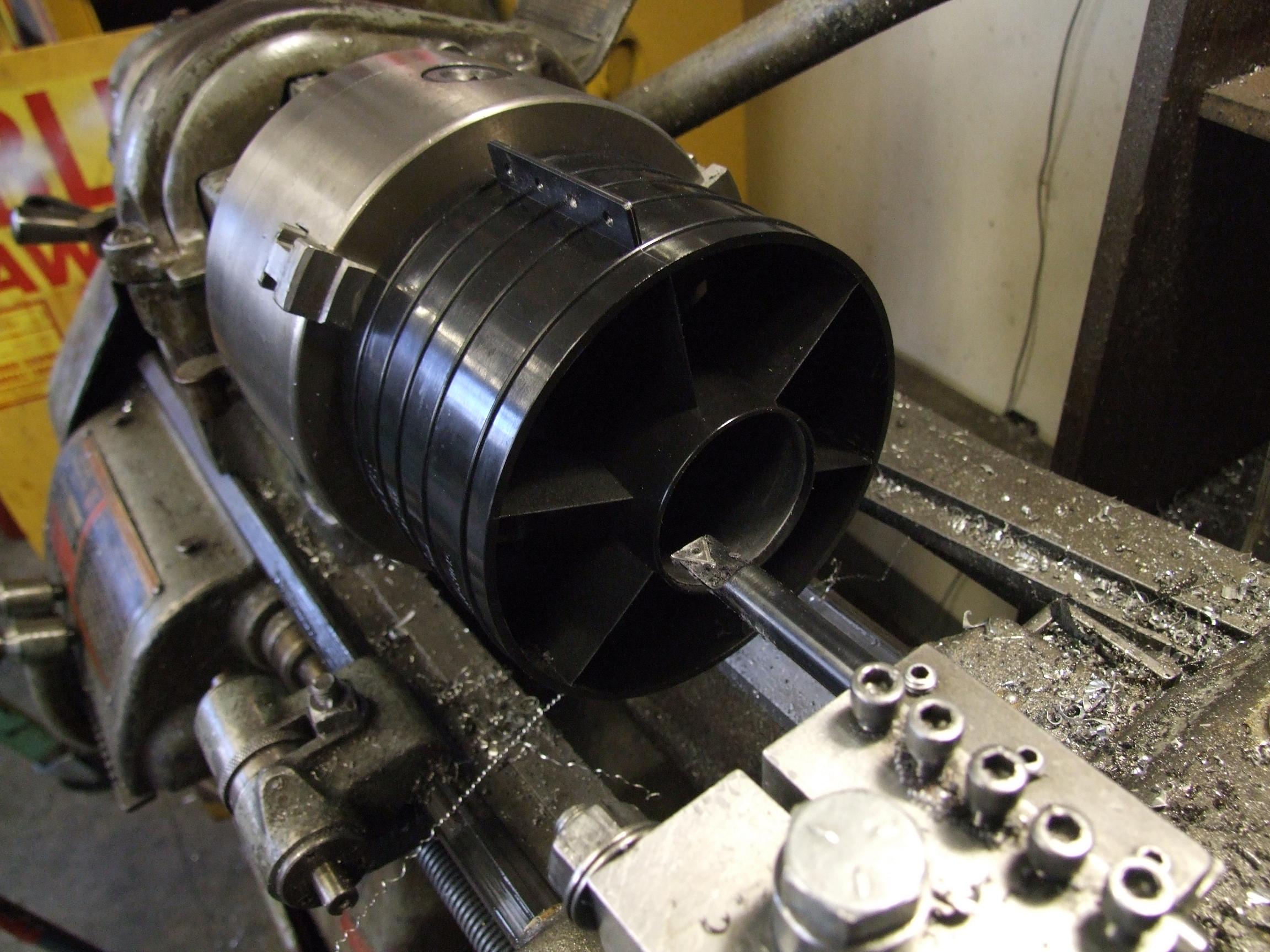
For the ChangeSun 120mm fan, “polishing up” meant putting the 5mm adapter on a lathe and carefully reaming the bore to 6mm. In order to eliminate one major source of uncertainty in this, I elected to perform the operation on a nicer campus student shop machine.
Four blades versus seven… which one will win?
As usual, I’m interested more in the static and quasi-static (read: slowly moving forward) thrust of these fans. I’m not likely to build something that travels very fast or anywhere near the “prop speed” for these things, so my testing would focus on static thrust characteristics.
The T600 motors seem to be a good fit for both, but is a little tight on the Haoye 125mm (This would later prove to be a little tighter than I imagined). On the Haoye, the vent holes of the motor can stick out just enough to make it look like it was meant to be there…as well as providing a better airflow path.
On the contrary, the motor is pretty much flush with the backside of the ChangeSun 120mm fan. The vent holes are therefore much less effective here. This may have implications for continuous high-power operation of the whole assembly. A longer (read: more powerful) motor would be better for it.
In the picture, I was executing the auto-“Hey, hold this while I plug it in” test on the Haoye fan. I didn’t hold on for too long…
procedure
To measure the static characteristics (thrust, RPMs, power consumption), I set up the Fankart test rail. The EDFs are screwed to some cut-off 2×4 sections, which are in turn clamped to the linear ball bearing platform. I rigged up an electronic pull scale behind it, and located the controller (and Turnigy power meter) near that. You can already see the dot of retroreflective tape I attached to the rotor so it can be measured using laser tachometry.
I make “laser tachometry” sound ultra-sophisticated, but it’s this one. You should get one since it’s useful, but it needs reflective markers – a sharpie mark won’t do.
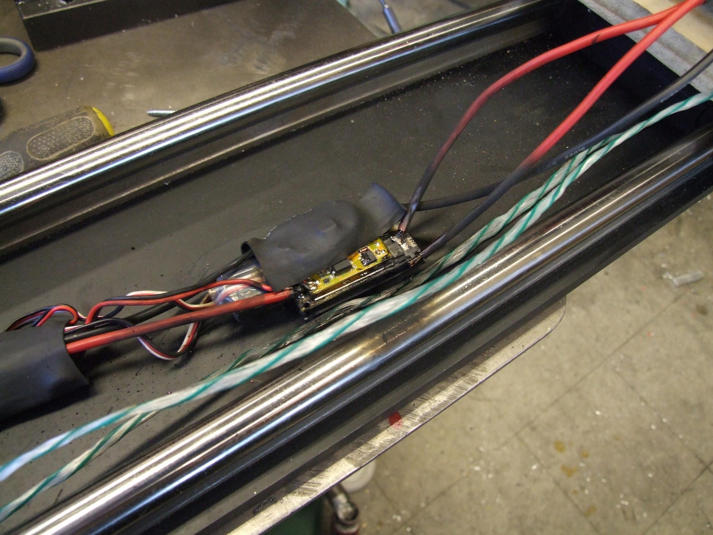
Next up was the Haoye fan with the T600-1100 motor already loaded. At the very start, I noticed the current draw was much higher than I would have expected. But the ESC is (allegedly) 80 amps, so I kept going anyway.
At somewhere near top speed, the fan suddenly locked up…and then this happened.
The destruction was instant.
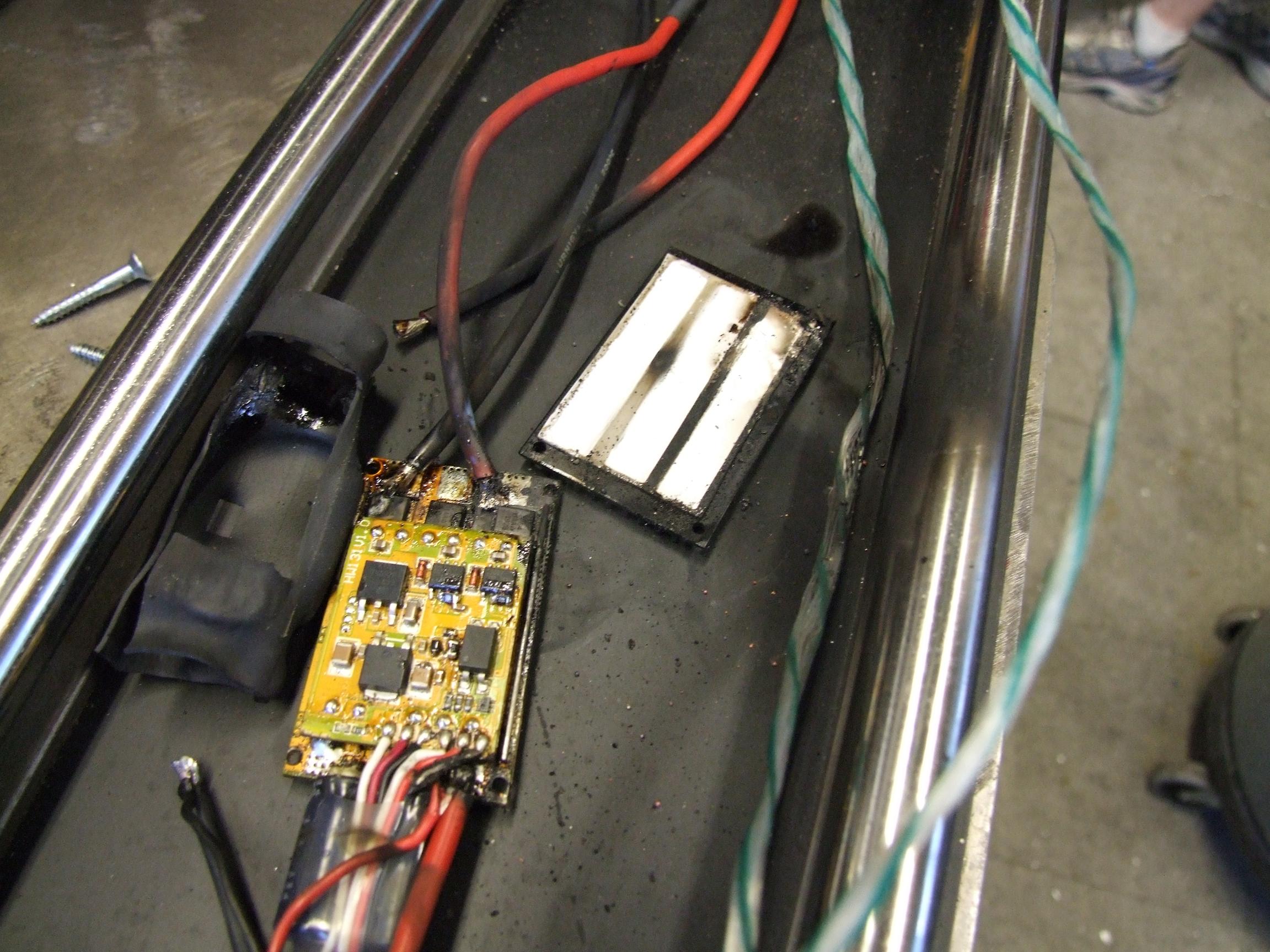
Model airplane controllers really amaze me in how close the components are pushed to their absolute maximum ratings. They also have absolutely no protection whatsoever – at least, in this case, the protection wasn’t fast enough to respond to a sudden locked rotor at full throttle. The thing lit up and actually started shooting jets of fire.
Yeah, it’s pretty gone. The shorting current was enough to blow off several wires completely and heat up my double 14-gauge battery jumper. So when this happens to your plane in midair, does the whole thing just light on fire or something?
I literally had to hammer out the motor from the casing. Something went terribly wrong…
Yes, that is a ring of melted ABS plastic hanging out of the motor. I know it’s ABS because it smells like all three cancer-causing constituents of ABS plastic, and is the smell that Make-A-Bot constantly creates when it’s in operation.
It looks like a severe case of… well, severe case interference from the distal end of the motor can to the walls of the housing. What this tells me is that the T600 is just a bit too large in diameter to really fit the housing, and the vibrations induced from operation are enough to make the can scrape the inside. At high speeds, this translates into quick rapid heating that melts the housing and turns the plastic goopy.
I assume at some point enough plastic goop is hanging onto the motor to drag it to a stop. No data was recorded on this run because I was too entertained by watching controllers explode.
While the long-term solution for this problem is to find a different motor, the short term one is to just bore the housing out. I took everything out an extra millimeter so the motor had plenty of clearance.
After that, I remounted everything and, using a different controller, put the test rig back together.
results and discussion
The test on 10S LiFePO4 cells with the T600-880 motor yielded:
19100 RPM
2.9kgf static thrust
95.5A peak
30.01v minimum.
I elected to not even try the 1100kV motor in the Haoye fan after this, since it would probably just try to pull a thousand amps without getting much work done. Judging by the very low RPM figure, the readings are reasonable. It’s clear to me from looking at the fan blade geometry that the Haoye is designed for a very high vehicle speed. The blades are very heavily pitched (actually perpendicular for the most part) and not very swept or twisted at the tips (not much washout, a plane word I learned). From the findings on Fankart, this would make for worse static thrust per power consumption, and the results reflect that here.
Further tests with the ChangeSun fan on 12S LiFePO4 (38.4 volts) found that it’s very well paired with the T600 motors at that voltage. I got the following data points:
31.1Vmin, 53A continuous, 2.8kgf static, 24800 RPM with T600-880
30.0Vmin, 86A continuous, 3.8kgf static, 28500 RPM with T600-1100
36.7Vmin, 75A continuous, 4.1kgf static, 28540 RPM with T600-880 on 12S LiFePO4
I also decided to not test the T600-1100 on 12S since it was clear the continous current was going to be over 100 amps, and the motor will definitely not take that much. I think even 75 amps max is pushing it for the T600-880 motor.
I think to prevent future friction stir welding situations, the motor should be a large inrunner, preferably with an aerodynamic tailcone. The problem is that HK doesn’t carry huge inrunners yet, and real inrunners (from say, Neumotor, Lehner, Hacker, etc…) would be kind of lame to pair with a cheap fan. So if you know any Chinese inrunners in the 50mm size class and of more than 2+kw continous power, let me know.
conclusion
Wait…what the fuck is this, a 2.671 paper?
Anyways, the conclusion here is that for a little over $150, you can get a solid 4 kilograms of thrust from the HK102F “Changesun” fan paired with a T600-880 motor, running on a 100A Turnigy HV controller. 12S LiFe cells is very much equivalent to 10S traditional ltihium polymer, and if you pair it with a DEAR GOD WHY DOES THIS EXIST 10S pack like this 5.0Ah pack from HK, then for less than the cost of like, one fan blade on the TF8000, you can have a full 4kg class power system for around $300*. Most likely, that battery can feed two T600-880 powered fans at the same time – 150 amps continous (75 amps each) is only 30C, which is within the rating of the battery, and have a system capable of 8+ kg thrust. Put two of those system side-by-side, and you’re looking at something which can lift Überclocker straight up in the air.
Just saying.
Oh yeah, if you want to hear what a (balanced) one of these sound in action:
*You better have a machine shop to clean up those propshafts though. I have not tried running the CS 120mm fan with the stock propshafts. They scared me too much even on low speed.