Alright, now that I’m settled in 900 miles from civilization out on the west side of the MIT campus (seriously, how do people live out here?), it’s time to comprehensively update everything. Dragon*Con is now in approximately 2 and a half weeks. So, the flying objects have been temporarily suspended in favor of two more immediate goals which I mentioned briefly before.
1. Getting the robots running again, since I ain’t going to no Dragon*Con Robot Battles without no robots.
2. Repairing some of the random vehicles, since they (along with the robots) will be exhibited at the Atlanta Mini Maker Faire hosted at Georgia Tech in a few weeks.
I’m just going to start laundry-listing everything. First, the most interesting of the upcoming builds, a rework of Pop Quiz 2.
This was the state of the robot as of two weeks ago:

Yeah. It’s kind of trashed.
PQ2 hasn’t seen any action since Robot Battles 2008, and it lasted about 20 seconds in the arena then. So how on earth did it get so destroyed? Mostly because I kept pulling parts from it and then stuffing them back without closing the bot up. I’m sure it’s also been dropped a few times, and I might have also landed Clocker on it a few times too. Pretty sad overall; while the frame is perfectly workable, I don’t like the way the frankenmotors worked out (and one of them has been missing from the start). The offset wheel axles mean that I can’t just directly swap in a micro gearmotor or similar without making the wheels much larger. Oh, and all 4 lithium cells are dead. It’s a little easier to just start over.
What few people know is that PQ2 has been up for revision several times before, each time I ended up pursuing something else instead. I designed a new version of the robot to be built for the 2009 Robot Battles, but didn’t get around to finishing it.

This version was to have a waterjet-cut aluminum frame and replace the frankenmotors with Sanyo micro gearmotors. I even got around to cutting the frame:
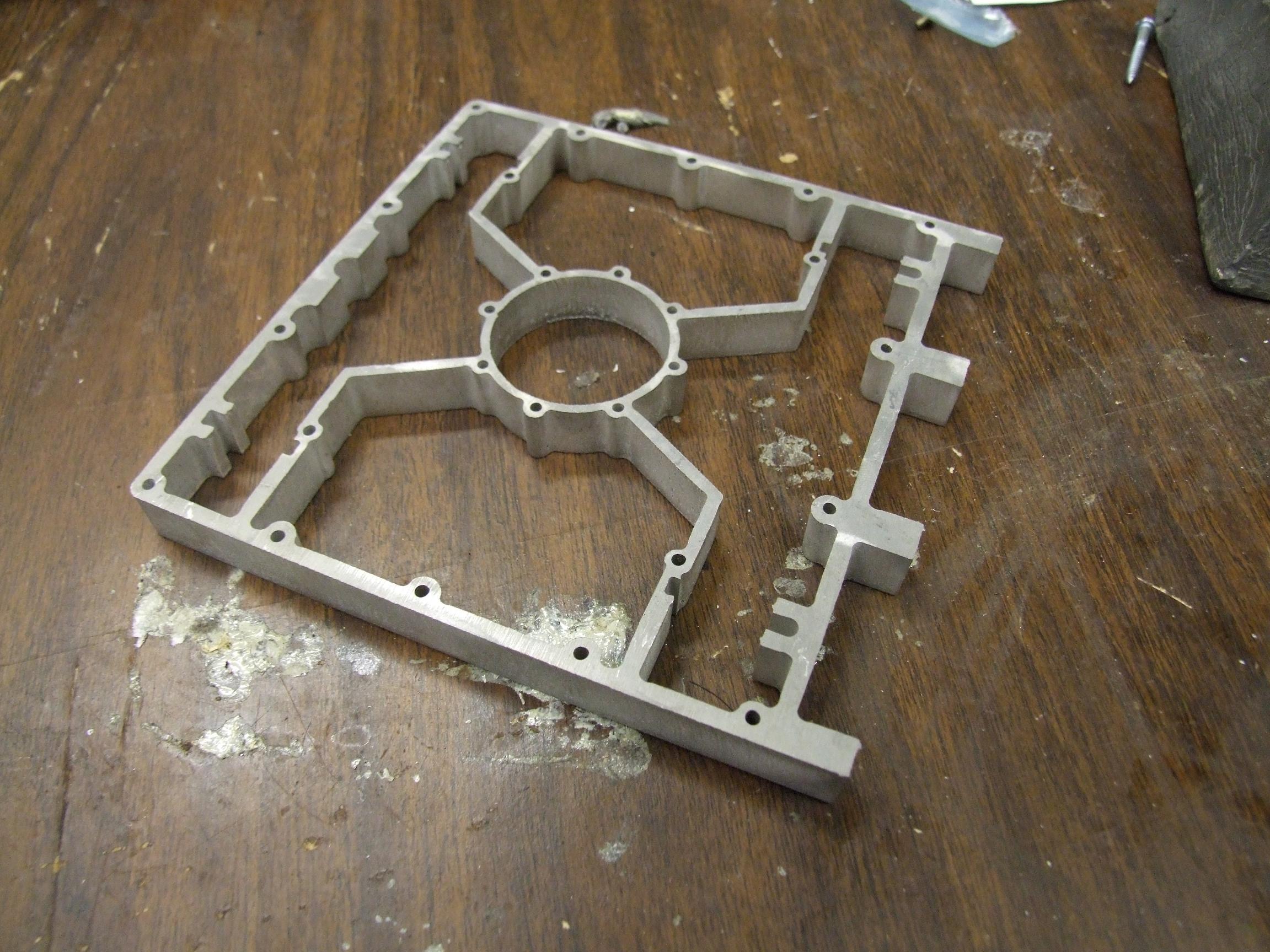
It was made out of 1/2″ aluminum with the intention of machining it down to 10mm (.39″). Now that I look at it again, I wasn’t sure how this was supposed to be done.
Actually, no – I do know. I was going to actually make a fixturing block for it and then meticulously machine it in sections, taking out a subset of the fixturing screws as needed. And then I was going to turn the head of the Bridgeport mill 45 degrees to machine and drill the holes in the front. Then I was going to flip it over and carefully use a boring head to make the inset in the center for the motor mount.
I remember being hardcore like that. But now, in 2011, there’s a better option.

YES! It’s another excuse for me to abuse Make-a-Bot. For a while, I’ve thought that ABS plastic should be durable enough to withstand 1lb and 3lb arena combat. So this is a thought experiment (turned physical) that will use a fully 3DP frame, with carbon fiber top and bottom plates as before. The drive motors are still Sanyo micro gearmotors, and the wheels will be machined plastic things with silicone tubber tubing tread. \
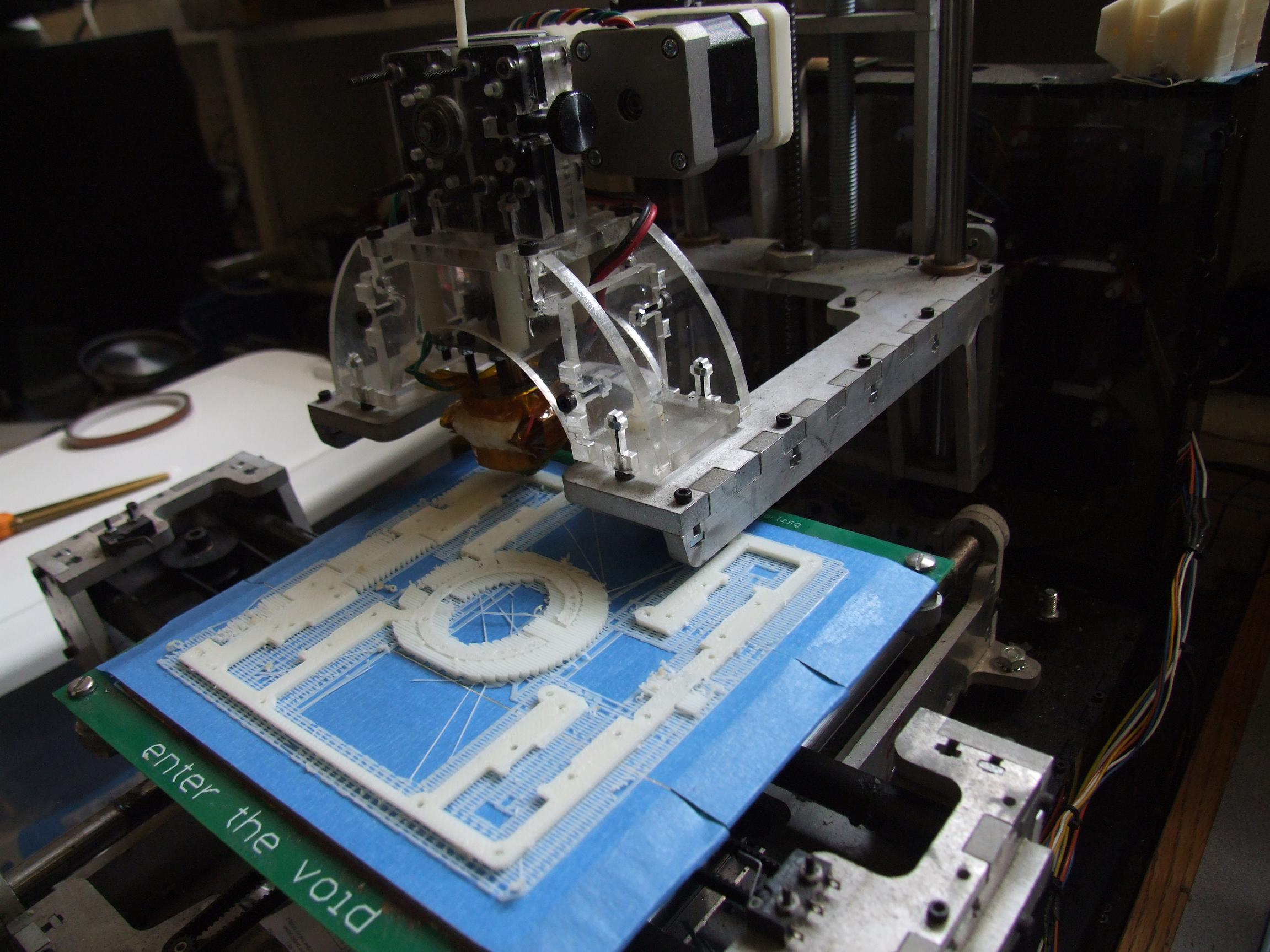
Here’s the entire frame being fired off at once. 5 x 5 inches is still with MaB’s build envelope. However, given the geometry of the part, I didn’t expect this to turn out well – MaB has no climate control, so large parts still tend to warp. Especially a 5 inch long solid bar.
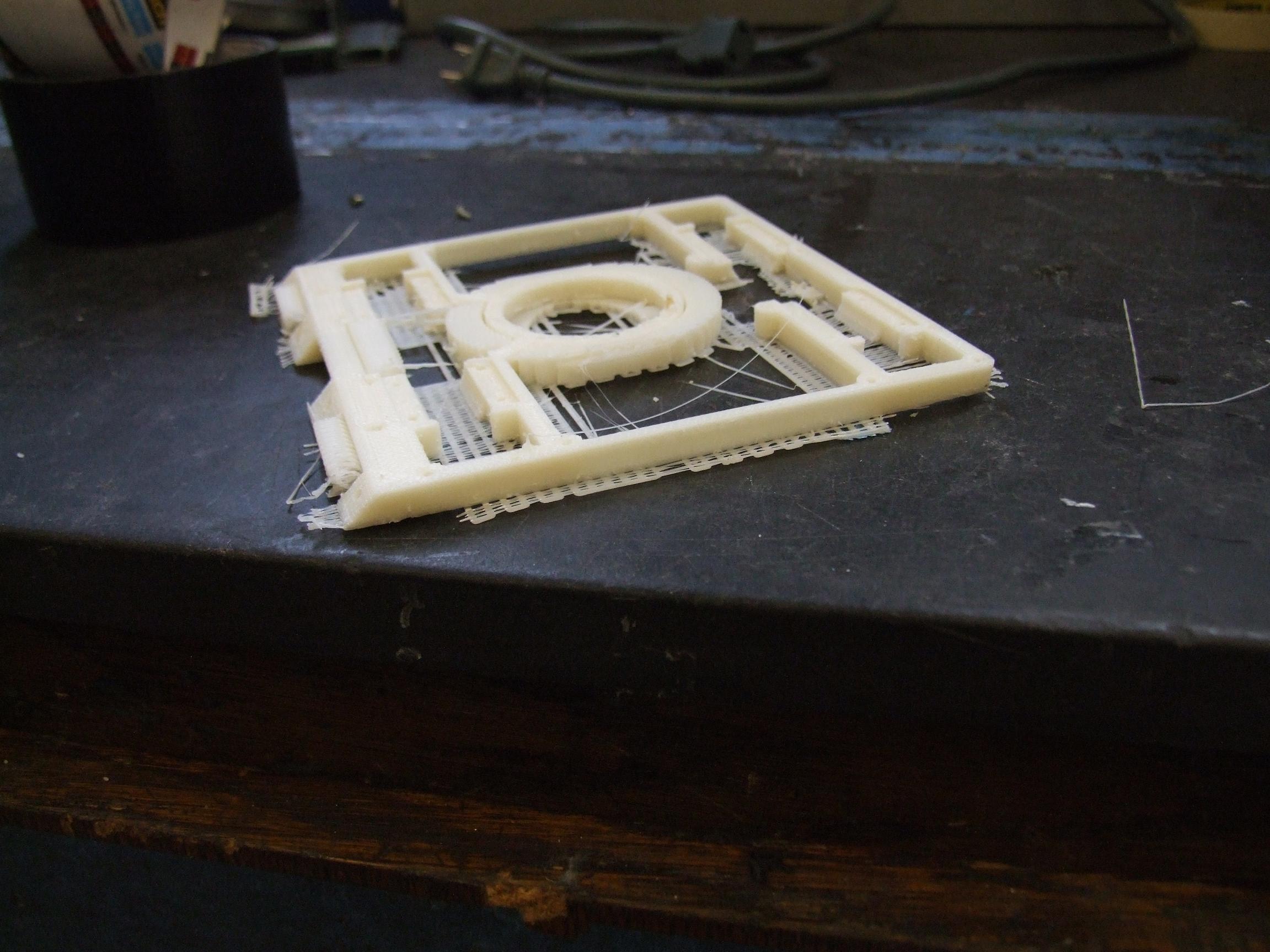
I stopped the build after noticing that two corners were coming up. Because the robot is so short, a millimeter of curl would spoil the ground clearance and wheel contact.
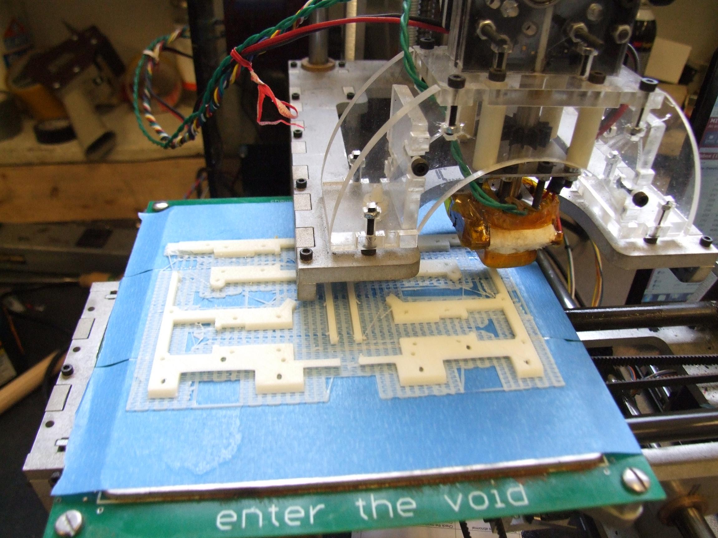
The solution was to just split the frame into 4 quadrants, such that the longest continuous span was 2.5″. This relieves much of the stress from the parts not being in thermal equilibrium. In the best case scenario, I’d have MaB in a closed heated cabinet at about 120 degrees Celsius or more. Then I could also make cookies in it!
With all four frame quadrants made, I’m just waiting on carbon fiber sheets and spring steel to arrive.
I might also rewind the weapon motor to run on 7.4 volts instead of 14.8. Originally, I did it to avoid running high current in the robot, instead choosing to run a higher voltage for the same power. After building vehicles, on something this small, the difference is trivial. Using the lower voltage would mean the Sanyo motors will be much happier (they’re native 5 volts!) and I’ll have a chance to try out these VEX controller units, which are the cheapest small robot control option I’ve seen, ever.
überclocker
Suffering another loss last year due to my lack of care for detail and “baaaah, it will be fine”, ‘clocker is actually functional otherwise. The left side gearbox slipped my inadequate press fit on its output shaft early in a match, leaving the bot mostly handicapped through the tournament.

I took the bot apart to extract the gearbox, but also to clean everything up and tighten screws. It was missing a receiver (which after some digging, turns out I borrowed to use on the cute little prototype Coasterbot), and one of the Victor 883s was not responding to signal. I found out why it wasn’t receiving signal very quickly after extracting it and pulling the servo cable out: the entire internal header inside the Victor came out with it.

Oops. Solution: Make a short servo cable pigtail that passes through the cable shroud so I can still connect to it. After this, it worked fine.
The gearbox fix was quick and simple: press out the spun output shaft from the planetary carrier, throw it on a lathe, and carefully knurl it. The knurling increases the outer diameter of the shaft slightly by introducing ridges and valleys. Then shove it back in with a tanker-load of 609 Loctite, some of the stiffest retaining compound there is. Knurling also helps make threadlocker and retaining compound adhesion stronger due to the same reason – it seeps into the gaps and is therefore able to coat more surface area.
I have no pictures from the knurling process since it was done at another shop (MITERS not having a knurling attachment for the Old Mercedes)
Past putting the robot back together (and driving it into everything at full speed, repeatedly), Clocker will not have any modifications made. I might turn the clamp motor around so it has more travel available, however – right now, if I don’t pay attention to where the clamping arm is, it tends to wedge itself in the highest position and the motor is then unable to free itself.
Clocker and Pop Quiz are the only robots I intend on bringing this year – NK got banged up nicely last time, and I haven’t rebuilt it yet.
RazEr rEVolution
Ahh, RazEr. This thing has just been *working*, though I’ve only really brought it out for demo events because of its concrete-hard wheels. However, Maker Faire ATL is a demo, so it’s time to turn the power on and test it for functionality…
…
…wait, what do you mean I left it powered on?
Yup, RazEr’s battery is now completely flat after being left on for what must have been a month or more. I need to take it apart anyway – the way the pack is set up, it’s impossible to charge using my R/C multichargers. I split the pack into 2 strings of 6 A123 cells (but run in series for 12 cells), however I neglected to break out the middle connection so I can actually like… charge it as two packs. Or balance it, or do anything really. This should be a quick operation.
Segfault
Another one of my finished things that just works, Segfault has also been a demo piece for most of this year also. The breadboarded controller is becoming incrementally more flakey, however – probably because breadboard. Sudden direction changes or even slowing down/speeding up quickly tend to cause noise which appears as a jerk in the wheels. I can anticipate and compensate, but it’s enough for me to no longer let other people ride it. I have a desire to put the controller on an actual printed circuit board that’s fully integrated so there’s less messy wiring, but that is unlikely to happen in the next week.
However, it does need some minor mechanical attention. The steering column potentiometer is heavily biased rightwards from when I replaced it. The left side gearbox for some reason tends to slip its output shaft (What’s with me and half-assed gearboxes?) which, fortunately, is not a Charles-induced manufacturing fault this time. Segfault uses 2 Banebots P80 type gearboxes, and the last stage planetary carrier is connected to the output shaft with a double-D flatted bore, which seems to be prone to axial misalignment. Usually I can kick the left wheel back in and it reseats fine – not a critical mechanical problem, but still annoying.
land-bear-shark
You know I couldn’t leave this thing alone for long. Last time, I said I wouldn’t touch it until Winter. However, seeing as how it just rained, it’s now chilly outside, so I declare Winter.
As usual, I will preface a LBS post with a new motor controller. Another new motor controller.

What’s different this time? Well, besides it being the densest through-hole board I’ve designed to date (because why not), it uses the IR21834 gate drive chips. Watch that number there – it’s the independent input version of the 21844 I am fond of. This means the high and low sides are switched independently, but it still has built-in deadtime.
This frees me from the implicit braking of synchronous rectification if I’m too lazy to implement current control (which I am). I’m more accustomed to freely coasting vehicles, which the implicit syncrec of the 21844 does not let me do unless there is a current sensor and current control loop (such that the motor controller output voltage matches the motor’s back EMF)…but that’s more software.
With the 2183, I should be able to drive the high side switches only, while otherwise keeping the low side switch from turning on immediately afterwards. This would let a vehicle, say RazEr, coast freely. Regenerative braking can still occur if I command it.
A vehicle like LBS doesn’t coast at all due to the high friction of the tracks, but this controller will be a chance to test the 2183 before I put one in a more serious application like RazEr. It’s already been sent out to Retarded Circuits for fab and should be here later this week.
I’ll also need to perform battery and motor surgery as outlined previously, but this should be coming down with me too.
