BurnoutChibi’s Steering and Braking

In the past week, I’ve been managing to intersperse bits of BurnoutChibi work between hosting extra hours for the 2.00gokart students as they edge ever more towards completion. On Wednesday, the “Milestone 7” mechanical inspection occurred, where everyone had to demonstrate their rolling frames with steering and braking. The next steps for the students from here are focused entirely on assembling their electrical system. In fact, two teams have already blitzed their vehicles to completion, and more are surely to follow (parading them around during CPW is a huge motivator). I’m going to make a separate post about the progress of the class later – all I can say for right now is that this year’s competition is going to be awesome.

The first thing I had to do to build a new Chibikart is to disassemble the old Chibikart. Here’s the scene of the crime:

This work left me with a pile of redundant electricals – namely 4 more Jasontrollers and the massive A123 B456 battery. Needless to say, these will probably find their way into some other silly rideable thing.

The plan for BurnoutChibi’s electrical system is actually to use my left over 10S 5Ah lithium polymer packs, instead of making a custom pack or keeping the A123 pack. I decided to this mostly for the power and energy density of the lithium polymer packs (Chibikart 1 weighed 53 pounds because the big A123 bus battery module weighs almost 20!)  as well as the simple fact that said lipo packs have been sitting for almost 2 years, and I really don’t want to see them go to waste. The lipos themselves are from the erstwhile Deathcopter, so BurnoutChibi will surely be the health and well being hazard I envisioned it to be.

The first appendage to the old frame is the new style brake pedal. At this point, I haven’t even removed the old steering linkage yet, but I wanted to see if it would interfere with the new position of said linkage.

I started from the rear with fitting the Vex Ball-shitter transmissions onto the “goalpost” mounts. This whole ‘rebuild’ is essentially replacing Chibikart 1 frame plates with specially crafted DPRC ones. The only difference between this rear corner and DPRC’s is the goalposts!

I focused on getting the motors mounted and the rear end together. Here, I’ve mounted the NTM motors to my NTM-to-CIM converter plates. Eliminating units, the result of this evaluation is something which is basically like a CIM, but 4 times more power dense.

There’s only one problem. The NTM shafts need to have a 2mm keyway cut into them so I can easily used the keyed bore supplied with most FIRST OEM parts such as the Vex transmissions (The fact that I can say “FIRST OEM” is unsettling).

As it turned out, these shafts are casehardened. Wow, Hobbyking, you’re classy now – what this meant was I could not use my single HSS 2mm endmill to machine the slot. Instead, I went on eBay a few weeks ago and bought some 2mm solid carbide endmills. I recommend keeping a set of carbide cutters around for dealing with troublesome materials; the downside, of course, is that they are more brittle and need a stiffer machine setup.

I faced the slight issue of the endmill being too short and the Bridgeport spindle being too fat to reach the nether regions of the  motor. So I did what any self-professed machinist wouldn’t do, and chucked it up in a drill chuck. In my defense, I bought this integral-shank keyless chuck just to do dumb things like this.

I cut the keyway just a little short of actual dimensions because the NTM shafts were not long enough to use the included retaining ring with the gears. So I had to press the key in,and will need some creative gear pulling if I ever wanted to remove these gears.

And here they are mounted. I found the sheer number of hexagonal sockets on the gearcases a bit confusing at first, but now appreciate how versatile they can be.  Chain tension is adjustable using the slightly slotted mounting holes. I inserted locknuts (nylocks) into the opposite side hex sockets, so torque retention will be positive.

Notice how the seat mounts have been turned around. This was necessary because of how big the gearcases were. The seat mounting centers, and overall position, will remain unchanged.

Crawling up the side of the vehicle, I reached this build’s star attraction: The gear shifter. This came together amazingly well, and the feel of the ball detent plungers is extremely satisfying.

Heading up front, I popped out these new steering knuckles. In keeping with the tradition of doing the least possible work, these were specifically designed as drilling operations in a 1″ aluminum square barstock. The four flange holes will be where the drum brake mounts.

Continuing work on the front end, the drum brake mount has been attached and the new narrower steering…ears? are mounted. I’m not sure what to call them on Chibikart. They’re too short to be A-arms or wishbones.

Recall the new steering linkage arrangement – the crank arms are basically socket wrenches that fit over the hex head bolts. Motion is transmitted via giant set screw in the steering knuckle. To ensure positive engagement, I machined a deep flat into the hex head bolt shanks and picked flat-bottom set screws to maximize the contact area. To retain the crank arms, I center drilled a hole and threaded it for a retainment bolt. Otherwise, the crank arm is thinner than the bolt head and will be free to float about 1/16″ or so.

I moved on to chopping up the 90mm drum brake to fit up front. The mounting method I ended up devising would have been fine with keeping the giant torque arm, but the design would be cleaner without.

To maintain the cleanest possible lines, I brutally slashed the housing with a Dremel cutting wheel.

To attach the drum brake itself to its mount, I first had to machine the little round spacer which adapted the 14mm bore of the brake housing to my 1/2″ bolt wheel spindles. I sandwiched the brake housing between the mounting bracket and the spacer so it was reasonably centered. Next, it was a quick drill press job using the mounting bracket holes as a drill template. The steel housing on these brakes is just thick enough to hold a few threads of #10-32, so a socket cap screw was screwed directly into it through a standoff.

The mounting bracket itself involve one sheet metal bend to create a spot which will eventually anchor the brake cable. Well, I managed to bend it the wrong way the first time. Heating up the aluminum with a torch and carefully bending it back the other way worked, but the metal still cracked on one side. I had a buddy on MIT FSAE lay a quick TIG bead across it (see the irregular texture where the sheet metal arm bends left).

The brake drum mounting itself is what I’d call “kinematically suboptimal” very nicely. Basically I squished the slightly tapered stamping flat on a hydraulic press to get a flush mounting face on the bottom side. Then, two standoffs which each have a small shoulder that is precisely fitted to a mounting hole keep the drum attached to the wheel. On the top side, the standoffs have a 1/4″20 thread so I can use already available button head screws to retain the rotor. On the other side, the standoff is tapped M6 X 1 to interface with the original wheel lugs bolts.

The concentricity, needless to say, is less than stellar, but turned out way better than I had anticipated. I’m likely to replace this whole rig with a custom machined aluminum dish that has M6 x 1 holes tapped into it so I can just dismount the whole tire without causing loss of alignment. The brake does scrub, but only slightly and intermittently, and works very well otherwise. I have no doubt that this thing can lock up and skid.

And the front end is basically together.

Work now will move to the rear again with assembling the drive wheels and sprockets. I have an order of brake cables and associated parts coming, so I hope hooking up the whole drivetrain and shifter this week is a possibility.

A Little Messing with the Modela MDX-20

My day to day task of what is essentially making sure ducklings don’t fall into storm drains (but in an engineering  instruction capacity) means that my free time is generally more fragmented. Students being about to come in and out of the shop at will means I can be interrupted by questions at any time. So, I’ve taken the past few weeks to fill in some knowledge gaps that I’ve not paid much attention to before, but have always been nagging in the back of my mind otherwise. Since they’re not extensive build projects, I find it easier to fill the voids while supervising the class. These little exercises include more experimentation with CNC subtractive fabrication (read: machining) and making things in CAD that aren’t straight lines for once.

cnc… sort of

One of my darkest and most personal secrets, which I guess I don’t really try to keep but everyone just seems to assume otherwise, is that I don’t know how to CNC things. There, I said it. You can judge me now. By “CNC things” I mean using traditional CNC  3+ axis milling and turning tools. I’ve done some simple “2.5 axis” things using the many EZ-Trak type machines on campus, but haven’t ever gone through the whole design-part-import-into-CAM-software-generate-toolpath-postprocess-zero-the-machine-and-go process once completely. I may or may not have done a few of those things disparately, or taken over for someone / handed a job off to someone else. But never once through.

I think the primary reason behind this is just that I caught onto rapid prototyping machines and processes early on – waterjet cutting and laser cutting in particular – and basically started designing everything around the much easier availability of them at the time. Another turn-off to “independent practice” later on was that the 2.5 and 3 axis machines I am around the most often are also heavily trafficked, and they’re often left in states which were way different than the last time I saw them, or all the tools have changed.

Really what I need to do is just spend some damn time going through the whole process, machining random objects. You learn just by using something so damn often, which is what I did initially with manual machine tools and the waterjet (and then 3D printing through building my own machine). To do this, ideally I’d have a machine which isn’t used often and so I can deteminately track the state of for the first little while.

Or I could start messing with something so simple it doesn’t have any states to mess up. I have one of these little things in the shop:

These contraptions seem to be used frequently by model makers, and they are the choice of machine in the MAS.863 class How to Make a Mess out of Almost Anything, which I helped TA last fall in said shop. They were also the staple tool of this guy, whose site I ran upon a few months ago for the first time, then recently once again, and now view as some sort of god. His Guerrilla Guide to CNC is a helpful read for the uninitiated (while I found the machining knowledge mostly nothing new, it was still an enjoyable read and I consider it an excellent resource if I also get into resin-casting). The most recent time, it was shown to me by one of my friends, upon which I went “Oh! Yeah, I’ve seen that.” and immediately went to hide in a corner afterwards. Reading it thoroughly was pretty much punted me into starting to mess with this bugger.

The best part is that now that the class is not running, the Modela has been sitting mostly idle. In the class, its primary duty was routing small circuit boards from copper-clad PCB stock, and it ran from a Python GUI running a C++ backend (which I am told is new – last year, it was run straight from the command line), which was entirely coded by the professor and his students. But it also has a proprietary Windows software, Modela Player, which is basically a simplified graphical CAM software. Nifty.

Let’s begin. I modeled an appropriate test part in Inventor and exported it as an STL file. Modela Player can import IGES 3d files or STLs. Based on my failure to convince it to read my IGES outputs, it seems to like STLs much better. Hey, it’s like a 3D printer, except it does the opposite of print!

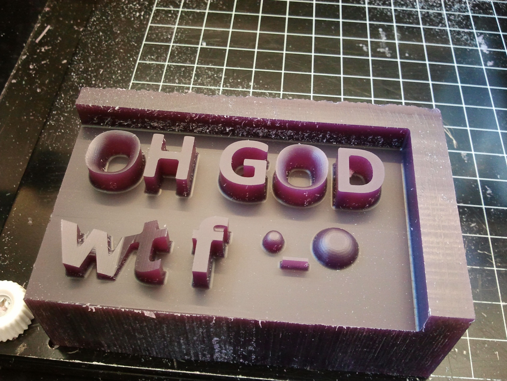
Yeah. Hey, it has flat regions, internal radii, external curves (the o_O is made of filleted cylinders) and some hard to reach inner corners. Perfect! This is what the MP interface looks like. All of the usual CAM-like buttons are there – stock size, faces to machine, and adding machining processes.

For reference, I mostly followed this tutorial. I gave it a read-through, then tried exploring as many of the features as possible without it. Overall, I can say that the software is set up very intuitively and there is a definitely workflow, though the names and labels of functions could have been better translated. Since the software was originally Japanese, I’ll give it a pass for being a little Engrishy.

This is a roughing pass that I generated. MP is interesting in that the feeds and speeds are completely wrapped up in the tool settings. It comes with several built-in tool definitions, and you can add your own. Each tool has a certain feed rate, spindle speed, cut depth, stepover (basically density of those horizontal lines), etc. for each material. So, all you have to do is literally select a tool and indicate your material (which can also  be added custom). I elected to add a 1/16″ carbide ball nose endmill and 1/16″ square ended carbide endmill, using the settings derived from a built-in 1.5mm cutter.

MP also comes with a cute graphic visualizer of what your cut will look like. This is a preview of the roughing cut.

I discovered that there’s not really a way to “zero” anything, like on the corner of a stock. It seems like this machine is intended to cut shallow depressions into a block of material that is of indeterminate size, which – go figure – is what you’d do for a molding and casting scenario. The software even has built in draft angle capabilities and “margin” adding – it will automatically add a ring of full depth cut empty space around your parts.

The machine appears to the computer as a printer. The first time I got to this stage, it would output everything at once, but nothing would happen on the machine side. Some investigations concluded that the Windows side drivers were completely messed up. I had to uninstall everything related to the machine (including its strange USB-to-DB25 cable adapter) and reinstall it in the manufacturer’s recommended order before I could get the machine to perk up. This is what the output screen looks like if you have multiple operations involving different tools. You hit Continue and the machine will run its cycle, then pause at the end and move to a tool change location.

Or, at least, it’s supposed to. I tried a few different settings which may or may not have been the tool change location, but none of them were convincing enough for the machine to follow, it seems. While I had instructed it to go to an unmachined location so I can zero off the next tool, it just stopped at the end of its last machining motion on the roughing pass, which happened to be directly over the sinkhole in the middle of the first O.

Gee, thanks. And I have yet to discover how to jog the machine yet, if it even has that function.

Oh well. Onto pictures of the process.

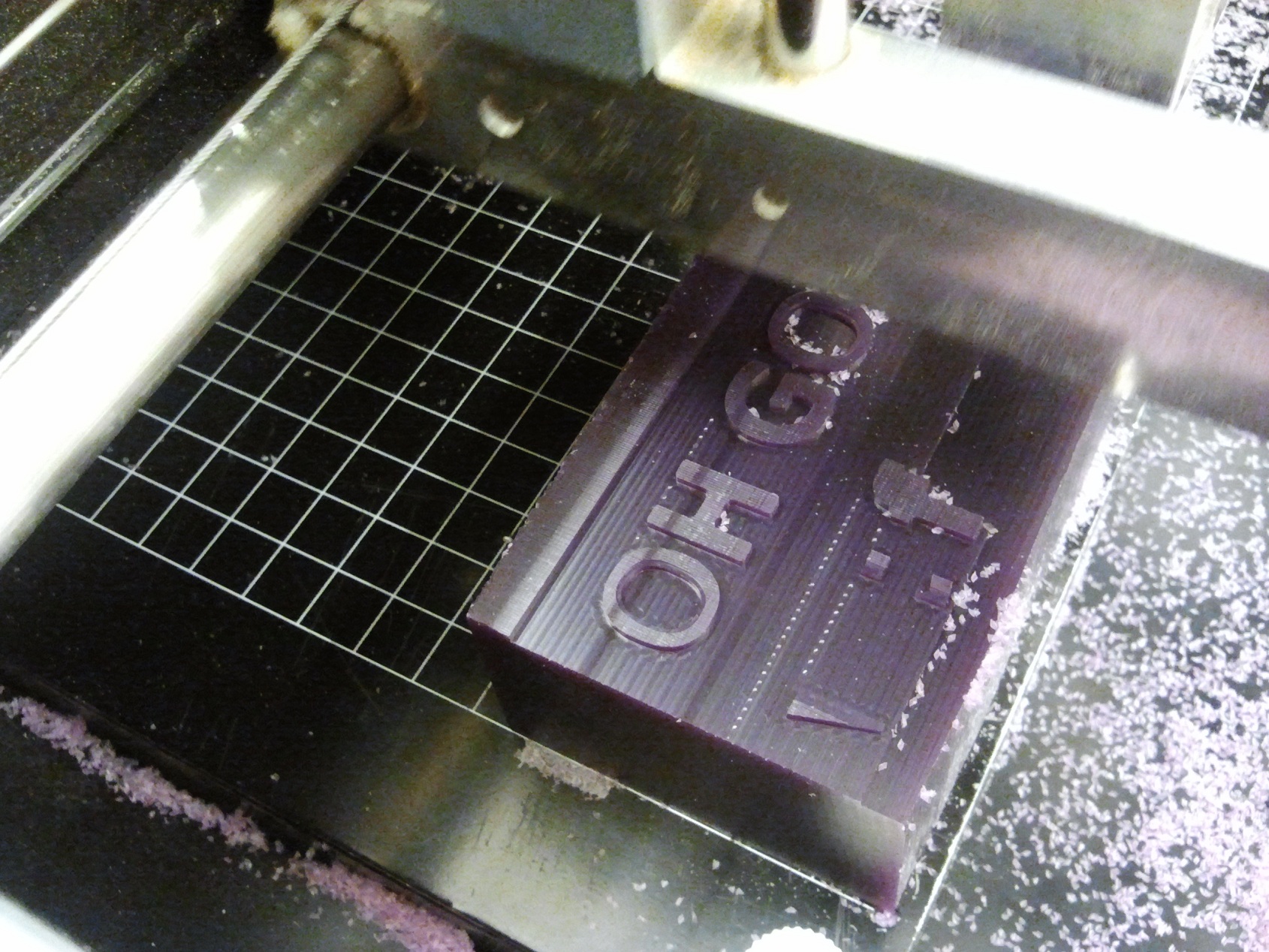
The stock of choice is a little brick of machinable wax left over from the class which I sawed into essentially the right size. You line up the stock visually, on the white grid, and double sided tape is the official work fixturing solution. For the limited capabilities of this machine (which can move at a blistering 15mm/s maximum), that’s perfectly fine. Again, no way to jog and zero or touch off the stock that I’ve noticed.

Z axis zeroing just entails driving the spindle down towards the top of the piece, sticking in the tool, then letting it sort of fall under its own weight onto the material. You’re *supposed* to hit the Tool Up or Tool Down buttons with the tool already in the spindle, but that only increments in 0.1mm as far as I understand.

After the roughing pass completed, I changed the tool in the machine by moving the tool up until it was well clear of the material. Unfortunately, as mentioned before, I have yet to discover how to make it go to my big unmachined margin to the right so I can properly touch off the finishing tool, a 1/16″ ball endmill. So I eyeballed it.

It was pretty good eyeballing – the tool was too low by about 1/2mm. Either way, modeling wax is very, very permissive about how it is to be machined.

The finishing stage took approximately 6 or 8 hours, and ran overnight. The finish in the end was very, very clean. Like so clean. Way better than any 3d print can ever get me, for sure!

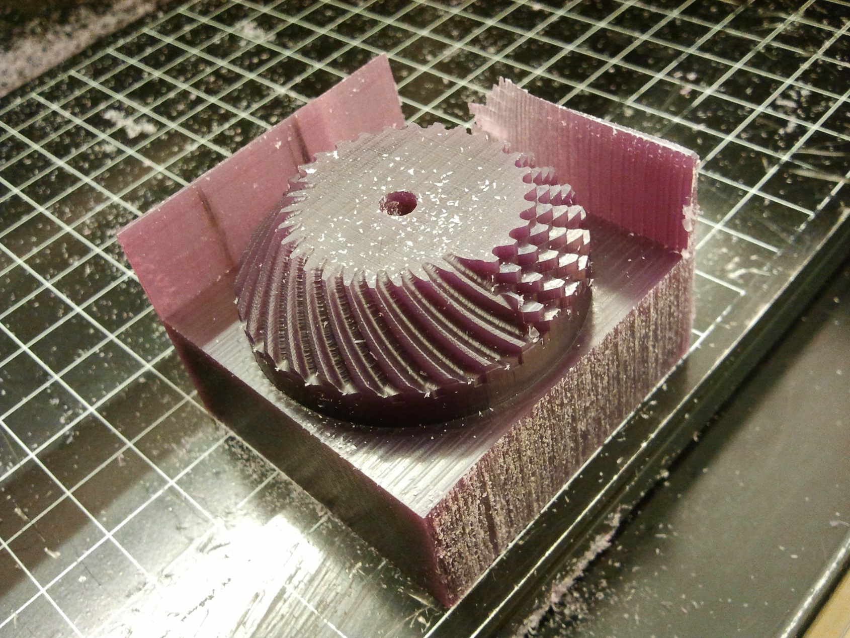
I decided to try something a little niftier, closer to a part I’d design and then export as an STL. I downloaded a spiral bevel gear from Thingiverse since it looked pretty machinable and was much more complicated.

This time, the path generation was a little more complicated. There’s no way in the software to say “skip this feature since your tool is too short to machine it”. Instead, you define specific rectangular regions to machine – the default is the whole part – that get pathed independently.

To avoid the through-hole in the middle which would have been too deep for the finishing ball endmill, I therefore had to make 4 rectangular regions which very carefully avoided the hole. There’s no “boolean difference” allowed in this operation.

Here’s the piece during one of the finishing passes. I ran the cutters faster this time, so some of the non-rigidity of the machine is visible in the gear teeth. I also set the margins to be very small and mismeasured my wax chunk, so it machined off most of its own sides anyway. I again couldn’t get the machine to go to a specific spot for a tool change. I must be misinterpreting what it means by “Tool Movement Location”…

I intend to keep experimenting with the machine in the coming days. The machine, sadly, does not talk in G code. Rather, it uses RML, which is Roland’s own little language. There seems to be an avid community of modders that replace the controller inside with a custom board that can interface with commercially available CNC driver software.

I  see how this machine can be very helpful and intuitive for model makers and designers who don’t have an engineering background, and I definitely see how it would be useful in making super fine molds for casting plastic parts. What I’d like to get squared away in the next few days is how to persuade it to go to a known spot for a tool change, something which the Media Lab tutorial I linked to at the start seems to hand wave. Once that’s done, then I will definitely consider trying a few actual molds. Maybe it’s time to stock up on that high density polyurethane board stuff…

However, I definitely should play with the EZ-Traks some more. I think my preferred realm still leans towards using a machine with more cast iron.