Did you know that I only have 2.5 weeks to finish Ãœberclocker? I technically do have a whole month until Dragon*Con, but only 2.5 weeks remaining around 24 hours of machine shop access and piles of potential parts. Back in the dayâ„¢, I’d have to plan for weeks to take advantage of a few hours of machine work at most.
I’ve been totally spoiled by machinery. Hey Dale, I think I’ll just camp out in your shop space when I get back.
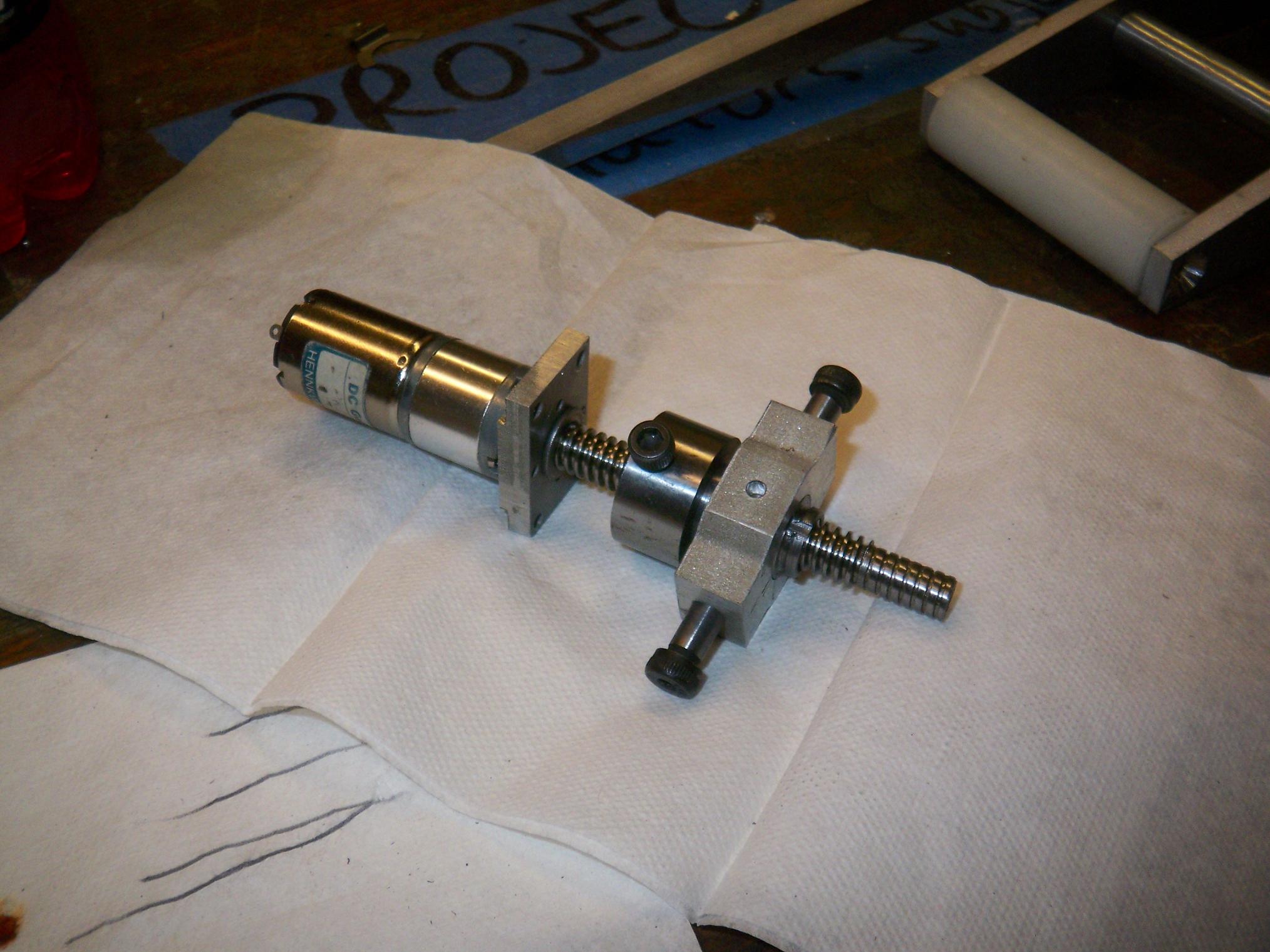
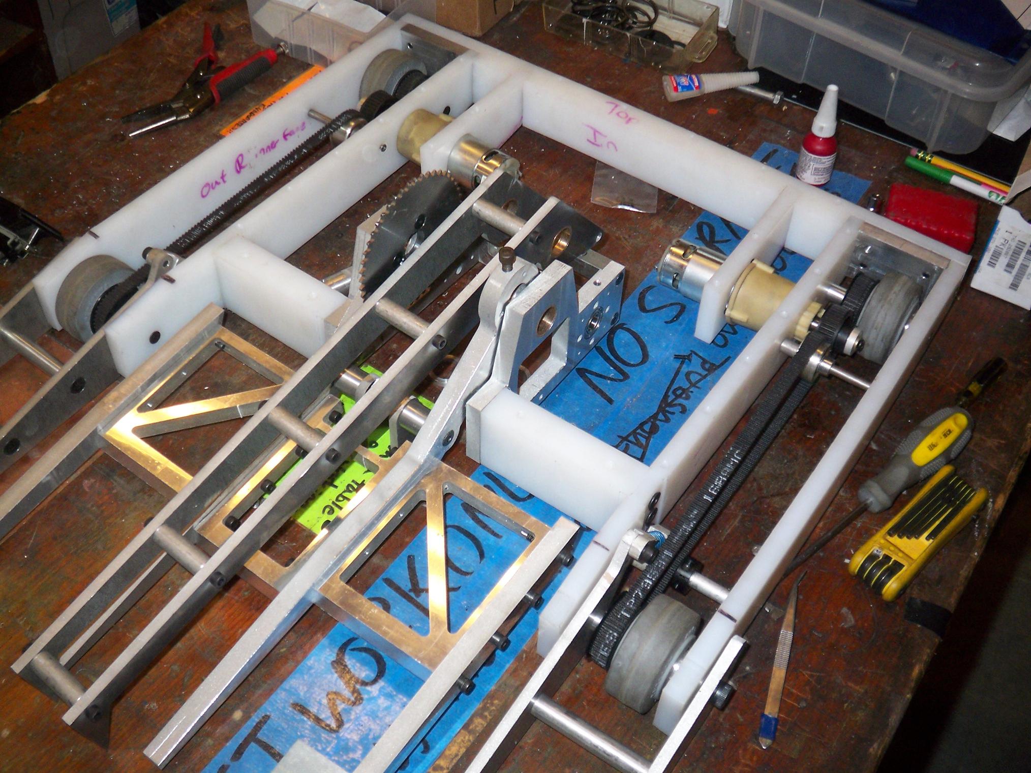
Anyways, work is shifting towards completing the fr0k assembly. The frame and running gear, at this point, is complete, since I recut the bottom plates a few days ago. One of the fr0k gearboxes (the so-called “überghettofrakenb0xen”) is complete, and the other is coming. The fr0k actuator awaits springs from McMaster. After that, it’s all electrical work.
And Pop Quiz needs a blade. Like, now. But, first, Ãœberclocker.

I lied when I said the frame was complete. I got these Mabuchi 700-frame motors from Banebots and plan to swap them into the drive gearboxes when it comes time. Although this is not a priority, I would like stronger drive motors for Ãœberclocker if I can manage it.
Two 500-size drill motors, while punchy for a 12lber, is cutting it close for a 30lb ‘bot which needs its drivetrain as part of its weapon. Especially carrying another opponent – a gross weight of 60 pounds – the drive will be heavily stressed.
The motor swap should be relatively simple. Some drill gearboxes (not sure about these yet) already have the mounting pattern for the larger motors built in, as some 18 volt drills do have these larger-sized motors. The 15 tooth pinion on the 900RPM gearboxes have plenty of beef to bore to 5mm.
If not, I’ll just modify the motor mounting plate. I would get a few of those drills from Northern Tool to play with, but the two-stage gearboxes require a redesign of the back half of the bot. Not smart when the back half of the bot is already made.
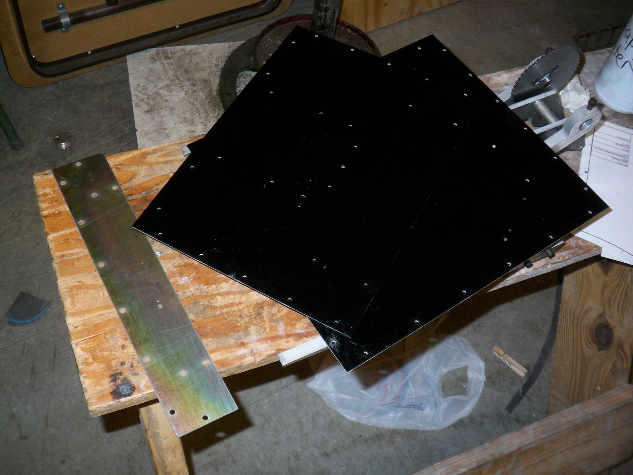
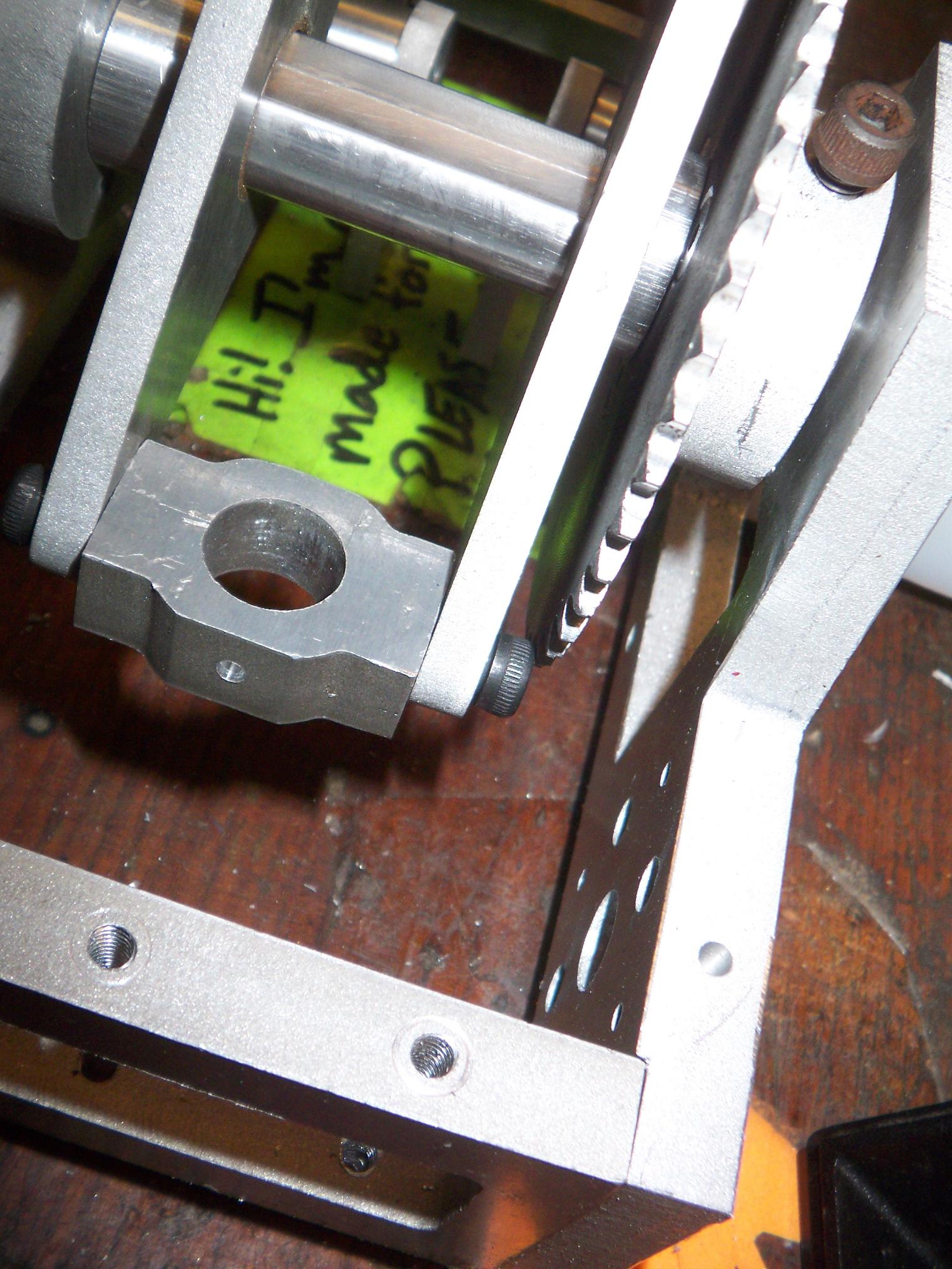
Top and bottom plates. The top is from several weeks ago (the only part out of like 10 that the jet didn’t eat), and the bottom two are new. I made the rear bevel armor out of some .075″ steel for added protection and mass (though it’s still under a pound).
The steel is also dichromate plated, which gives it the weird rainbow effect. It doesn’t speak much to Ãœberclocker’s masculinity to run around with a giant rainbow-colored ass, but makes it all the more funny when it defeats opponents.
The garolite holes have minimal delamination. I found that the best way to avoid it is to just punch the hole and cut as fast as possible, essentially completing the hole before the high pressure water has time to force the laminations apart except in a very localized area.
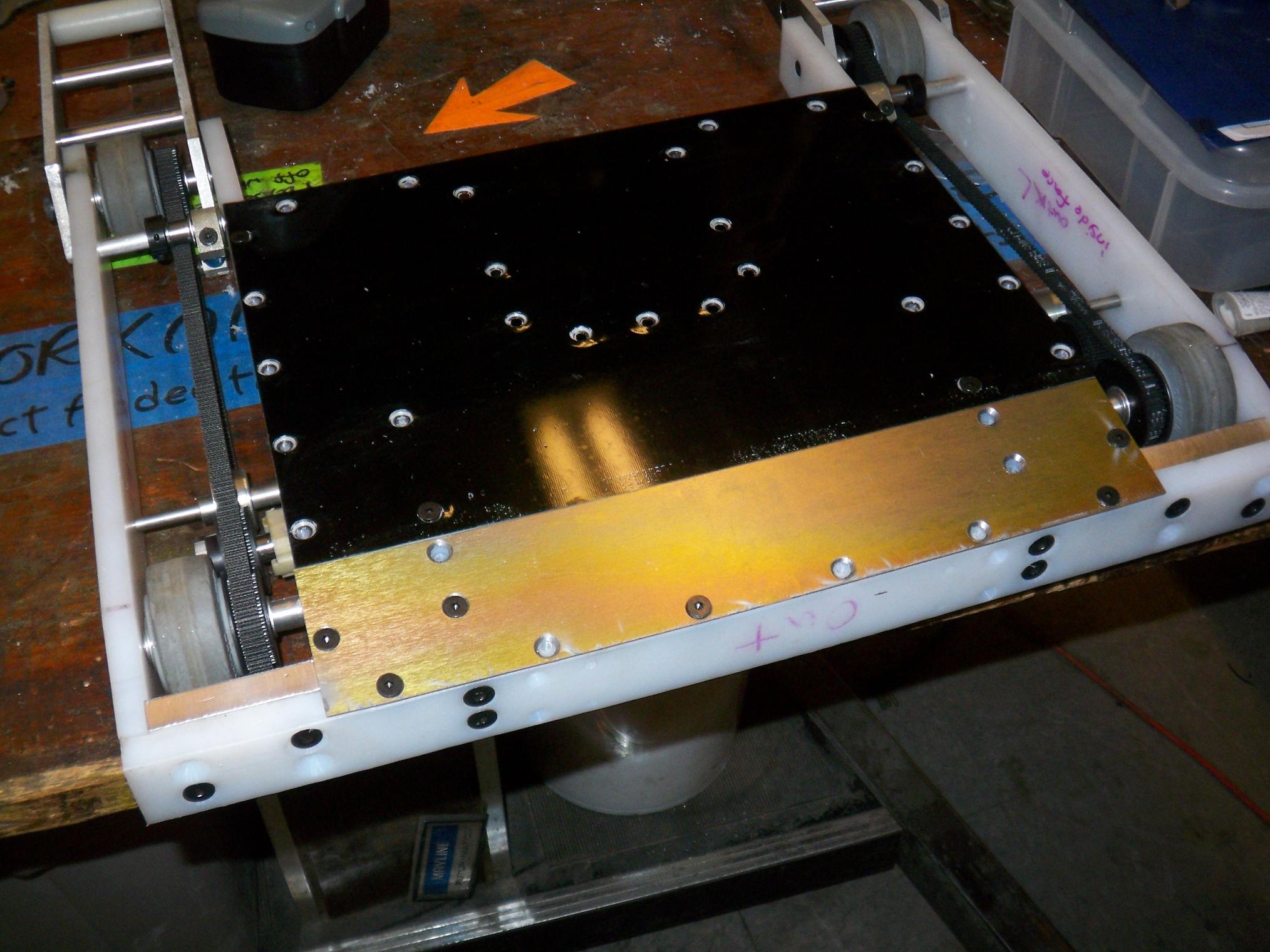
And here they are mounted. Not all the holes on the beveled end line up (due to sketchy geometric projection and even sketchier edgefinding), but UHMW is pliable enough and the error small enough that I just let the countersunk screws align themselves.

Freshly gutted drill gearboxes lined up like freshly butchered meats.
It takes three drills with metal gearsets to make two überghettofrakenb0xen, since each one uses three planetary stages. I needed to swap the 15 tooth pinion on the 18v motors for the 9 tooth pinion on the not-18v motors.
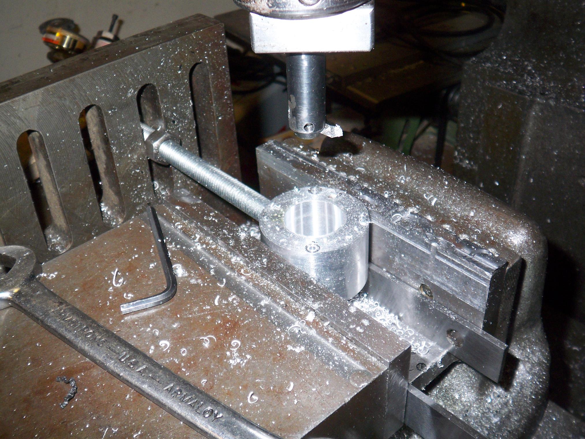
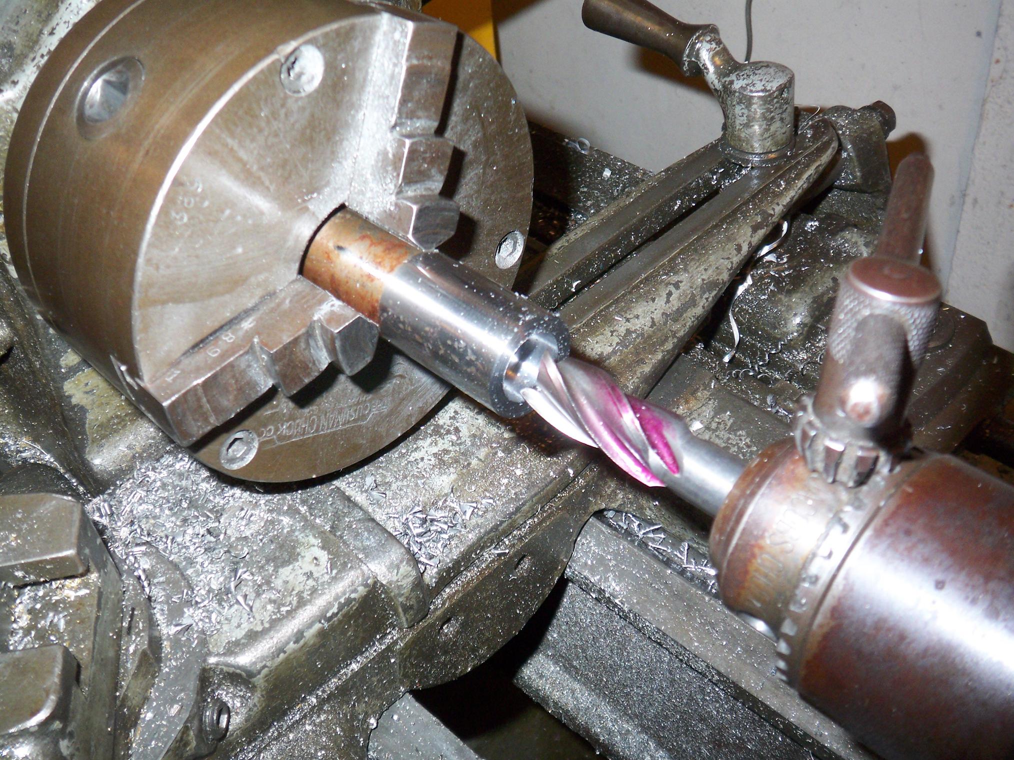
Making the aluminum gear housing for the ÃœGFBs. To do this, I made some 2″ diameter, 1.325″ long cored rounds on the lathe, then finished on the mill (since there isn’t a proper boring setup for the lathe). The boring head is my new favorite tool.
I machined a light flat onto the casing before starting – this is so a plain milling vise with no V-channels can grip the round part effectively. Also it was to ensure I can remount it in the correct orientation.
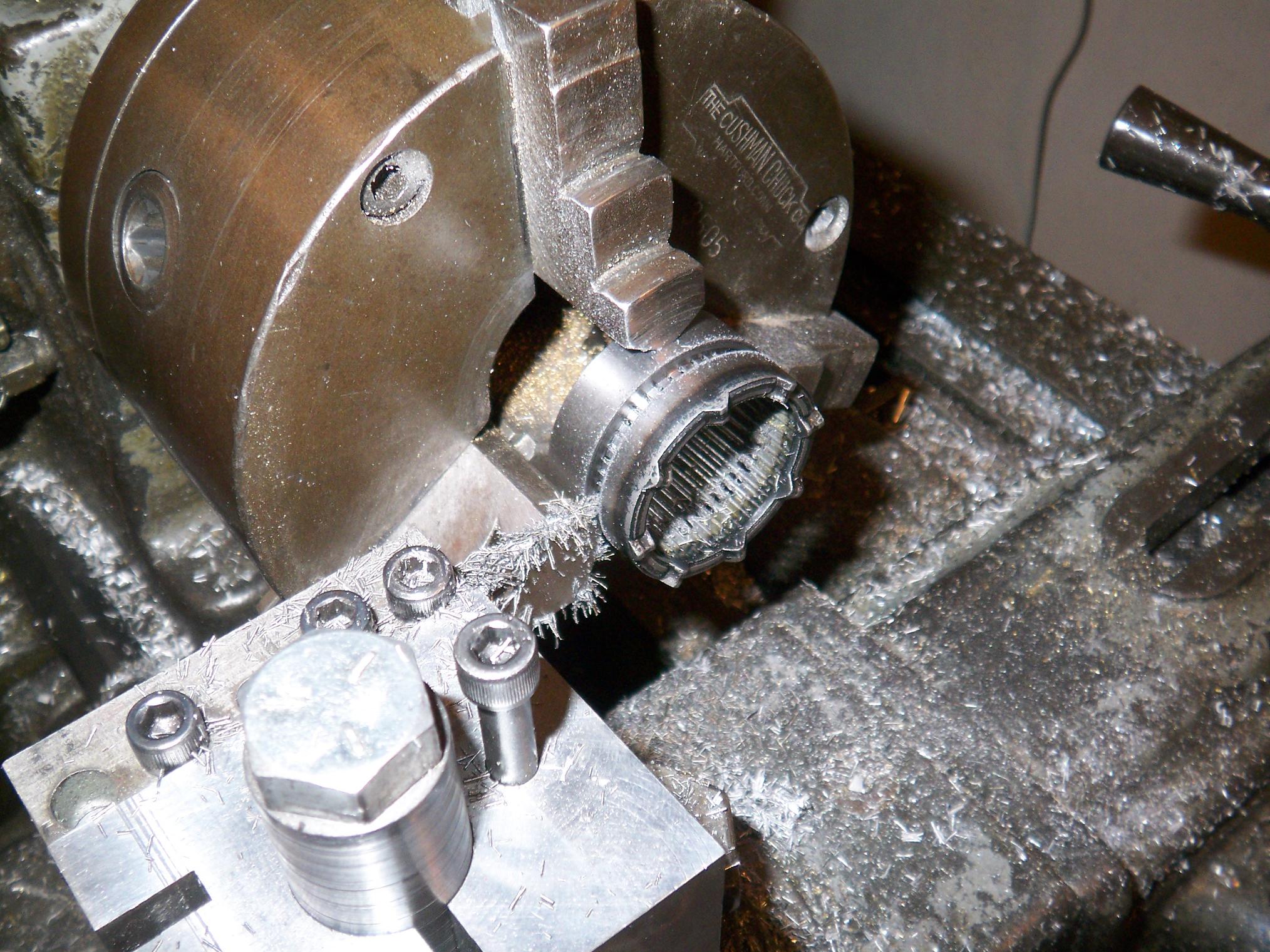
Sectioning off a drill ring gear to use as the first stage. Being made of sintered steel, it absorbed alot of oil from the grease in the gearboxes. Result: dense grey smoke cloud, but the self-lubricating is nice.
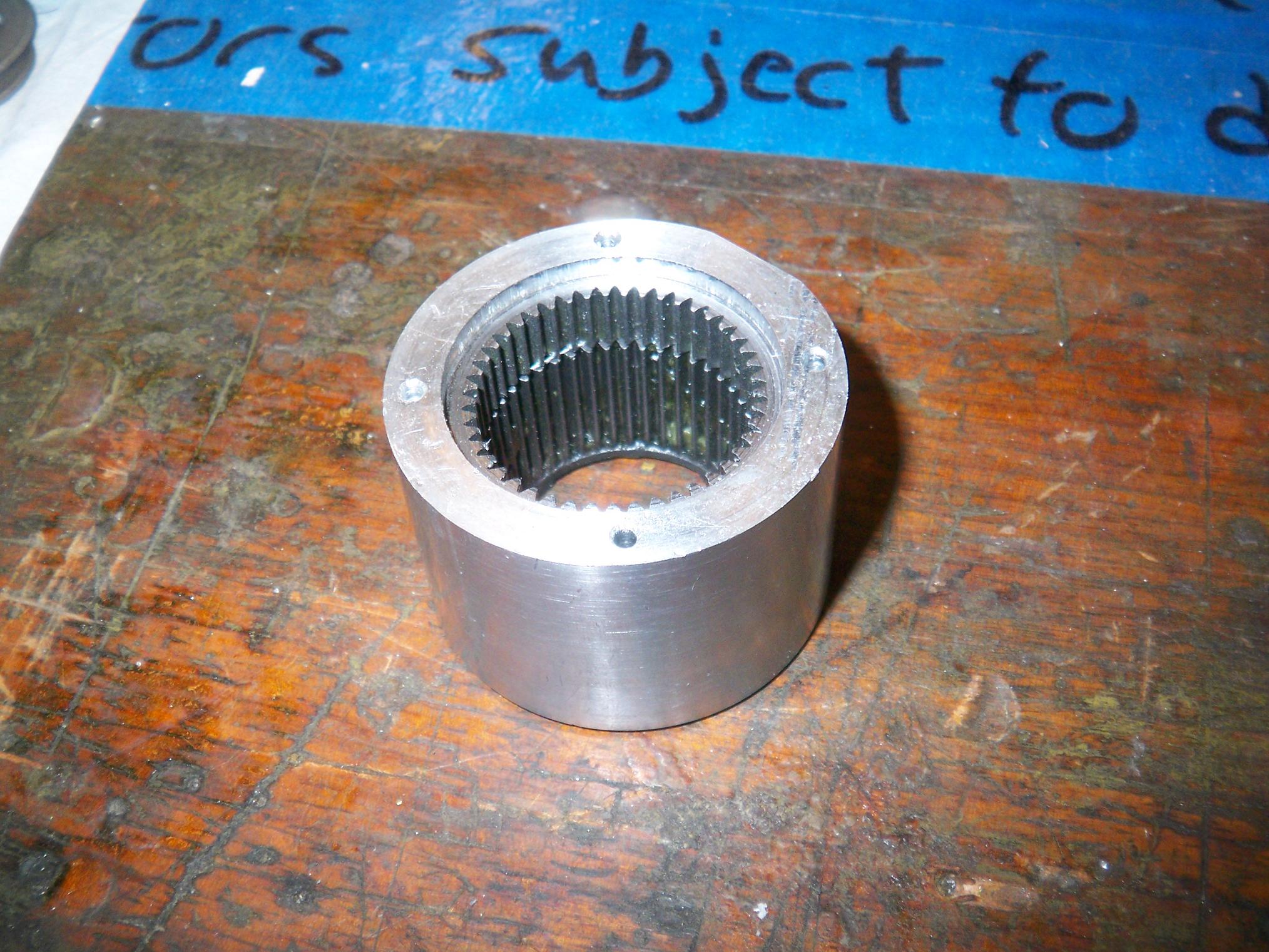
And the ring gears installed. I (not purposely) used a massive, massive press fit for these parts. The drill ring gears are 1.495″ in diameter. The hole I bored was supposedly 1.490, but turned out to be 1.485… It took a very, VERY large torque bar in the vise and the grace of the Robot Gods to squeeze these rings in.
There’s a tiny bit of offset in the teeth between the half-ring and the intact ring, but that doesn’t affect anything, since the first stage fits fully in the confines of the half-ring.
I anticipated having to use set screws or something to keep the ring gears from rotating under high-torque loads, but if they let loose now, something has gone horribly wrong. Although this giant press fit was accidental, I’ll probably reproduce it for the other ÃœGFB

In a moment of genius (or perhaps insanity), I discovered that the chain breaker tool acted as a nice gear puller for the drill motors. It worked on the 15 tooth pinions fine, but did not on the 9 tooth ones.
Two gigantic flathead screwdrivers came to the rescue for that.
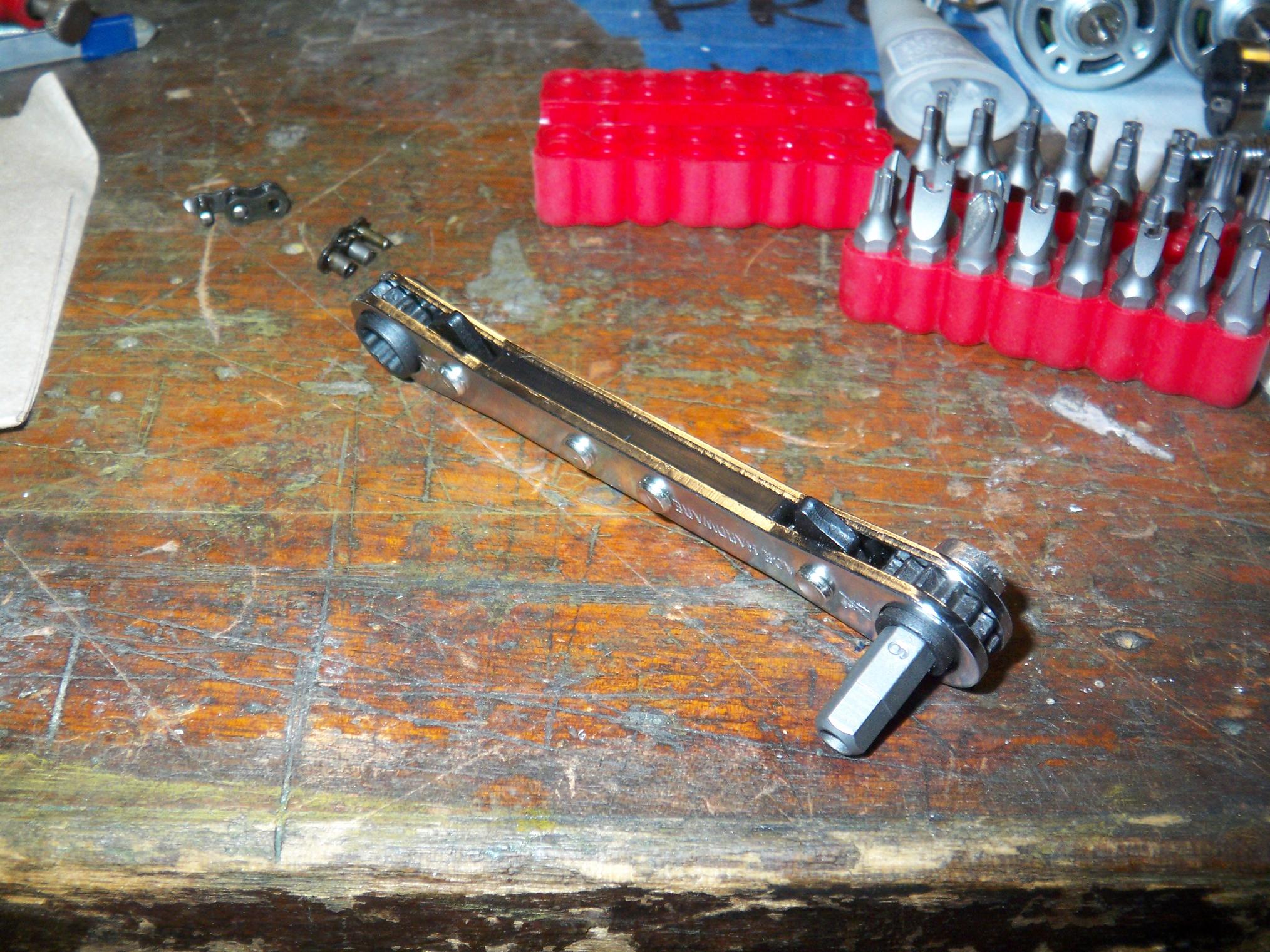
In another moment of insanity, I discovered that sticking a magnet on the end of a ratcheting 1/4″ box wrench made a very low profile right-angle driver that takes any 1/4″ hex screwdriver bit.
I’ll probably permanently epoxy the magnet onto said box wrench later on and press this into service as my “I-suck-at-designing-serviceable-machines” tool.
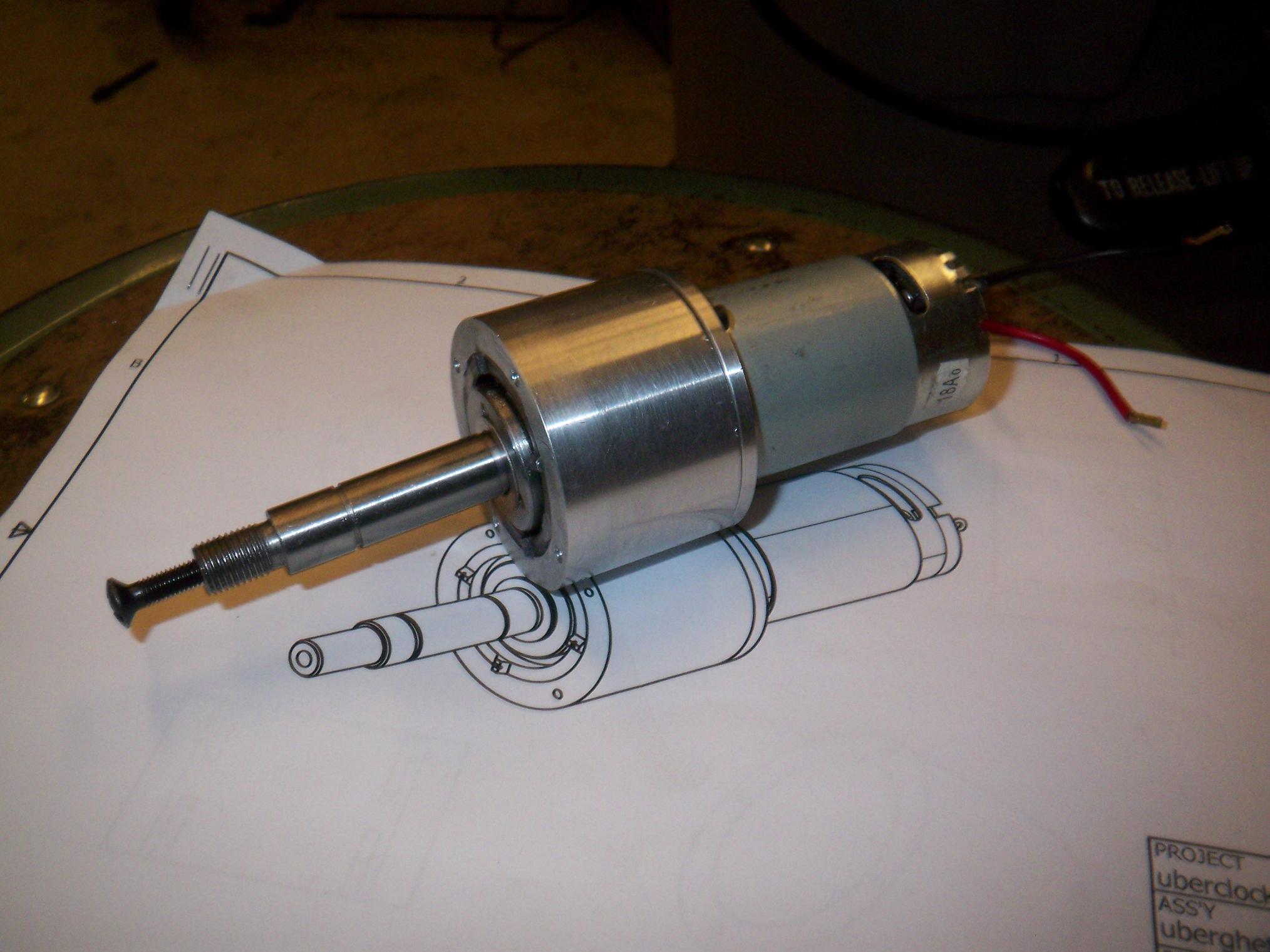
The basic form of the ÃœGFBs. These are not independent assemblies – they are designed to mate permanently to the fr0k main support towers.
A serendipitous side effect of cramming the drill ring gears into a space that was .6% too small for them was actually increasing the precision of the gearboxes somewhat. I noticed that I had to align the gears more before they’d drop into their pins, and the whole thing has less backlash and “wiggle room”. Presumably the slightly too-small ring gears cause more tooth contact – this is a good thing.
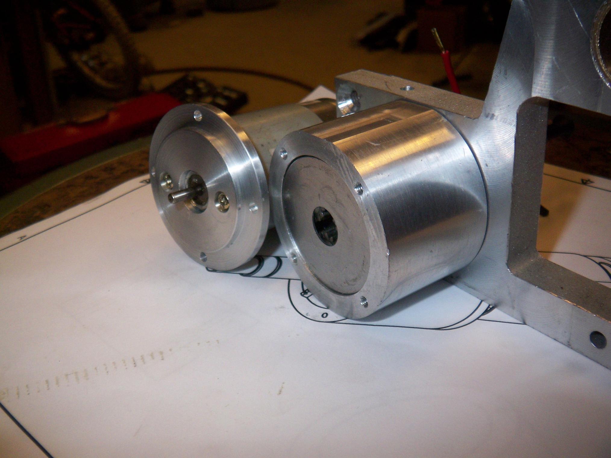
One small issue arose from the fact that I never fully measured the inside of a drill gearbox – only speculated on the length of parts based on the ring gear dimension. This was fine when I was making housings for stock two-stage gearboxes, but adding the third stage threw off my width calculations.
Result? Pilot ring on the motor mounting plate doesn’t go all the way into the ring gear housing. In fact, it barely goes in at all. The gearset sticks out so much that it’s better to leave the mounting plate flat and let the remaining space be “wiggle room”.

….so I turned the mounting plate around. I actually did make a new one, since the motor mounting holes had been counterbored halfway through. Now the ÃœGFB is a nice fit.
And I need more 4-40 cap screws, but the hardware store isn’t open this time of day.