Tonight was a night filled with little round things.
After re-engineering the gearbox output shaft 3 times (all at around 4-5AM, mind you, so nothing may have changed) I settled on a solution that was simple, didn’t involve custom threads, and could be easily adjusted. Even better, it was composed mostly of off-the-shelf parts.
What was handy was the discovery of the FEA tool in Inventor, which had actually been staring me in the face for the past year without me noticing. This tool allows the user to simulate load conditions and analyze parts for stress.

Here’s a neato screenshot showing the output shaft in an (exaggerated) loading state. It didn’t tell me too much this time, since this is a pretty simple part. I’ll probably find this tool very useful in the future, however.

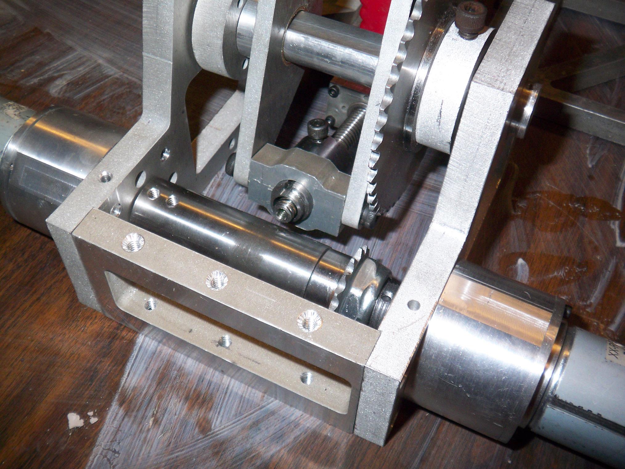
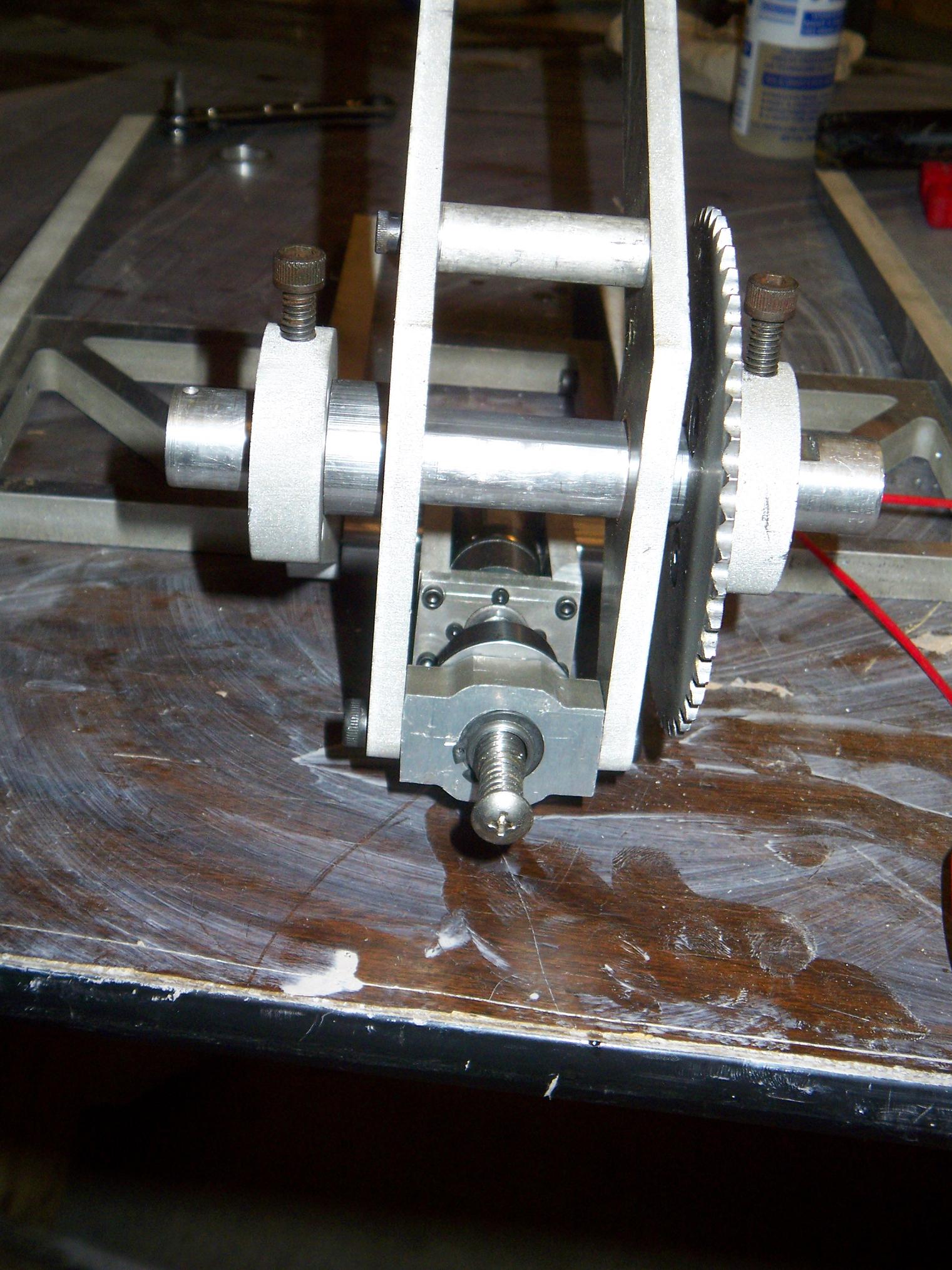
So here’s where it goes. The sprocket is solidly attached to the output shaft, and giant shaft collars clamp the split ends onto the individual drill gearbox shafts. Clutch action has been moved away from the sprocket and into the shaft collars. The upside is that the “clutch pressure” is adjustable without affecting the position of any parts (as opposed to advancing a nut up and down a thread). The downside is a smaller contact radius. We”ll see how this works out when I test the thing under power.
The little narrow part in the middle is to clear the clamp leadscrew. Stress riser it may be, but mind you, it’s still solid 5/8″ steel.

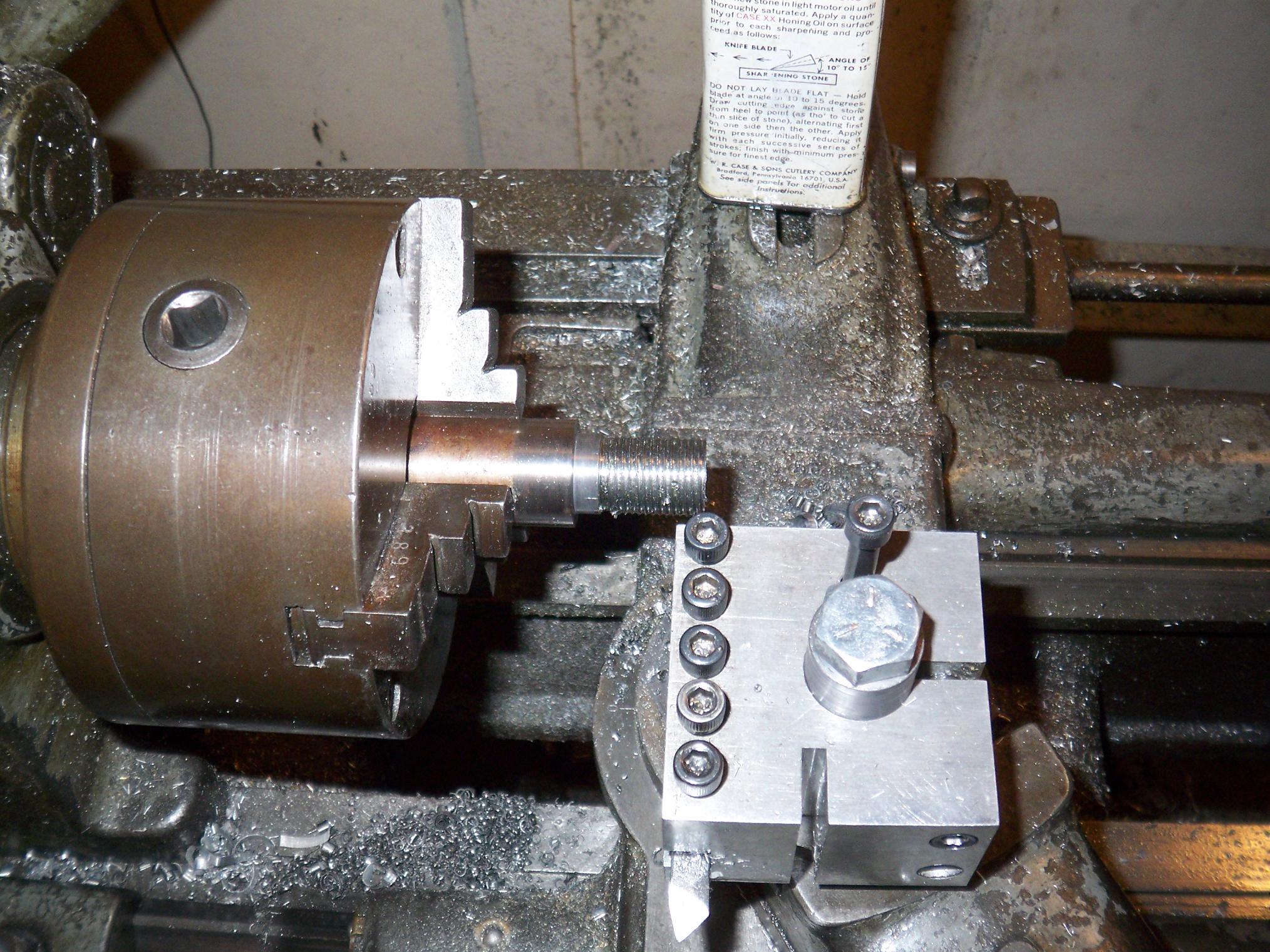
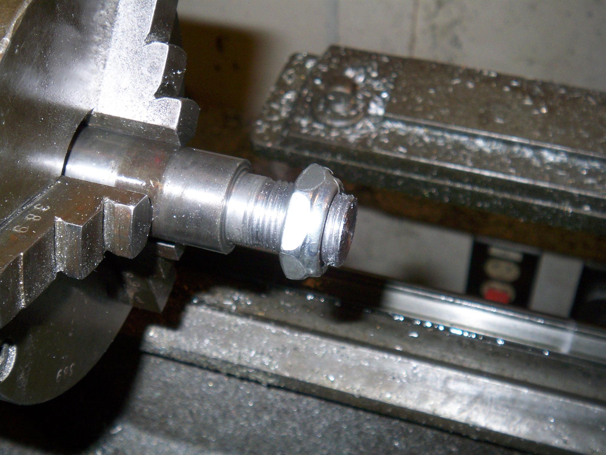
Here it is implemented. I found a Convenient Rod of 3/4″ Mild Steelâ„¢ and made the appropriate machining motions to coerce it into a shape resemblind the 3d model. The shaft collars are McMaster stock.
Even though McM is about 5 hours away now (in New Jersey), I still manage to get next-day delivery. This is because they are fucking awesome. In fact, the packages are usually stuck longer at the receiving area than in transit. I have begun to bug the desk people the day after I place an order – and my stuff is always there.
They have, in turn, begun to set my stuff aside from the rest of the pile because they know I’m coming.

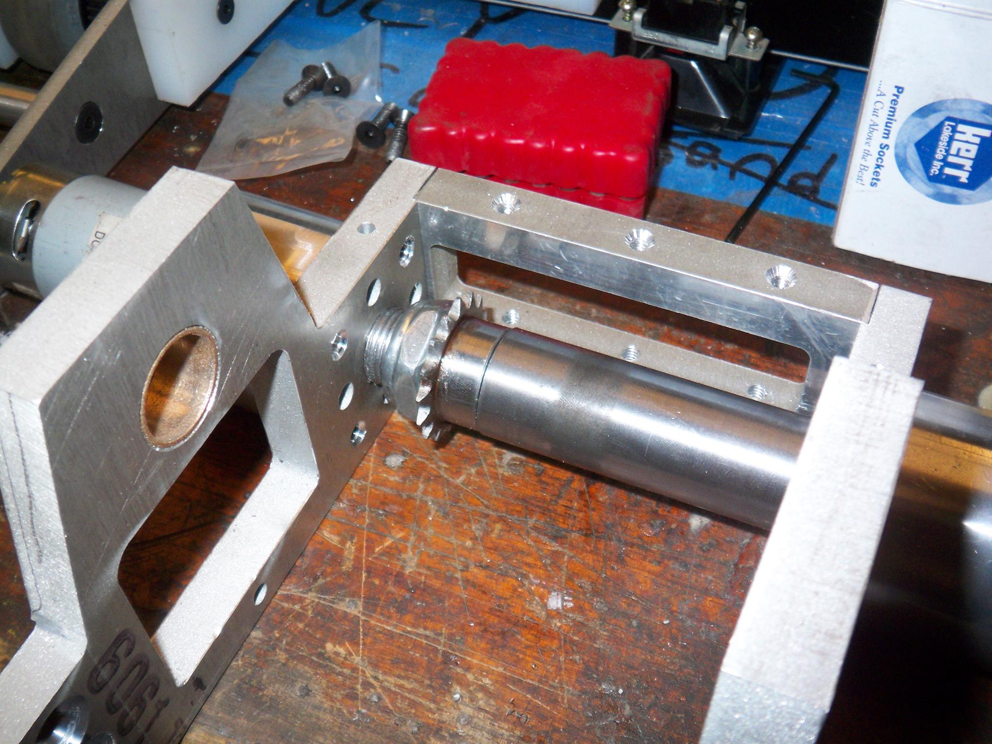
Here’s the sprocket attached to the shaft. I wanted a removable attachment method, so dowel pins were ruled out. I considered giant set screws and flats, a third giant shaft collar, and even ghettokeying the sprocket, but all of that was abandoned when I discovered these weird screwpins. They’re known as “dog point” set screws, and are half pin, half screw.
Hence I could thread the screw portion into the sprocket, but the bottom half acted as dowel pins to transmit the load.

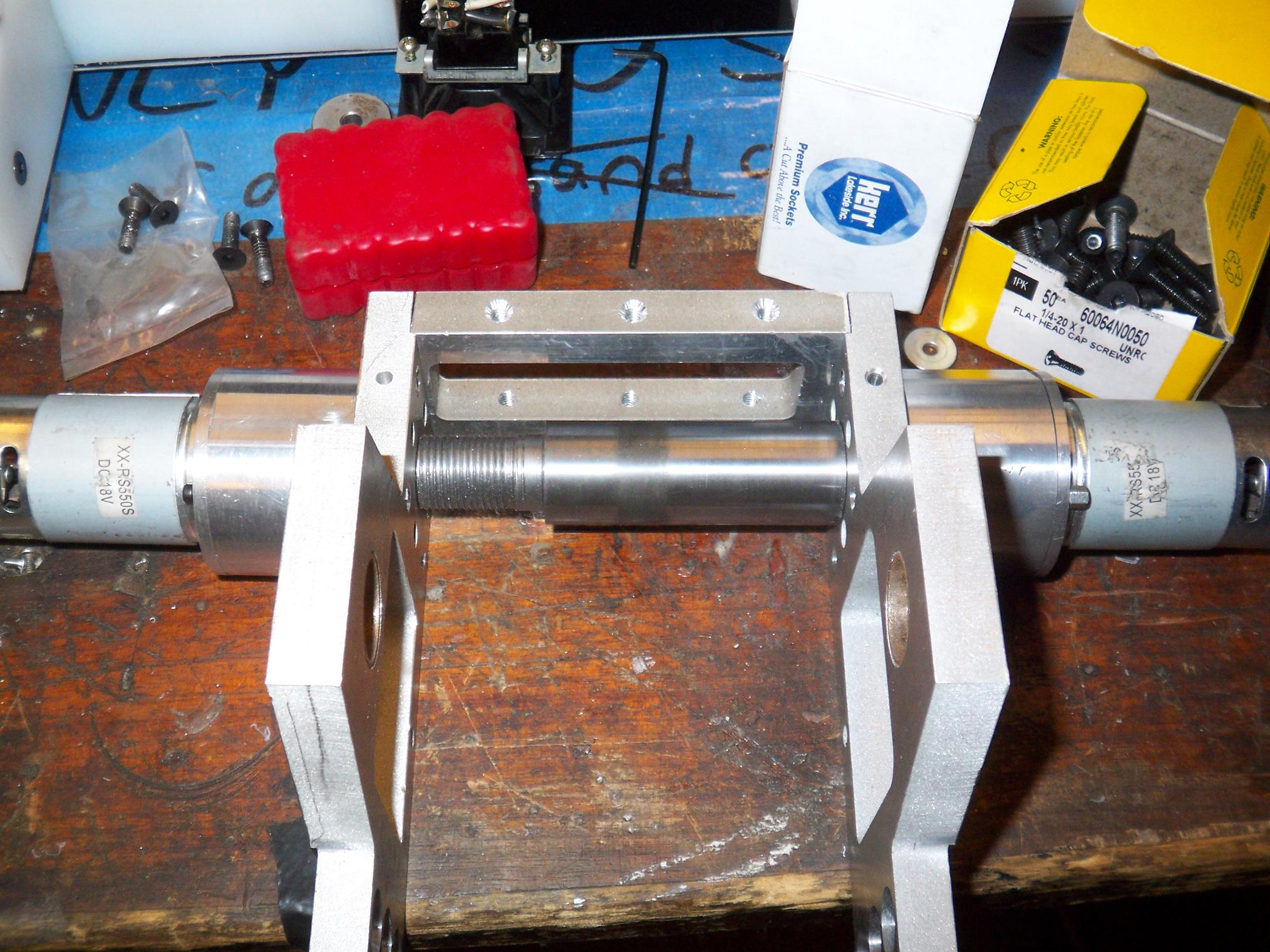
The completed output axle. Sadly enough, I found out that I had no way of cleanly machining a thin slit into a part – there wasn’t a way I could somehow wiggle this into the horizontal bandsaw sideways, and the large vertical bandsaw has a coarse woodcutting blade. I could have milled a slot, but the minimum width was 1/8″ and it would have taken forever (tiny cutter, steel… etc).
And so I had to take a Dremel with cutting wheel to my shiny part. Thus is life.

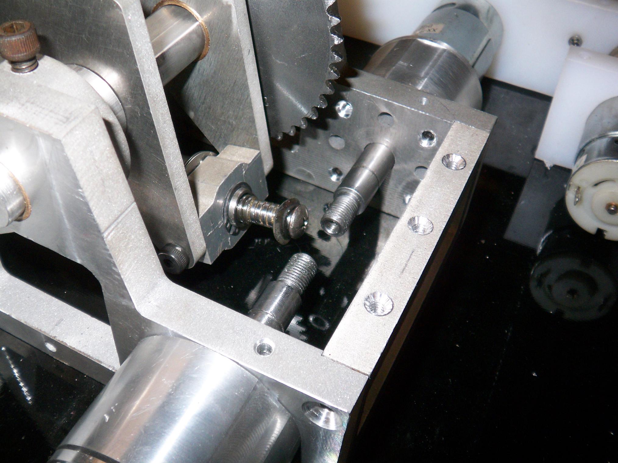
Oops, it looks like I bored the hole off center.
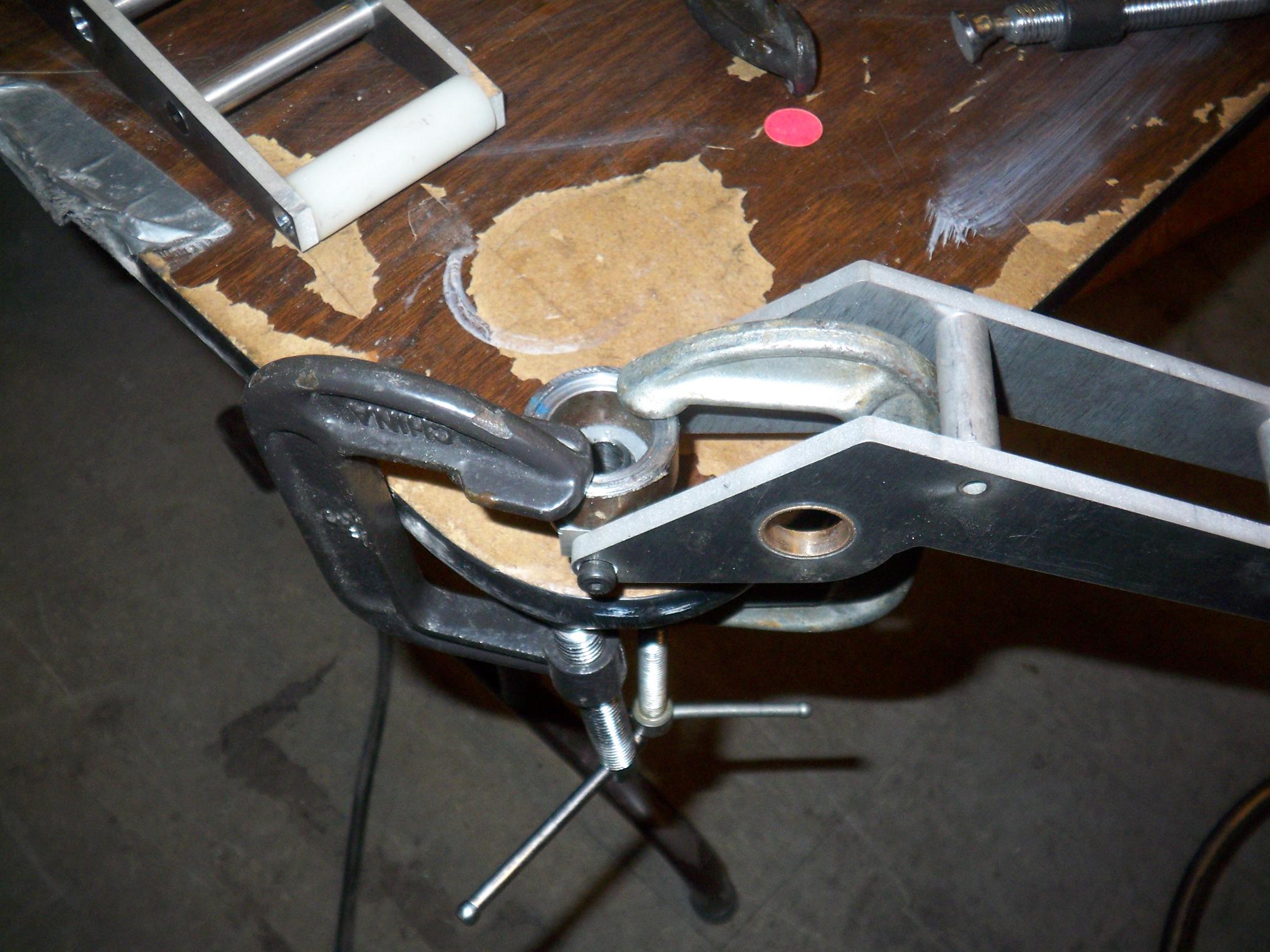
Actually, this is the second half of the plan for giving the clamp leadscrew more clearance while improving lifting efficiency. It is possible to “move” a misplaced hole over a small amount by boring it larger and offset in the direction you want to go. For instance, this 1″ diameter hole is shifted to the right of the original 7/8″ hole by 1/16″. Using a thicker bushing would then move the axis of rotation over to the center of the new hole.
This 1/16″ gave the leadscrew enough space to not hit anything when the clamp was in its maximum extended position.

But merely shifting the hole was no fun. If I had to make the hole bigger, then I was going to go to rolling-element bearings. Bushings are nice and simple, but one nanoarcsecond of misalignment and they bind, seize, and gunk up, especially on an aluminum shaft.
Metric ball bearings come in a wider size selection than inch. This selection also includes some very low profile bearings. For trading up to a 26mm hole, I could have a 17mm bore ball bearing that was only 5mm wide.
And so I also got these little ball bearings. To install them required the 26mm offset counterbore as well as turning down a bit of the fr0k shaft to 17mm.

What would I do without the boring head… Probably not much. I used it to give the bearing pockets that nice “Loctite Finish”.

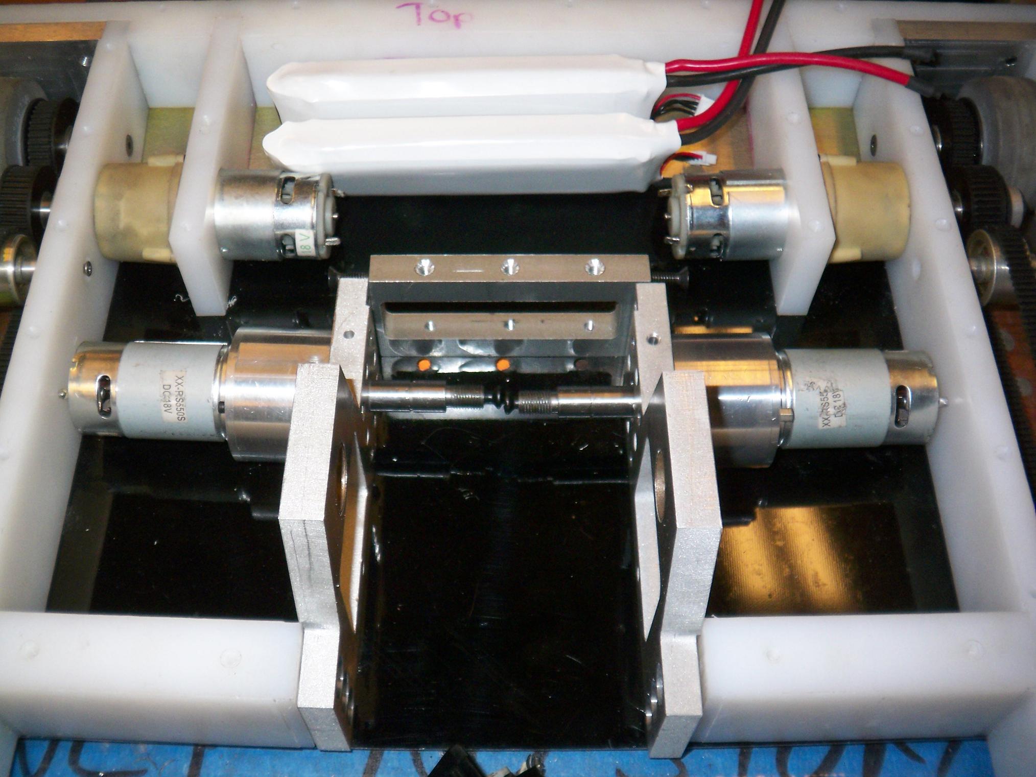
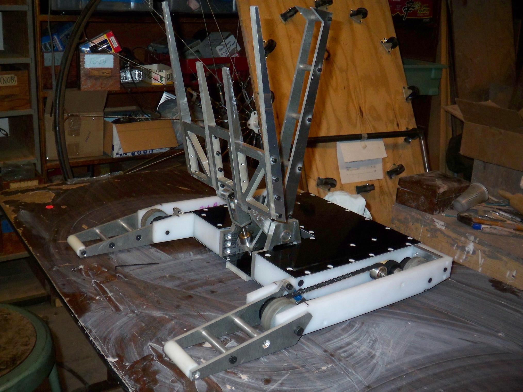
So here is one fully assembled side of the fr0k base, one Ãœberghettofrakenb0x mated to a freshly ball-bearinged fr0k tower.
Note that I cut off the 3/8″ thread from the drill shafts, since the design didn’t need them.

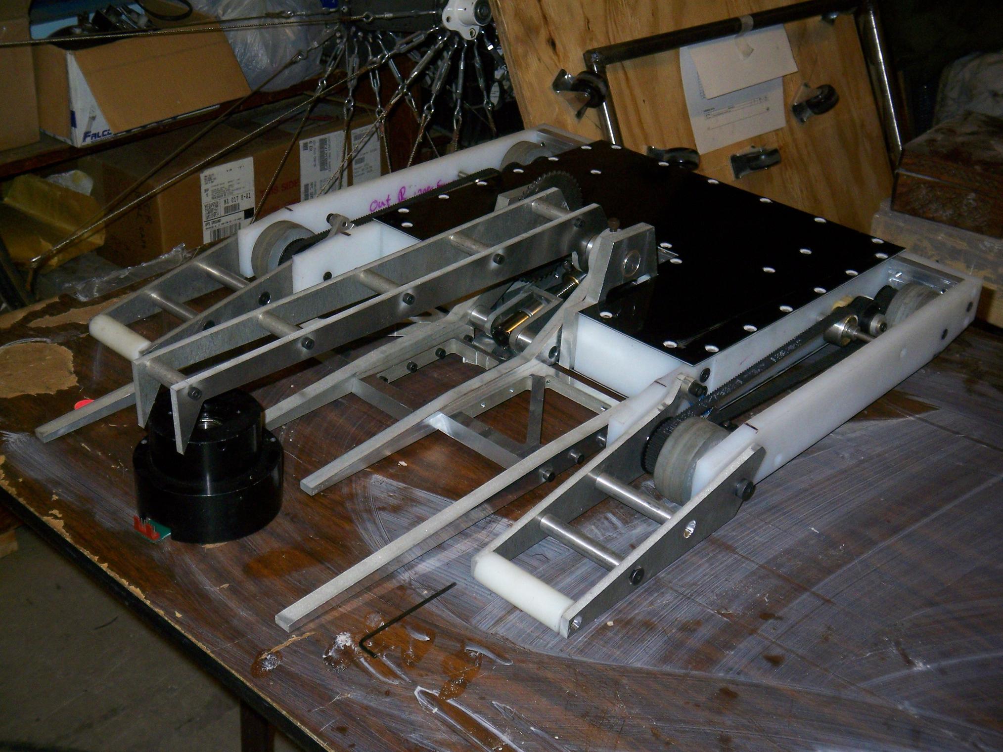
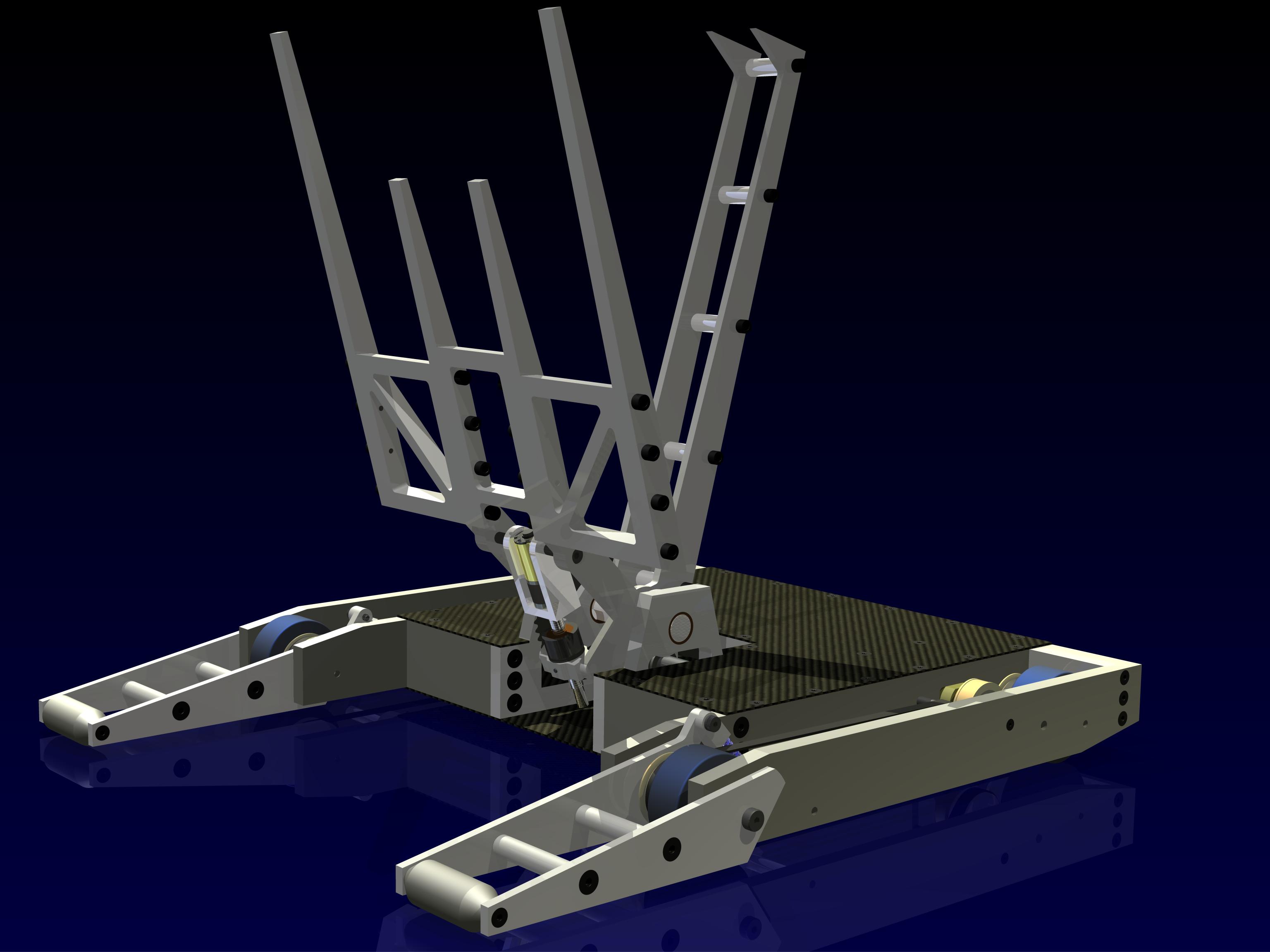
Here is the fully assembled and complete fr0k module. It weighs around 8 pounds.
Each drill motor runs through its own 216:1 gearbox to the common output axle. A further 3:1 chain reduction brings the final geardown to 648:1 with an absurd amount of torque.

Add in the #25 chain, and now here is the first non-rigged Pretend-O-Bot. Yes, the fr0k is hanging in the air on its own.
I cannot backdrive the motors even with the long lever of the forks (well, at least not without clamping the entire frame to the table and then leaning on it). This is good, because it means the motors have to exert no effort (consume no current) to actually keep a 30lber in the air. I had designed the system such that the motors wouldn’t be overtaxed even if they had to be under a small amount of power, so this is encouraging.
The chain drive might need a little work, since the optimal chain length is 60.25 pitches of #25 chain. I can’t actually have a quarter of a link, so I had to use 61 links. This extra 3/4 link adds alot of slop to the system, and I’m concerned about the chain jumping under heavy loads.
But what does having a fully assembled fr0k module mean? It’s time to test the powerlifting ability. Since I had already dropped the module into the frame and made it look all nice and taken pictures, I decided to save this for another day.
Like today.