Project RazEr: It’s (99%) Legit.

Update:Test video! Now it officially exists. Low speed only for now, since I b0rked the controller and stuck it in Sissy Modeâ„¢

After eight months of development, five of which were spent sitting on a shelf at MITERS, Snuffles Reloaded finally moved under its own power. And boy did it move… I have already managed to nearly faceplant once on it.

With the project having entered a state of semi-functionality, and with it standing a decent chance of becoming something worthwhile, I’d like to move onto a less whimsical name. While “Snuffles” was cute, it just doesn’t have that aura of coolness.

Okay, so “RazEr” doesn’t either, and the coolness of a Razor scooter maxed out some time in the year 2000. But see what I did there? It’s an E! Instead of an o! For “ELECTRIC”! And it’s a Razor scooter! Get it?? INNOVATION!

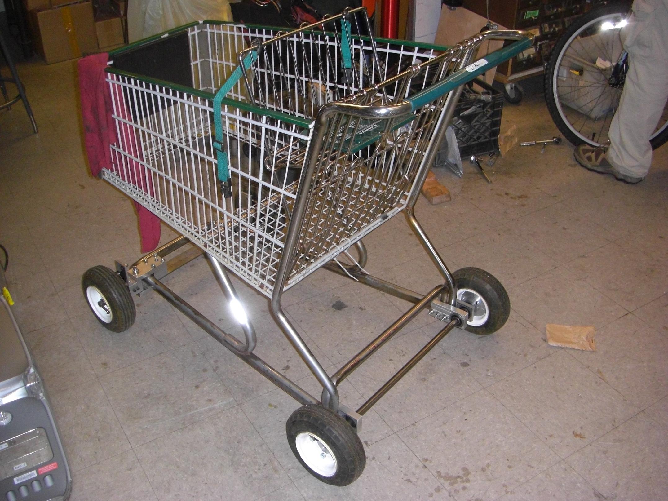
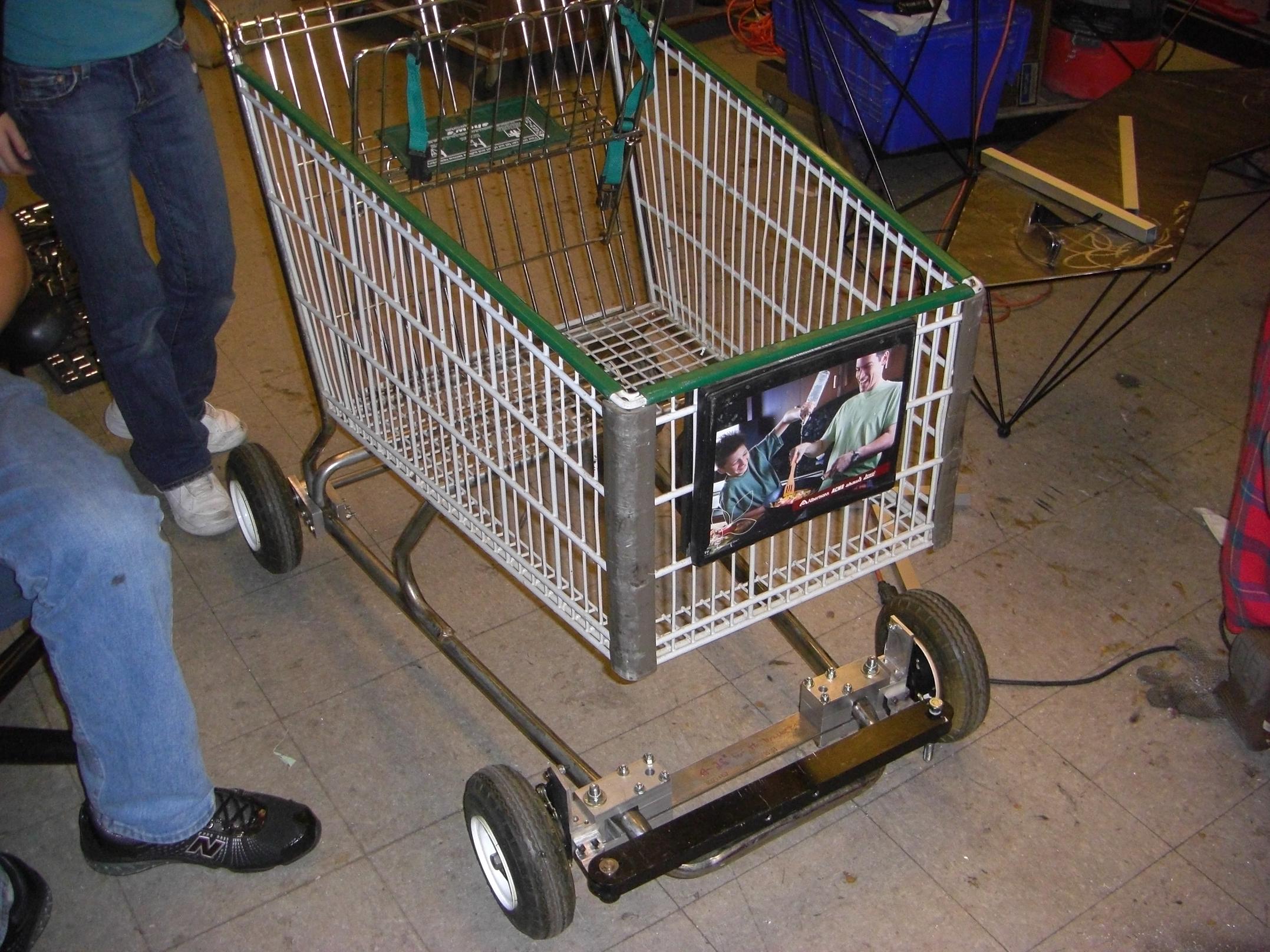
Without further ado, here’s the 99% finished vehicle.

Yes, that IS a small, amorphous blob of wire and circuitry duct-taped to the steering column with a knob on an equally duct-taped stick acting as the speed governor!

No, it’s not spring returned. It’s cruise control for cool. Without caps-lock, and potentially more blood.

I finally mustered up the effort to pull it off the shelf and hook up the last four wires remaining on the thing which had kept it from moving for the past few months. With the help of some friends, we got everything bunched together as a test rig – then decided to call it good and wrapped everything in tape. And good it was. This time, functional cameras are immediately accessible, so expect some “action shots” when the sun comes up.

So why is it “99%” done? Well…. right now, it will probably get me arrested if I take it to the airport (then again, when you’re an MIT student, anything will). Obviously there needs to be some wire cleaning and rerouting. I don’t have a correctly sized box to house the onboard voltage regulator and R/C signal interface yet. I have a proper E-bike throttle that fits over the handlebars. I also need to make a charge-balance plug for the battery pack.

It also needs underglows.

However, it is at least mechanically sound, and I was able to ride it back from MITERS. Therefore, I know the range is at least 3000 feet minus one railroad crossing.

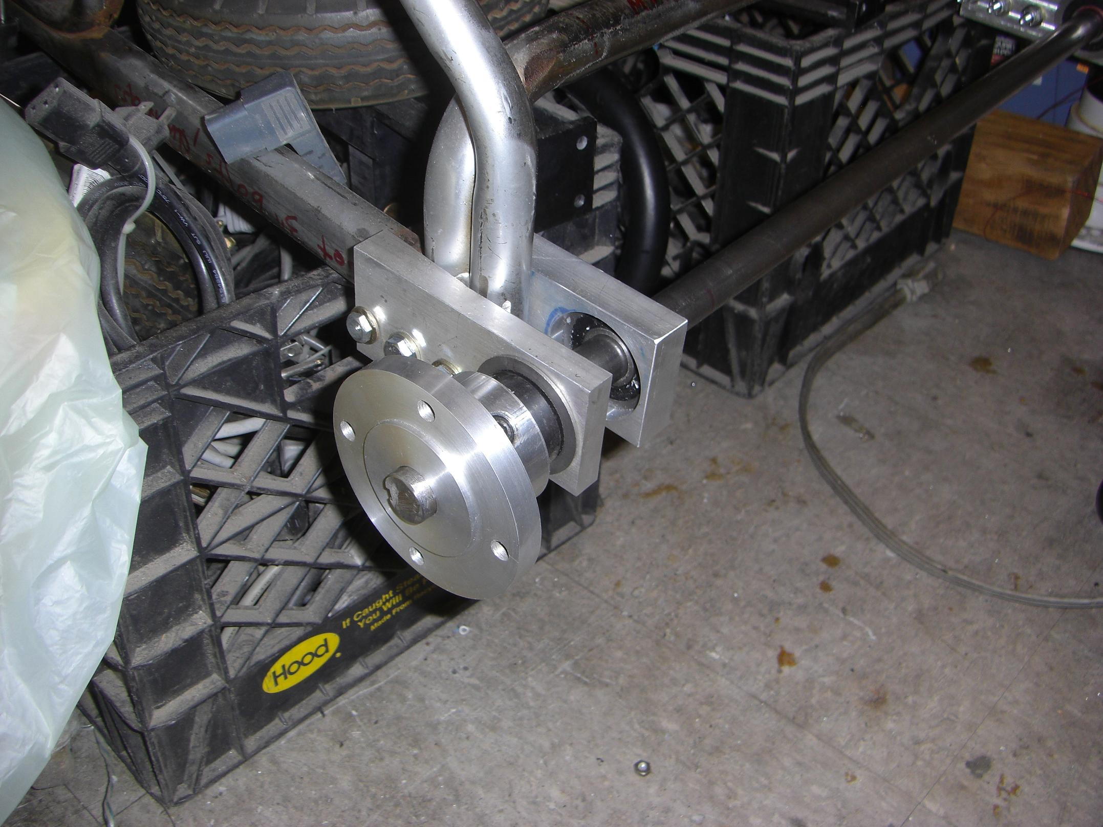
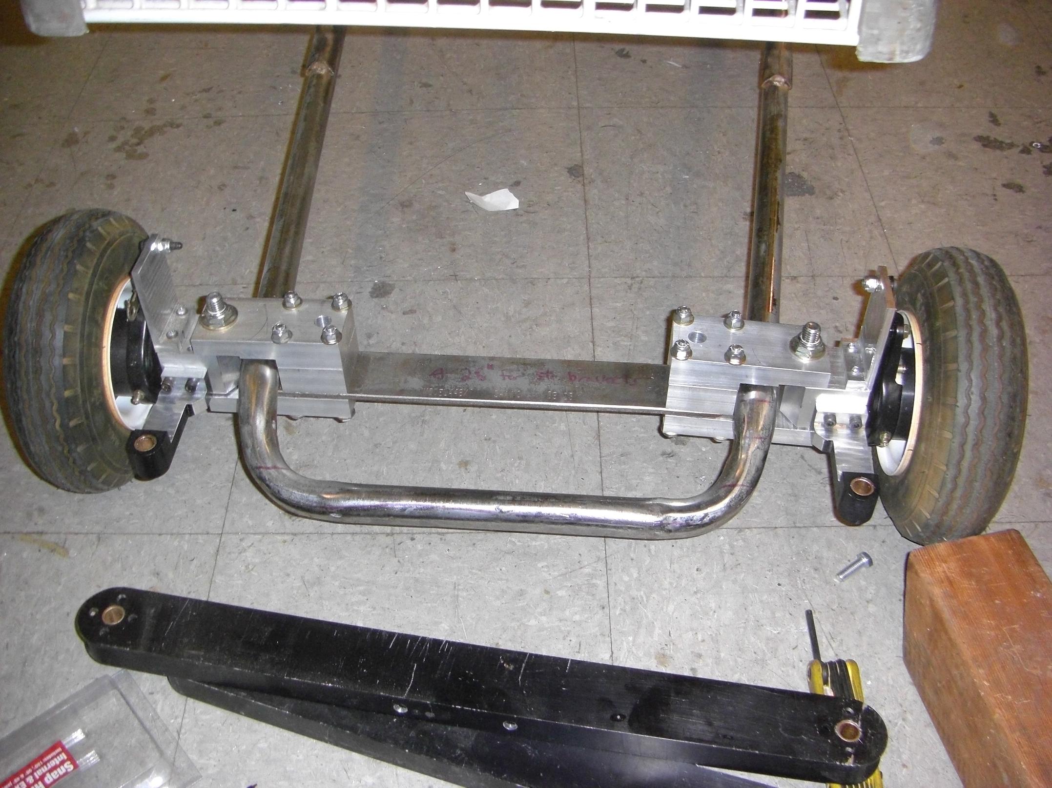
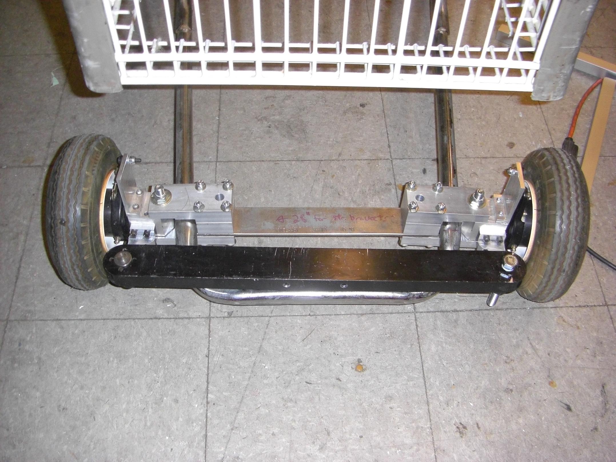
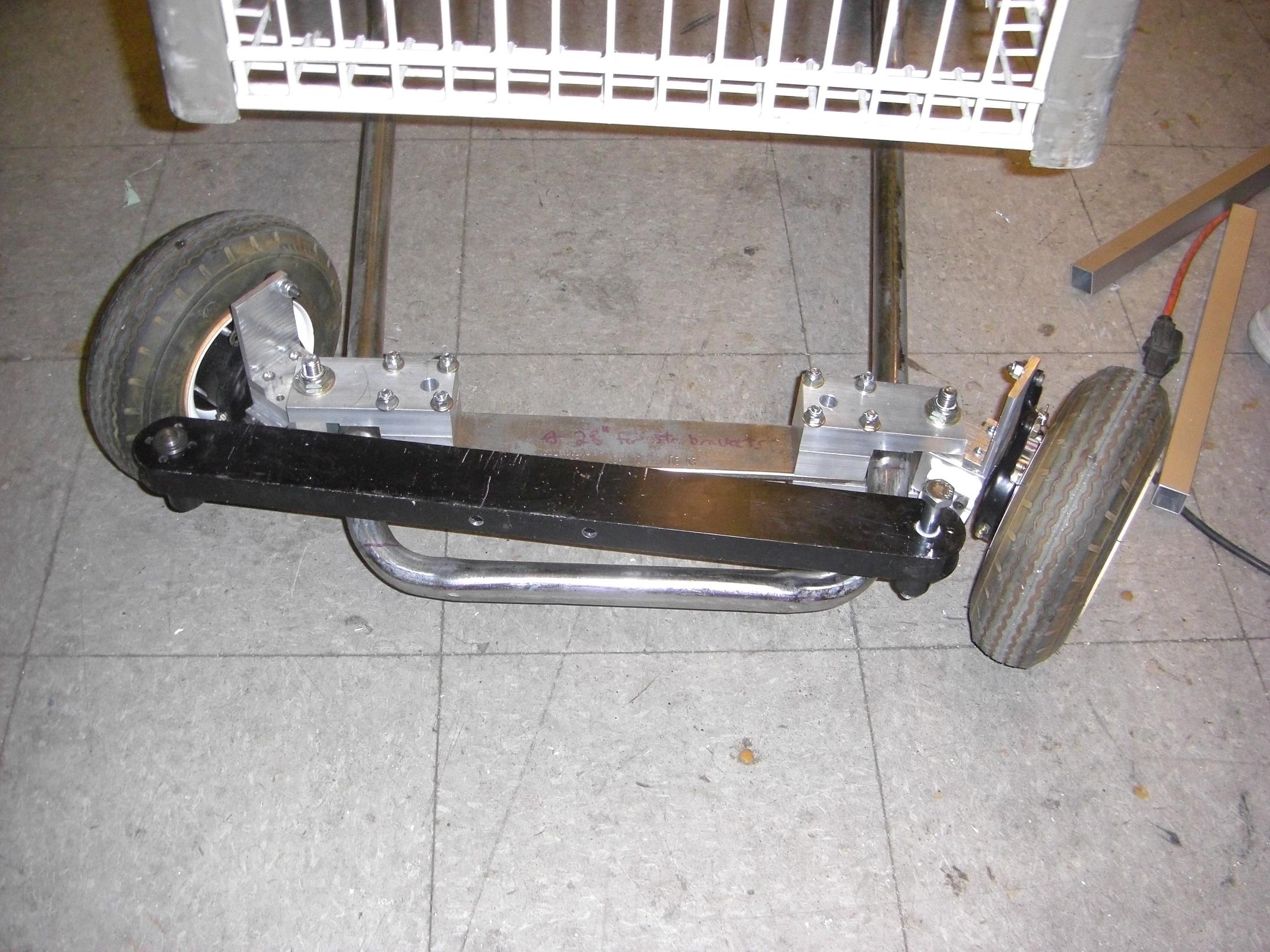
The business end. The relevant power transmission implement – there is only 1 – is housed completely in the rear wheel. It is a 80mm diameter custom-built 3-phase brushless DC motor, conveniently hidden within the confines of a 125mm scooter wheel. Maximum power on it is probably about 1000 watts. I have yet to properly meter it.

Even with no torque advantage (as a direct drive motor), the acceleration is pretty absurd. It’s not quite the neck-snapping and rider-launching takeoff of Snuffles 1, but I do need to hang on pretty hard. It is, however, a controllable launch, and will be even more so when a proper spring-loaded thumb throttle is installed (you know, so I don’t have to hang on with one hand and one leg while twiddling a knob on a stick with the other hand)

The whole vehicle is very low profile. Yes, I managed to drop the height of a Razor scooter – with an add-on battery pack. You think pebbles were bad before…

This is the “larger” flavor from Razor, which has 125mm wheels. With the belly pack, I still have about 1.5 inches of clearance. Not going to be bounding over any curbs or potholes, but it’s enough to get around on bike lanes and sidewalks.

There are four 4.2AH lithium polymer flat cells inside, and four outside. They are run in series for 29.6 volts nominal. The packs are rated for 20C discharge (80 amps) and can burst 30C, so I have plenty of reserve battery power. As for capacity, calculation showed that my optimal range at constant power on flat, frictionless ground in a universe with a constant gravitational field at a constant temperature in air with zero viscosity and me approximated as a point mass… is about 4 miles, no entropy generated. Realistically I expect far less, and need to do a real rangecheck some time soon. Anything above 2 miles is really enough to putz me around campus and into town and back.

With an extension of the belly box, and some custom control electronics, I could conceivably hide all the control stuff inside the tube frame, and only have a throttle cable coming out.

Yeah… that’s about how it is.

And it weighs this much. With better mounting facilities, it should weigh around 12 pounds. That’s a hair under 6 kilograms for you people in metricworld.

Anyways, work will now continue on dressing up the control system. I’ve officially moved past the “90% Zone of Project-Related Self-Loathing” which occurs with everything I build – I would furiously build it to 90% of the way, then just get sick of it and forget about it for a while. Now that I know it works, I should be a little motivated to push it through.

(read: expect another update in 8 months)

I have kept a detailed build log of this project and its predecessor on this site.

Bot on??

LOLriokart Update 6: Criticality Edition

In nuclear physics, criticality is when a chain reaction becomes self-sustaining. In MITERS physics, criticality is when your project can actually support its own weight without being propped up by 2x4s. It’s only taken me six months to put 4 wheels back on the kart (which can now function as a shopping cart again!). The driveline mechanics and steering linkage are still not complete, but at the very least, it can be rolled around at will to clear space in the lab.  So, naturally, it’s picture update time.

After making a mirrored set of bearing blocks, it was time to test the axle alignment. Either my parts aren’t square with respect to the cart frame, or the cart frame is just not square at all, but it takes a bit of malletwork to push the axle through. I have to keep the retaining bolts pretty loose during axle service also.

I thought of a few workarounds like remaking the double blocks from one single block, or using self-aligning mounted bearings, but put it off to work on the rest of the parts.

Temporarily mounting a drive hub to test fits and clearances. As expected, I’d need a shaft collar on the outside of the bearings to keep the tires away from the mounting bolts in addition to the collars on the inside. I may end up making this one large shaft-block-spacer assembly to reduce partcount.

With the rear tires bolted on, it was time to drop the thing off the milk crates which have acted as a work stand. Here’s the first “on-the ground” test. Not much a test, since it had no steering linkage or drive components, but it was a good chance to test the rigidity of the entire system by jumping in the basket and rocking around. Verdict: I approve.

Let’s get to work on the steering linkages. Out of the same mysterious machine that supplied my brake-o-hub original material come these trunion-like things. Each one is a one-piece machined aluminum block with a bronze bushing in it. How convenient – they seem like just the thing to turn into steering arms.

The left part is the original part, and the right the finished steering arm. I had to cut down much of the material to get to that stage, but it was the most compatible with the months-old steering knuckle design, and also an excuse to make the space smell like Tap Magic.

Test mounting the finished part. The chamfer allows a farther range of motion in that direction. Normally, the edges of the knuckle blocks themselves act as the hard travel limiters.

The combination of hard machined lines and angles give the front end a rather distinct look that I rather like.

So remember how the bearing blocks weren’t exactly square with the frame? They actually not square with themselves either. Small variations in how the steel tubing cart frame was welded made aligning the bearings to pass the shaft through extremely difficult.   To alleviate this, I made an inter-block spacer with pilot circles that snugly fit the bearing bores. At the very least, this forces the bearings to be square with eachother. The two sides may still be out of square, but retaining bolt holes can be fiddled with.

After properly spacing out both sides, it was much easier to remove and install the driveshaft. Speaking of which, I milled double flats on the ends to give the hub screws something to bite onto. The shaft is also internally threaded on both ends, so I can at least have something physical interlock (like a bolt with washer) between set screws and certain death.

With both linkage arms made, it was time to try and link them together to check out the steering geometry. The spirit of the mysterious machine supplied these dual-bushing aluminum spars which, by some chance alignment of Cybertron and Earth, was the exact length to provide perfect straight-ahead wheel alignment (Any toe angle is too small for me to notice).

And so the first inaugural test run of the kart was completed, with three people involved : One to ride, one to push, and one to flick the steering.

Steering linkage in (mostly) straight-ahead position.

….and at maximum departure from center, turning right. Notice the difference in angle of the wheels – this is an attempted implementation of the Ackermann steering geometry, which is what modern car-type steering is derived from. That’s the reason I took the extra step to make the steering arms offset to one side.

So that’s all for now. Even though the big aluminum link was fun, it will probably be replaced with some big tie rods to allow for fine adjustment. I have not planned out how to actually attach the steering wheel to this linkage yet, nor have I designed the motor mounts or rear powertrain. Or anything for that matter – the entire kart build so far has been design-and-build on-the-fly. I don’t know what parts I’m making until 5 minutes before I actually make them.

The primary goal is to get the steering and front brake system working, since that allows the kart to be used as a rolling chassis for any number of different propulsion methods.