Make-A-RaZeR

No, I didn’t just 3d-print a whole scooter. But here’s a quick review of the past several days’ work on both rEVolution and Make-A-Bot.

razEr rEVolution

First off, I finally figured out what the hell was causing all my Hall sensors to blank once every turn of the motor. Originally, I had suspected a spurious short caused by some exposed connection on the 5 volt Hall sensor power lines rubbing the aluminum can, or something in that same genus.  However, cross-checking the sensor current draw on a power supply showed that the blanking was actually caused by them losing power.

Uh oh. I pulled the motor apart, and as it turned out, the Hall sensor ground wire got mashed into the bearing when I dropped the stator into the can. It was technically severed, but the bearing closed the circuit so the sensors could be read anyway. At least, for 300 out of every 360 degrees or so.

That’s right. My motor was running its sensors through a bearing. Well that would explain its choppiness and propensity to sound like a moped with a badly tuned engine.

A quick reroute of the ground wire fixed all of that, and here’s a test spin of the Dual (non-)Interleaved RazErMotor using a small Kelly controller.

Yeah, so it sounds as rocky and off-center as most of my other hub motors. Blame my lack of patience in actually assembling the motor components. Otherwise, it’s also mounted solidly to a very hollow and lightly damped tube, which just makes it sound several times worse.

With the windings run in parallel (grouped as shown in the video), the motor came awfully close to scoring a perfect 1337 RPM at 40 volts, measured via LAZERTACH.

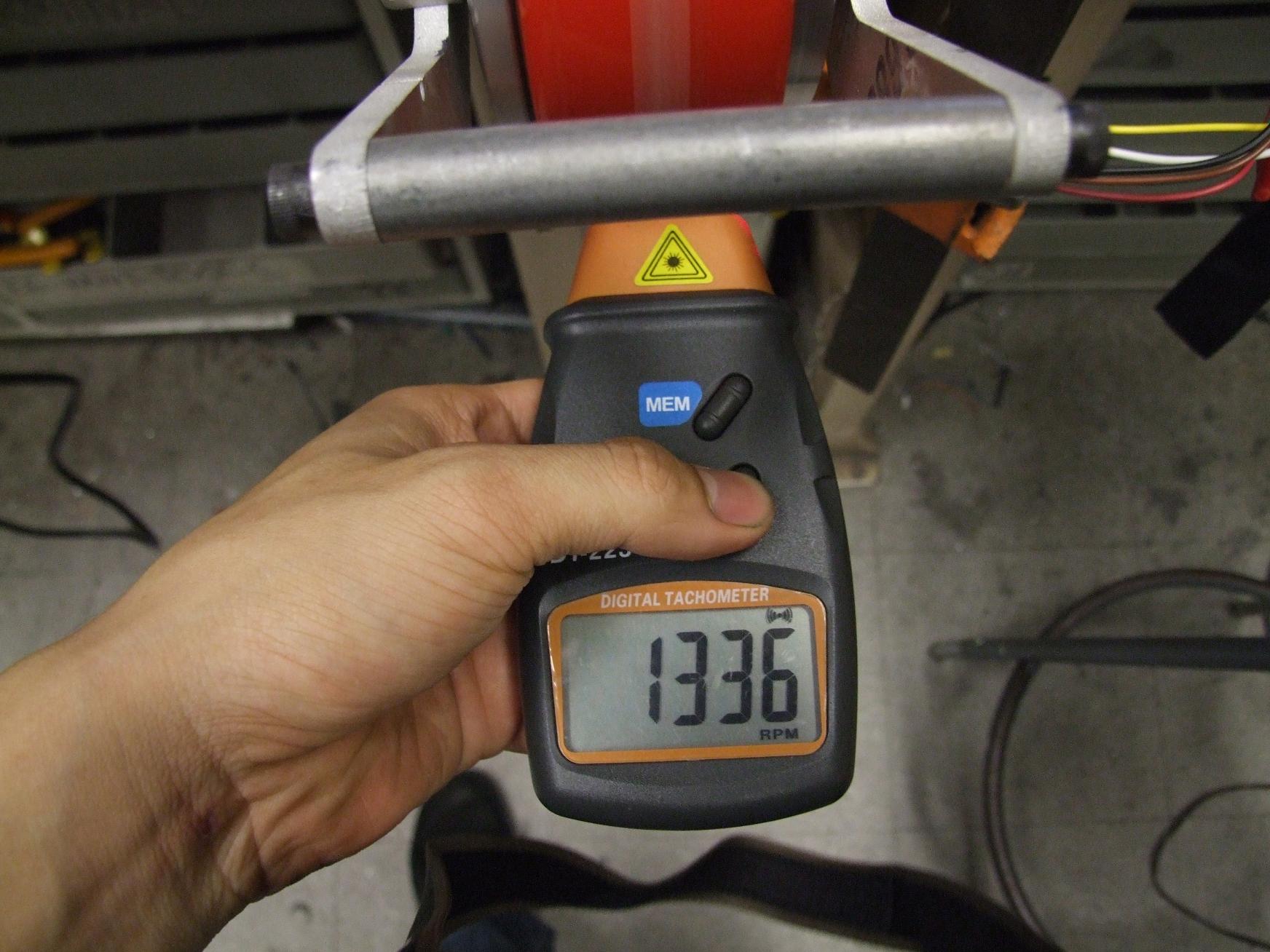
If only the battery had been a few millivolts higher.

Anyways, this translates into a “Kv” of only about 33 RPM/V, or 0.285 Nm/A in SI-world. I made an original prediction of 0.66 Nm/A in series connection (if the two half-motors were run as a regular dLRK type motor). In the parallel configuration, that number would be about 0.33 – which 0.285 is close enough to, since my prediction used the most generalized, ideal definition possible.

Next steps for RazEr include finally assembling the DEC carrier boards and then… well, making them carry DECs. Hopefully hotwired ones. As I discovered on the Citycar model, the DECs perform cycle-by-cycle current limiting, which effectively means the peak amps rating is not an average DC value – rather, it’s the amount of current it will try to clamp the motor phases to, period. This was a troublesome discovery for the CityCar model, and unfortunately could have been prevented if I had thought about what current limiting actually means.

I’ll have to see if the roughly 0.6 ohm resistance of each half-motor means that the most I can ever push into them is about 12 volts (I * R, or 20 amps * 0.6 ohms) – past which the DECs will just clamp. Now, of course, there is the option of just adding another current sense resistor to quadruple the original 10A limit… but that’s territory which can easily lose me an entire module in a split second if I’m not careful.

So who knows – maybe this is an opportunity to finally design the Melontroller.

make-a-bot

No, I haven’t waterjetted it yet. Quit asking.

All the work on Make-a-bot so far has been in the CAD domain. I’m slowly filling out the basic geometric sketch presented last time with T-nuts and … you know, actual components.

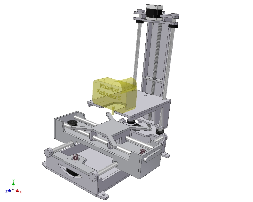
I’ve added some more solid material to the Z-axis column. In retrospect, the original column idea was quick and easy, but I had qualms about its stability… as well as the fact that I designed it at like 5 in the morning. Things which I design during those hours almost never turn out right.  Conceptually it’s sound, but solid mechanics will probably tell me otherwise once I build it.

As a result, I’ve added the Giant Aluminum Tower around the existing guide rod and motor mount.  The GAT will be put in compression from the top using the threaded rod, and the guide rods will not be structural any more. At least, this arrangement should be more stable than the original plan.

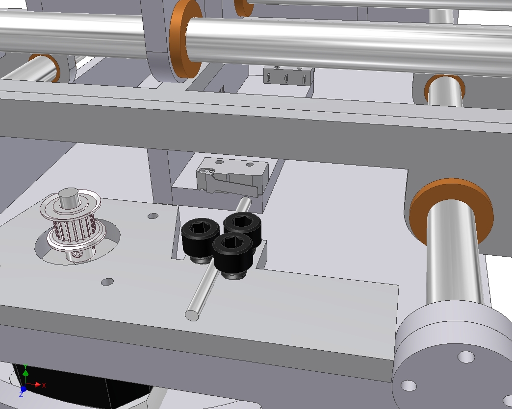
So now with the geometric structure complete, I can start filling in the details. Check out this Cleverly Engineered System for attaching the Y-axis limit switches!

I decided to keep a “flying limit switch” setup i.e. keeping them on the carriage instead of on the machine base because the front and back sides of the base are decidedly asymmetric – I wanted to keep the number of part variations down. Plus, I was going to need a wiring harness for the traveling Y-axis anyway.

The added bonus is that because the endstops have been reduced to a hardware problem, they can be adjustable. So, those three screws on the motor mount let me slide the rod in and out to engage the switch at whatever distance i feel like is appropriate at the moment.

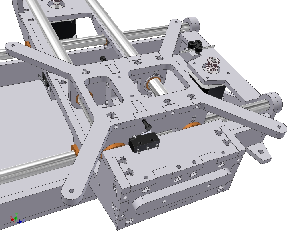
Taking a page from my engineering books, I’ve decided to put one half of each axis on flexure mounts. Each of those pull-tab-like rings is the new bushing mount for its quadrant. Therefore, the bushing is allowed to flex side to side very slightly to accomodate for misalignments in the guide rods.

In short, 3 points of contact fully define two objects with respect to each other. Adding a fourth is redundant, and unless they are all in the same plane, will cause problems. For a machine axis, this means binding, and that’s why many linear guide systems have only three bearings, or have adjustable ones.

Assuming I did this right, the bushing should be allowed to float side-to-side (i.e. in the direction of X for the picture shown) on the order of only a few thousandth of an inch or less. The flexure, being very short, will still support some of the vertical loads (in the direction of Z) of the whole system. Because only this side of the Y axis is flexure-mounted, there will not be slop in the X direction because of the fully constrained bushings on the other side.

If I did it right.

So now I’m starting to add the intricate T-nut work to the frame. These T-nuts are a departure from my usual style (flat bottom) and are more representative on what’s found on most other 2D-fabbed works in Makerdom.

The reason is that flat-bottomed T-nuts are very sensitive to hardware length tolerance. There’s nowhere for the screw to go if it is slightly longer than the design length, and it will just dig down into the material and defeat the purpose of having the nut there – if the nut is just pushing back on the material, that fastening location does not provide any fastening force.

The cruciform T-nut (Crüx-nuts? Jesus nuts?) allows for variations in screw length by letting the screw poke out past the nut. Now, I’ve never found my screws to be more than .01″ or so apart, but I’ve accomodated for up to 0.55 inch actual screw length on 0.5″ hardware here.

There’s also another Clever Limit Switch setup on the ends of the Y-axis carriage. Again, adjustable by turning the little cap screw that ultimately gets faceplanted into the limit switch.

Notice the X-axis carriage also having flexure mounted bushings.

For kicks, I dropped Cold Arbor’s assembly model in side by side. This machine is going to be pretty chunky. For reference, CA is 20 inches across the curved diameter and about a foot tall at the upper edge of the saw.

It’s definitely bigger than a Cupcake. So what’s the next size up, a muffin?

Maybe I should look into stronger stepper motors…

RazEr rEVolution: End Menial Labor

When we last left rEVolution, I was halfway through the process of turning my hands into bloody, tattered stumps. It’s a ritual that occurs with the construction of every hub motor (which means I went through it four times to make the RazErBlades).

And by all that I mean winding the motor. Here’s the end result, terminated for presentation.

I ended up keeping the “split dLRK” winding style – making 6 teeth wound AabBCc and the other 6 aABbcC.  They’re terminated in separate non-connected star points on the underside. The leads are grouped by their respective phases – motor 1 is the classic white-red-black, and motor 2 gets yellow-green-brown.

My patience deterioration is very clearly shown in the picture. I wound this motor starting from the Aa side and proceeded counterclockwise. You can see a decay in the quality of windings and the neatness of layers right after the aA phase on the left. Then by the last one, it’s all gone to hell.

To maintain engineering rigor, I took measurements of the DC resistance of each phase. This will pretty much determine how much current the motor can ever pull.

I proceeded to defenestrate engineering rigor (MITERS has very large ceiling-height windows, so this was easy) by scribbling the resistances hastily on the workbench. In dry-erase.

From the picture, you can deduce that the C phase of motor #2 is about 10% short of turns. Yeah, I think I pretty much stopped caring by that point. The other phases should have 39 to 42 TPT, but I’m guessing 35 or less made it onto the last C phase if I’m lucky.

Fit test!

I tried giving the motor a test spin using a sensorless controller (essentially by bootstrapping off Melon-scooter), but neither half-motor exited the “starting” regime. This was concerning. Did I terminate them wrong? Wind something backwards just a little bit?

A few minutes of diagnosis revealed that the motor was technically running smoothly, but the controller just didn’t increase throttle. Applying voltage to each half-motor in each combination of the 3 leads (i.e. A to B, A to C, B to C…) produced 6 identically spaced angular positions each time – which is indicative of correct winding, since that’s pretty much what your controller does anyway, just alot faster and without colliding alligator clips.

I pretty much just declared it to be a fault of shitty sensorless aircraft controllers being unable to deal with inertial loads or high friction systems.

Without a supply of hall sensors, I put the frame and motor away and started thinking about the other parts of the electrical system.

EVs generally have 3 big components – motor, controller, and battery. With the latter two, you can shoehorn anything in as a motor. With motor and battery, you can be a dumbass like me and control the vehicle with a mildly more civilized form of touching 2 wires together. But without a battery, what am I to do – run the whole thing from a bag of lemons?

Luckily for me, people have figured out how to stuff the equivalent of tanker-loads of lemons into lithium nanophosphate cells. Above is the 12S2P A123 DeWalt 36v Lithium pack during mid-assembly.

I managed to find some terrifyingly wide copper braid this time, and I think the cells just look so much better with them instead of the \m/etalpaxxx‘ quadruple braid. The massive interconnects just scream this pack will dump enough amps to destroy you and everything you ever loved.

Another serving of giga-braid later and the pack structure is complete. I decided to split the pack into 2 6S packs again for balancing purposes, but this time the pack isn’t two separate entities. Shane supplied me with Real Legit JST-XH Connectors of Battery Balancing (+14, for pin count), or otherwise I would have probably resorted to 7 pin-header again.

Bottleshrink returns once again, but this pack is so long that I needed the midsections of 3 bottles to completely enclose it. Luckily, it fit 2 liter bottles fine, and I just pulled a few out of the recycling bin.

A quick check of the cell levels revealed that these cells are in fact still quite healthy despite sitting for an unknown period of time.

Of course, that all went to hell on the first charge, and I had to spend an hour manually bringing each cell group up to full.

back to motters

Given that the motor itself seems to be correctly wound, I surmised that all my problems would go away as soon as I added the requisite hall sensors to the slots.

And here they are, temporarily CA’d in place as a soldering fixture. LRK-style motors need a physical 120 degree sensor arrangement, but I’ve always found cross-stator wiring work to be awkward. Therefore, like on the skatemotors, I take the B sensor and flip it around for a 60 degree, every-two-slots layout.

I secured a chunk of 6 pin cable to the access slot in the shaft using epoxy. At the same time, I elected to secure the phase leads to the other side of the motor. The whole epoxy-globbed mess was then introduced to my epoxy curing oven fixture implement hair dryer hanging by its power cord from the ceiling.

After the first round of epoxy set, I finished connecting the sensor wires. Unfortunately, I managed to break off the output pin of the B sensor… and so ended up having to install the opposite one anyway.

Luckily, this design left plenty of space near the edge of the stator, so running the wiring all the way around the motor wasn’t as difficult.

The sensors got their own layer of goop. I kept finding buckets of different epoxy fillers around MITERS – this is “cellulose” filler, which probably just means paper dust.

It claimed to be less cancer-inducing than either the silica or phenolic microspheres, so I gave it a shot.

After another hour or two of watching glue dry, I put the motor together. Here it is – Dual (Non-)Interleaved RazErMotor!

But does it work?

That’s a gooooooooood question.

Using the Kelly KBS which sort of miserably failed at running Melon-scooter, I was able to briefly power up and spin the DNIR to full speed. Qualitative observation tells me that at least I didn’t get it that wrong. The fact that it moved at all meant that I got the sensor arrangement correct for the “split dLRK”. Now, for this test, I just paralleled the equivalent phases of each half-motor. Once I put together the RazerDEC board, each motor will be powered by its own controller, but triggered from the same sensors.

The speed was visually in the “correct” range and it started and ran smoothly with no signs of improper winding or termination.

that is, until it started sounding like a moped.

Oscilloscope diagnosis of the sensor outputs showed that every mechanical revolution, all 3 sensors were blanking. This caused confusion for the controller for a split second until the sensors outputted a valid signal again.

Well, this is disappointing. The sensors – which, mind you, I had JUST encased permanently in a cellulose-epoxy matrix – seem to be having power issues once per mechanical revolution. I’m fairly certain it’s power, anyway, because there is no physical way for all 3 sensors to read the same field orientation the way they are set up.

This actually means it shouldn’t be hard to fix – my guess is that somewhere, a bare solder joint is nicking the metal can once per revolution and causing a short between sensor 5 volts and ground. A further test to confirm (or dispel) this would be to look for dips in the 5 volt line during each revolution.

In the mean time, there’s no pics of it running, therefore it didn’t happen.