Überclocker 5: Finishing Up The Everything Else

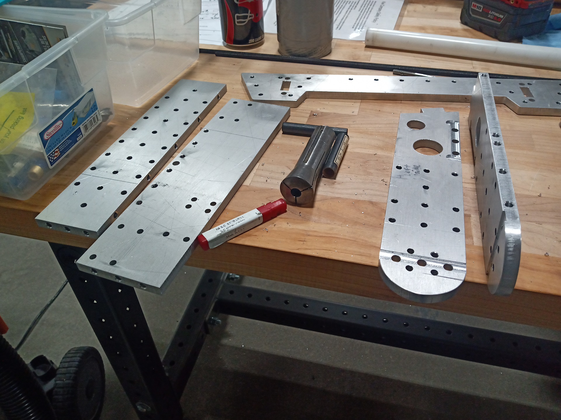
Last episode, I had just finished machining and assembling the frame. As I said then, it felt a little wrong. Almost too simple compared to my usual. Well given that’s one of the major directives of this build, and for Overhaul 3, I’d better get used to the feeling. So with the aluminum machining taken care of, it was time to do some welding and final assembly.

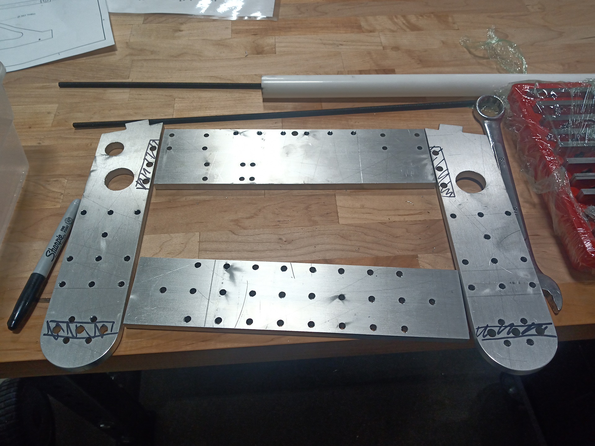
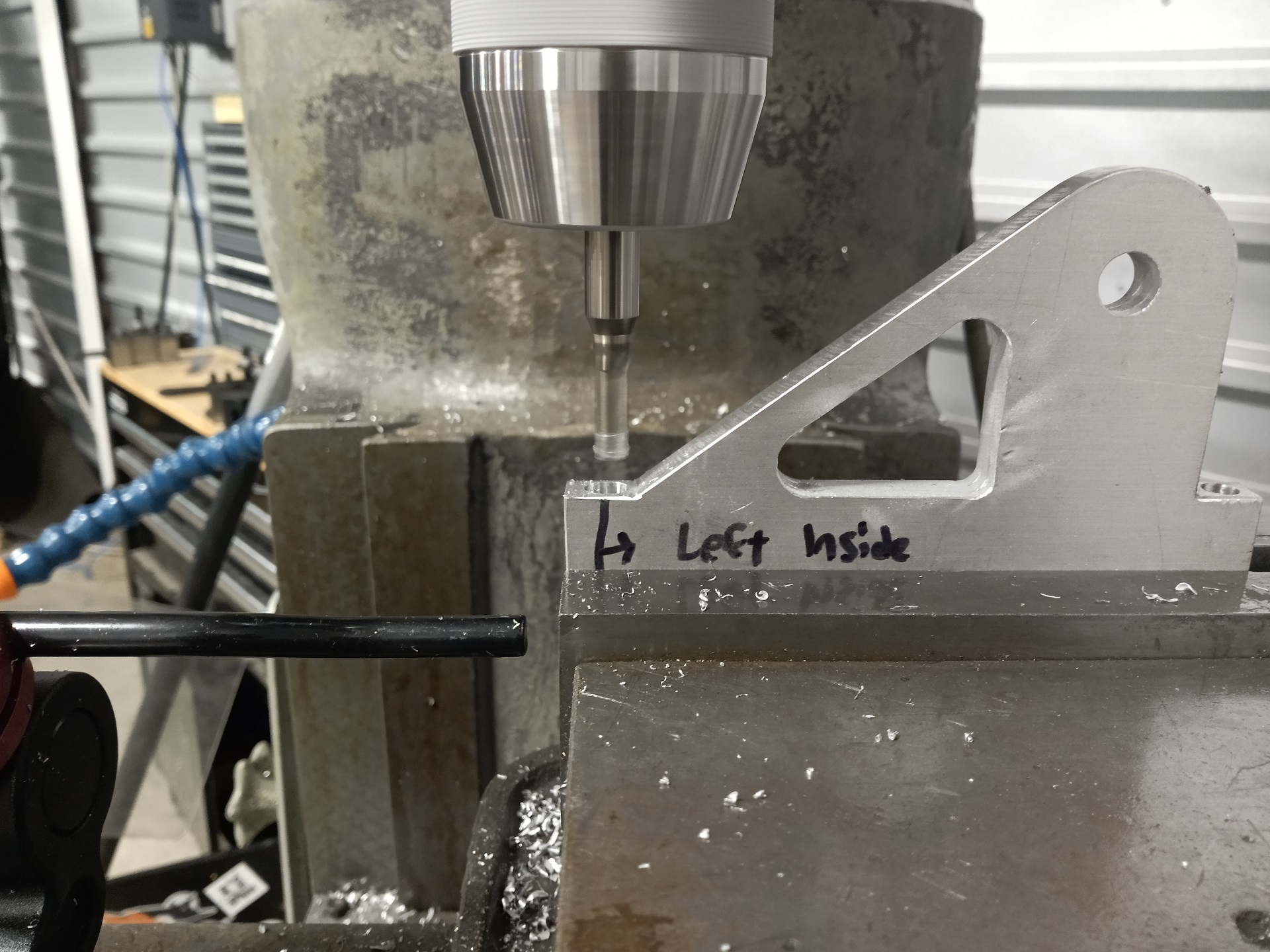
The new leg design is almost 1 for 1 what I want to build for Overhaul. Its armored pontoons were a good idea for some forms of kinetic energy weapon dispersal, but weren’t very good at wedging otherwise. Last season I made the “stiletto” versions for matches where having broad surfaces against the ground would be a liability, but the way it mounted to the bot was still predicated by the angled wubbies. I could adjust their ‘preload’ into the floor with washers, but this was permanent (for the match duration) and they actually would impede the bot’s motion by slightly lifting the front small wheels off the ground. There’s really no substitute for a good set of hinged wedges that will always conform to the floor under gravity. I’d eventually want to redo these plates from an alloy steel like Hardox or good ol’ AR400, but for now, a surplus piece of on-hand 1/8″ cold roll steel works too.

Initial tack welds were laid down the parts as-fixtured, then I’d remove the leg itself and add a dab more weld bead. The design was specified for approximately 4mm gauge AR steel, but using 1/8″ cold roll meant there was a lot of placement slop, so I’d rather fixture as the parts were going to be used.

Top side in progress, mostly done.

And then backfilled from the underside. I then ground all four undersides smooth, and painted over the legs and mounts in black.

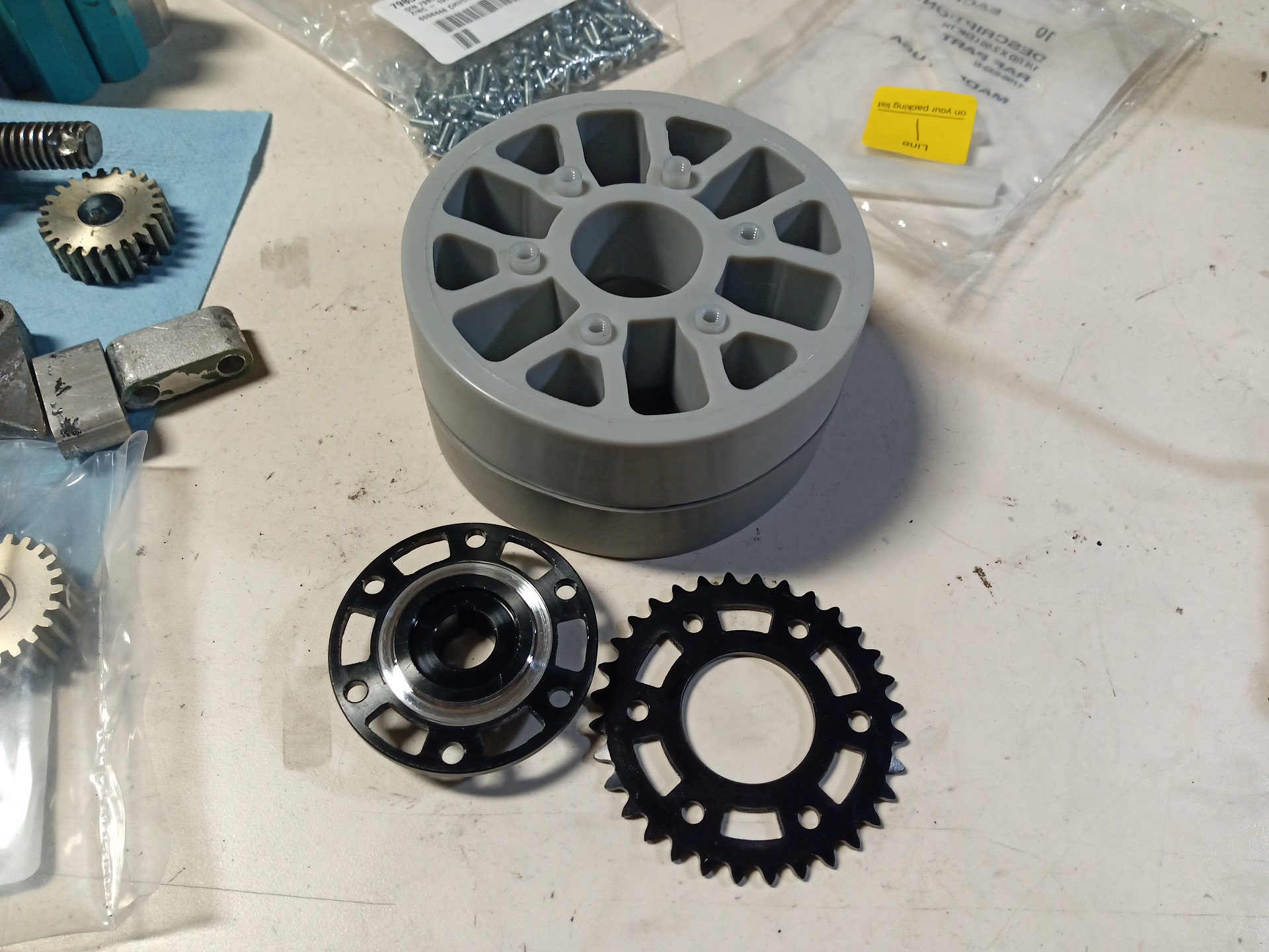
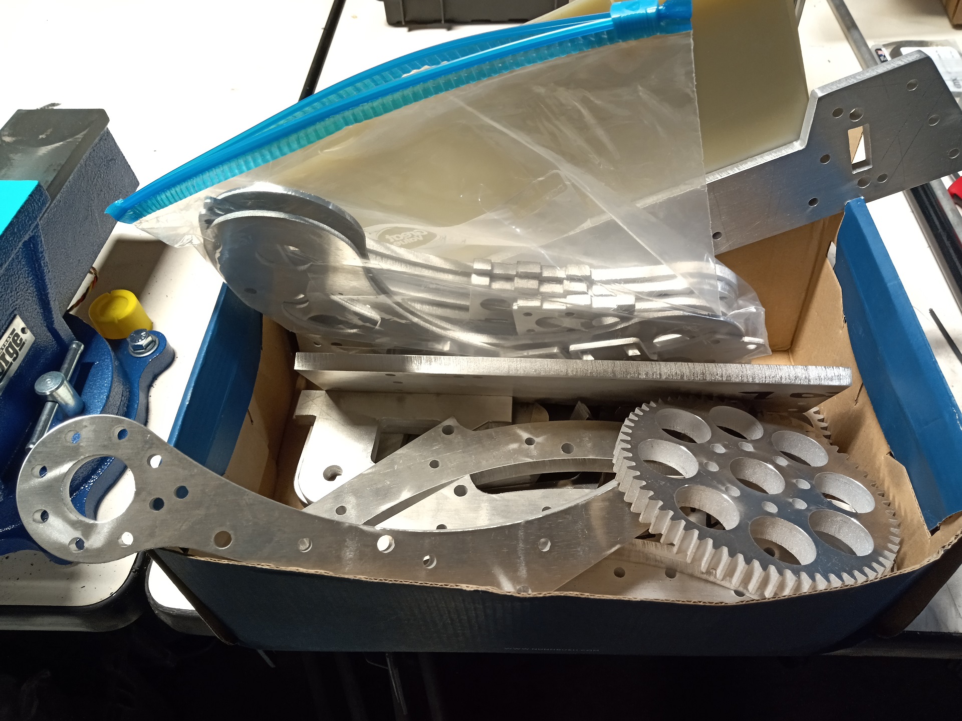
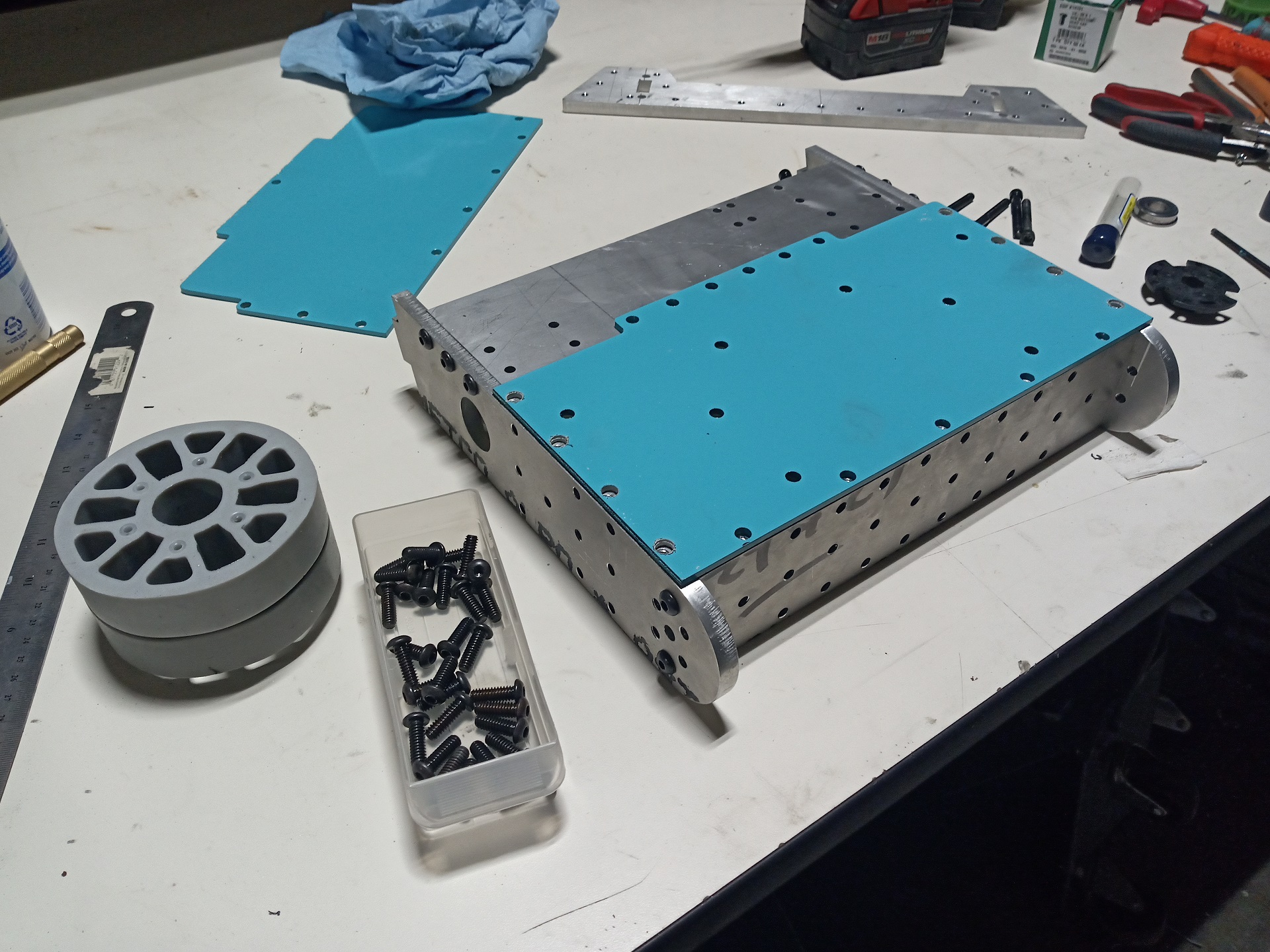
While the various painted parts are all drying, onto assembly work.  There’s a series of little spacers that have to be installed for the wheels to attach at the right distance to clear the drive chains. Not the most elegant approach, perhaps, but one that was workable given the commercial nature of the parts. For Overhaul I’d have custom hubs with the correct spacing already designed in.

On the inside, a series of washers to hold the hub face on. Another slight point of tack is to put the wheels on, you really need to remove the outer “hubcap” plastic Versahub because otherwise there’s no easy way to line everything up looking through the 1/2″ hex bore. A minor complaint, and really I could just put a plastic circle piece here instead of the Versahub.

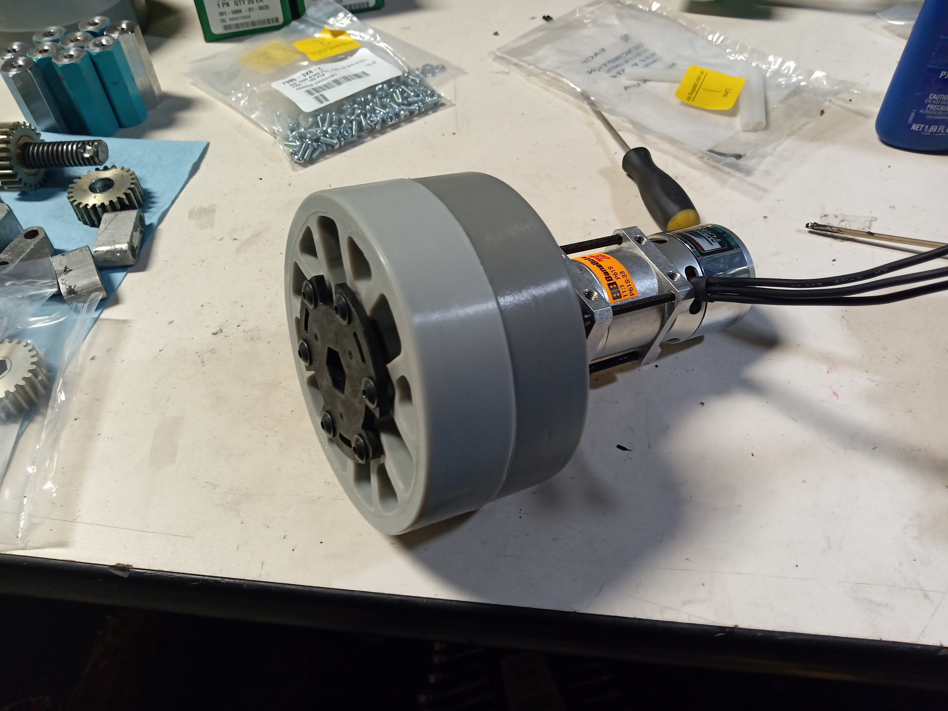
Well, it has wheels now!

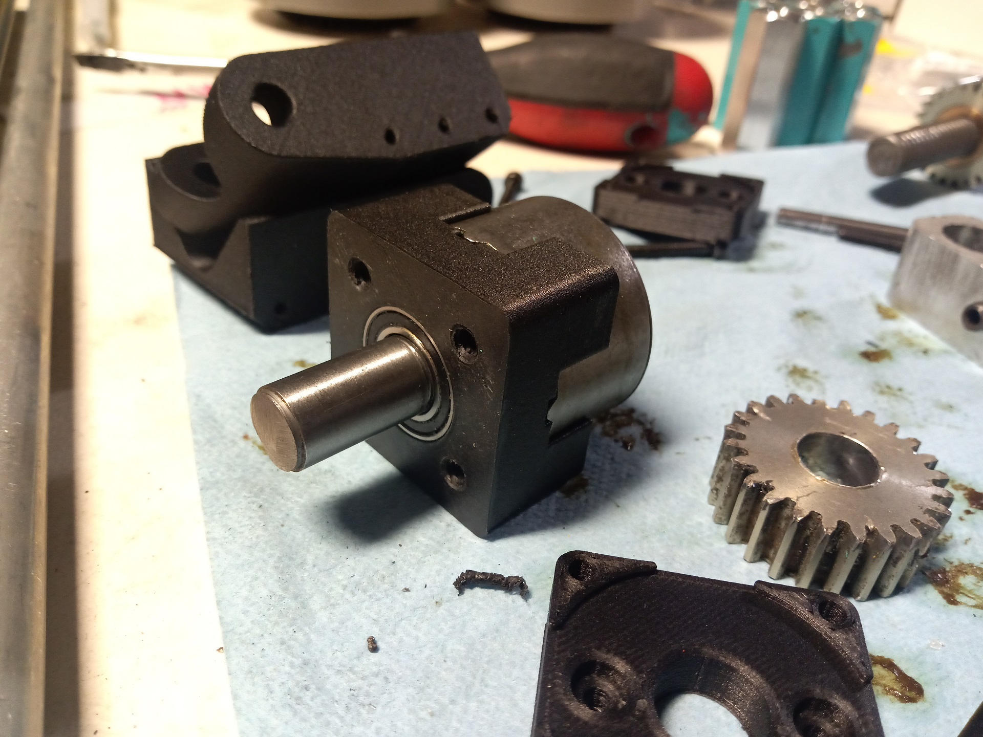
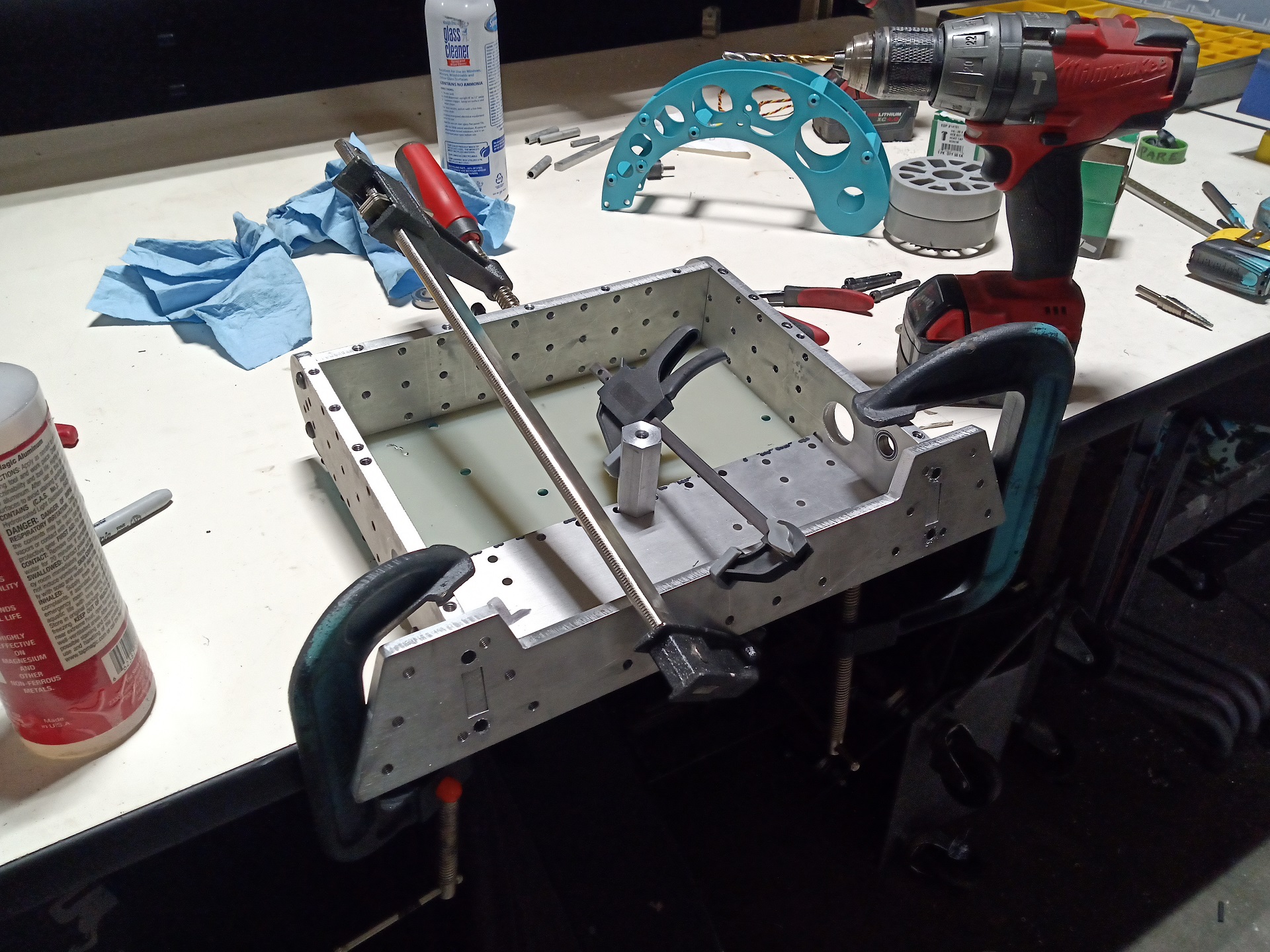
The lifter motor is suspended off the lower plate by a large gearbox-shaped spacer. It’s a bit of an overconstraint with a fixed bearing in the frame rail; same with the external bearings on the drive motors. Overhaul will have these be isolated systems with flexible couplings like I have on the existing lifter design.


The lifter fork and clamp parts all slide onto the main shaft one by one. The dead shaft does allow this thing to be far more serviceable than Clockers Past.

Once the three crossing tie rods and spacers are tightened, the assembly is rock solid. Unlike Clockers Past, the only method of force transmission  from the lift gear side to the “drive” side (right hand) is through those three interspersed tie rods. With the live drive shaft, both forks directly received motor torque. Now, My Calculations Show™ that the rigidity is adequate even picking up a 30lb opponent entirely on the right fork.

Overhaul already has a method of through-transmitting lift motor torque in the form of the big hollow hub the arms sit on, so the considerations there are much different.

Support legs all installed and tightened. A shoulder screw whose shoulder is the length between the hinge sides gets tightened down, and that’s all.

As I expected, this thing is really front heavy. The CAD model doesn’t quiet show it all, even, because it’s a static representation. With nothing in the back, the bot tips forward on its two front wheels immediately.

There will be things in the back, of course, and the final design showed I could possibly have a 3 pound counterweight spanning the back frame rail.  We’ll see how it ends up. I also suspected that the bot will drive very differently depending on how squished the front wheels are (i.e. how much downforce is placed on the arms).

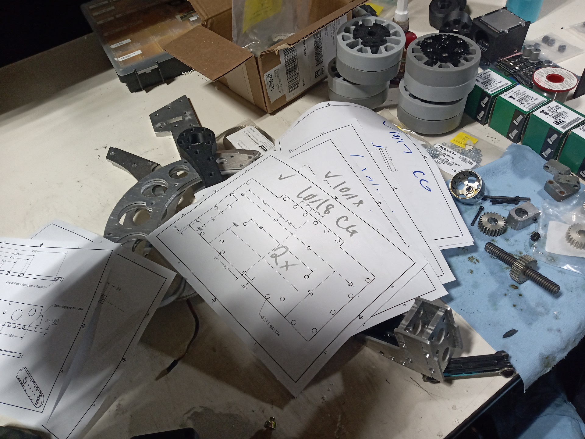
One minor “oh yeah, I modeled that” as I mounted the drive chains: I specified flat-head screws for most of these frame connections, but to do waterjet layout when I wasn’t the one using the machine, I had to make a configuration of each part with the countersink diameters suppressed.

Then I promptly forgot I was supposed to use flathead screws, so installed button heads. This works fine for every place that doesn’t have a chain run next to it, of course, so I didn’t even notice until now.

Ah, that’s much better.

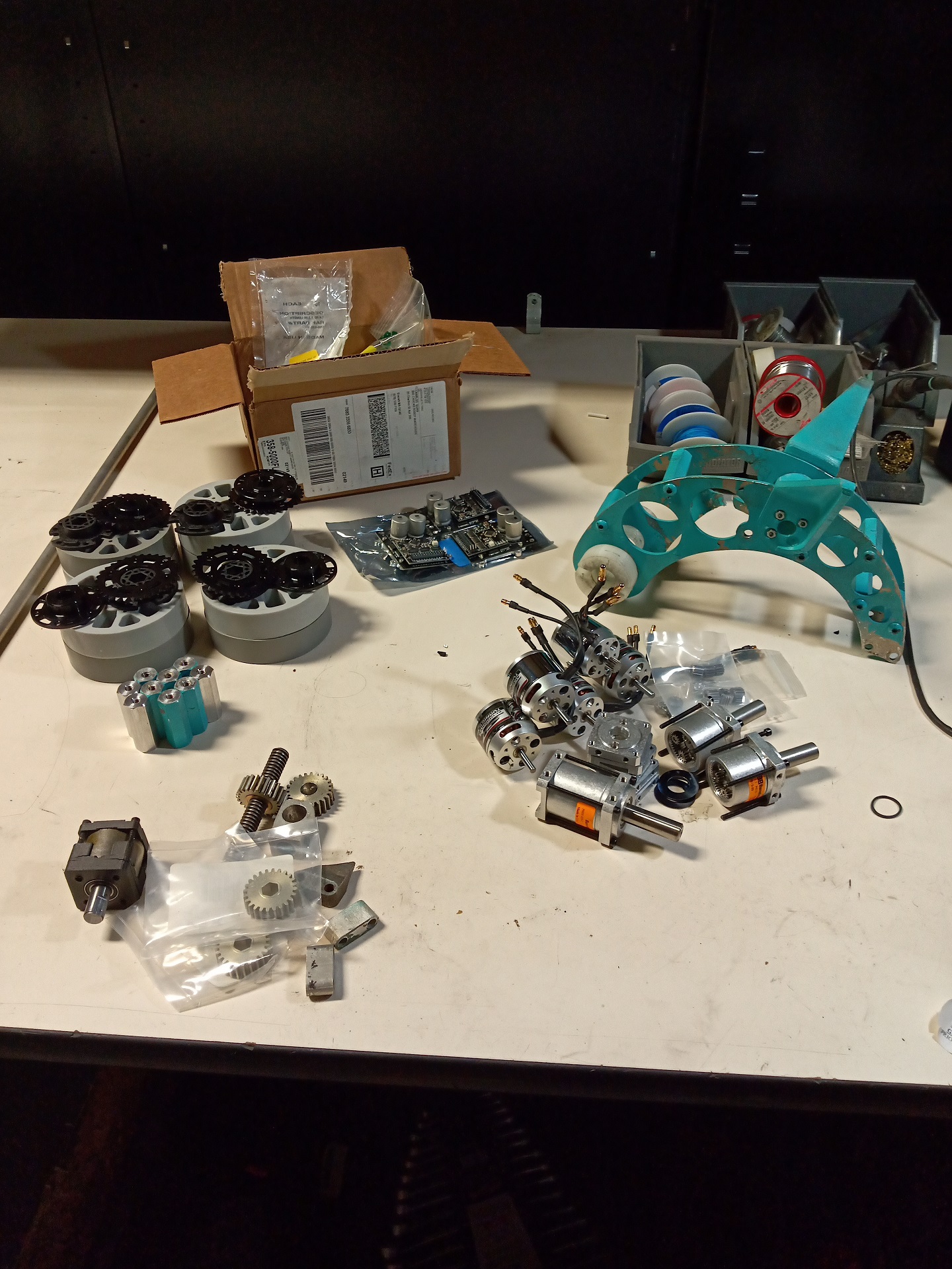
Electronics installation goes quickly, but first, I needed to throw things inside to get wire run distances.

Another “PM Charles” habit I learned and now don’t feel right without: I even created a wiring diagram for this thing with gauges, connections, and lengths before I cut a single piece of sumptuous silicone-insulated ultra-flexible noodle wire. And labeled every cable as I made them.

(As wires get into the multiple-0 gauge, they and their connectors begin getting more and more sumptuous as well as expensive if you fuck it up)

I avoided making something intelligent like Super DEANSBUS and instead just went for the good ol’ Hong Kong Soldered-Shrunken Squid. I only needed four ESCs and an auxiliary connection (for receiver power).

Prepped and ready after a couple more hours of soldering. I’m very much now used to crimp tooling and contact systems used in commercial/industrial connectors. The R/C world really needs a “crimpable bullet connector” of some sort (And I don’t mean these trash-tier things), because solder cup filling for dozens of wires just takes so much manpower.

And here it is!

I was very much right when I said it would drive differently depending on if I had the arms down or up. If the arms are raised, the back two wheels basically aren’t there – it drives like a 2WD bot and is almost too squirrely. Overhaul 1 had similar issues, but the long triangular pontoons damped it a lot.

However, if I drop the arms down and preload them into the ground even a little, it will transfer some weight to the back wheels, unsquishing the front wheels just a little. It gains 4WD-like traction, but still puts substantial weight down on the forks. I actually managed to accidentally sand a good mount of the forks off on the bottom driving around in the rough concrete area of the shop.

This is a desired result. If I make sure Overhaul can sink down a good half inch or so in the front when the arms are raised, it means I have a fairly large band where the arms can be down and the bot still retain full traction. OH2.x wasn’t capable of this – the small wheels deformed so little that it propped the front 4 off the ground, making it act like a front-dragging 2WD bot.

On my mind now is a good way to make an easily adjustable travel limiter so I can, if need be, just slam the arms down without having to modulate them carefully. On this bot, if I drive them down too far, I can get it to start behaving like OH2.X – turns become more difficult and less predictable as the rear of the bot is trying to pivot around a drag point in the front.

The final weigh-in is pretty much on the money minus the weight of the wires, which I didn’t put in a simulated blob of copper for. The CAD weight was 26.7lb. Looks like either way I’ll have around that 3 pounds to play with to install a counterweight on the back plate!

Stay tuned for some exciting Orlando Maker Faire coverage, where I’ll get to find out if everything is wrong.

Überclocker 5.0: In Which I Actually Have to Build the Bot, Not Just Talk About It

Here, have an Überclocker kit. That’s it. My job is done and I’m going home.

Hah – funny story though. The past 3 generations of Uberclocker were actually ALL sold in the end to other builders. That’s right – before this build, I didn’t possess a single one of them. They were sold in various states of disrepair, of course. But sadly, I have yet to see any of them back in the arena, or face my own follies.

By the last week of September, this was the pile that I’d collected. The last head assembly is just for show – it was a spare made for the previous bot (Uberclocker 4.0) and is damaged in a couple of places. I’d gotten orders in for motors and pulled a couple of other Clocker 4.0 parts out of the organizer. A lot of this will see reuse intentionally.

Putting together a wheel assembly revealed that the Vex aluminum Versahub downloadable model is WRONG! It shows up as a flat face on the oberse, but in reality, has a shoulder that is larger than the 1.125″ on the other side. Vex uses 1-1/8″ as the standard because it also happens to be the outer diameter of a Type R8 or FR8 bearing, a very common bearing size.

So I had to turn the short shoulder down to 1.125″ in order for it to actually fit the plate sprocket. No biggie, but hey, update your damn CAD model.

Notice how the wheels are mated together – they have the previously mentioned #8-32 standoffs crammed into them. If I trusted friction enough, there isn’t even a need to have something on the other side. These were rather tough to press through!

One of the plastic Versahubs caps off the outside here. The whole assembly slips on to the P80 keyed shaft and is retained by the shaft’s end-tap screw hole and spacers.

That’s it. What? I made a drive system that’s one gearbox bolted to one wheel? On purpose? Boy, haven’t done that in a while.

The P61 gearboxes assemble almost directly onto the Sk3-4240 motors using the Mabuchi 775 motor mount kit. The shaft is too long by about 6mm however, so I had to trim all of them with a Dremel disc and cleaned up on the belt sander.

I printed off a couple more of these “Angerboxen” as I call them, which have been a staple of my bots for a few years. They’re based on a design I made all the way back in high school (with less tools) and carried through to bots like 12 O’Clocker, and then a spare motor from that made it into Uberclocker v4.

They’re just repackages of generic single speed drill gearboxes into a 1.5″ square profile, compared with their usual 2″ funny shapes. This will be the first time I cram a brushless motor into them, though. For the sake of convenience and expedience, it’s easier to keep this bot all brushless instead of make room for a brushed Ragebridge. Previously, Uberclocker 4.0 had a DeWut for the lift and a 550 size drill motor for the clamp, so it made sense.

I picked up a 4.95mm reamer to bore out some spare drill pinions (I have a 10 pound bag of loose random cordless drill guts) to turn them into pinions for the SK3 motors.

And here it is ready to close up!

…and a day later, after a quick redesign.


You see,  the SK3-42mm motors are bigger in diameter than a 550-size drill motor. Not by much, but by annoyingly enough that I could not feed one of the threaded tie screws in from the motor side.

I ended up changing the design up to have the tie rods enter from the front, basically making this an ersatz P60/61 gearbox. I mean, at this point there’s no real need to have a custom design and I might as well do an “embedded P61” like Overhaul had the P80 integrated into the clamp motor. But this setup is lighter and already designed in, and it was easy to replicate.

I added a set of 2 smaller holes in the center for a Mabuchi 400 size motor. This faceplate mount is often found in the smaller 28-30mm brushless motors – if weight got out of control, I could quickly drop the motor weight in half by going to one of them. I don’t need the full power of a 42mm brushless on the clamp arm anyway, but it was there and easy.

All of the subassemblies and components are starting to come together now. If there’s one thing that 1. Building Overhauls and 2. Doing Massive Drone Startups have taught me, it’s always just pipeline spares if you have the materials on hand. You will need them sooner or later, whether gust of wind or gust of Tombstone.

The lift arm shaft, unlike Clocker 4.0, is now a dead axle like Overhaul. I wanted to ensure the less complex box frame had more members to tie it together side to side. Pretty much every Clocker Past has had a live axle to let me easily turn a shaft collar into a torque clutch., but for this one I’m doing it dirty! Shown here are a bunch of spacers to keep the arm elements at the right distance apart. The shaft material is McMaster’s “ceramic coated aluminum” shaft material. Easy to machine, but you have to break the ceramic coating which is actually fairly tough. It will eat regular steel tools, but carbide will defeat it.

After the first week of October (Well, there goes Franklin Institute), my waterjet parts arrived from a local vendor. I dropped off material the week prior, so an average turnaround time, plus picked up a handful of company parts while I was at it.

This was enough parts for two bots except the frame, which I figured wasn’t going to get trashed at a Sportsman’s Class competition like Robot Ruckus, so I decided to not incur the extra cost and the having to order additional material.  I’ll do this for Motorama instead, where I plan to enter Clocker into the full combat 30s.

Checking off your own fabrication prints is always satisfying. Maybe just left-over project managment energy in me, but this is definitely my most documented and organized bot in years. Having other people needing to read your thoughts and intentions clearly in mission-critical systems is something I’ve had to get used to in the past 2-3 years, and I most definitely learned a ton from other folks at the company with more extensive industry experience.

(Not to say these are remotely version-trackable and custody-chain verified prints…)

I even back-added the “live edits” into the drawing files and annotated the CAD model. Oh, the horror.


Both Uberclocker and Overhaul make extensive use of these 12 pitch, 12 tooth, 20 degrees P/A stock spur gears. I made a point of just ordering a half dozen and broaching them all, because again, I’ll need these again for OH3.

Anyone ever find it funny when company logos and motivational posters show odd numbers of gears in mutual mesh?

It’s really just a Freudian slip into the culture of the organization.

Machined rear axle spindles and a test fit in a hub. The rear hubs are the same Vex aluminum Versahubs, but bored out on both sides and a type R1212 miniature bearing stuffed into the pockets. They’re retained by a big washer at the end of the spindle so will take more effort to peel off than just ripping out a set of tiny bearings. I could have gone for simplicity and done a Delrin bushing too, but a large overhung load onto the relatively short (5/8″ wide) spindles made me leery about added friction under the bending load of the bot.

Next up, frame rails that need channelling and pocketing. I knew this was going to end badly for me if I didn’t mark them very clearly.


They also needed the top and bottom plate holes drilled and threaded – I set all of them up at once in the mill with the same reference edge and played a bit of paint-by-numbers on which hole has to go where, making something like the world’s most impractically slow subtractive dot-matrix printer.

Invitably, I had to bum it up somewhere, and that’s being off by one edge-finder radius on an arm tower. Everyone does this eventually, no matter how veteran! So I had to slot one of the arm towers to let it actually sit where it needed to be.

The top and bottom plates are being test fit here. Overall the tolerances were alright, but they do add up, so some of the holes just barely did not align and needed to be step-drilled up a 1/32 in size. I went 1/16″ over as extra future slop insurance.

Next, the frame was set up and clamped to the table to perform the drilling / tapping operation of the front bulkhead which was just going to get line-drilled in place. I didn’t feel like tilting the Bridgeport head 15 degrees and doing those coordinate transforms to get to the hole placements this time! Stabbing straight inwards with a drill was going to be all the grace this frame sees.

And that’s it.

The frame’s now fully assembled. 5 parts for the base and 2 for the arm towers. In some ways, this kind of bulky rail construction is elegant in its own right. Clockers Past have had elaborately puzzled together plate frames with part counts that ranged from 15 to 20 or so, and Overhaul carried that over for version 2. It’s now something I aim to move away from for V3.

Next up: Filling in the other parts of it that make it more robot-shaped.