Here’s another one of those posts where I report up on like 17 things at once! Running (this time wholly my own – no more protection afforded by the likes of 2.007!) the summer go-kart class for the MIT-SUTD collaboration has been one hell of a time sink, so I can only get small incremental things done at any one time.
We begin first by recapping what all went down to get me on the Adafruit Ask an Engineer show this past weekend. The trip to NYC all started as a group desire to just hang out in the city for a few days; so I contacted Makerbot and Adafruit Heavy Industries Co. Ltd. to see if I can swing in anywhere and check them out. Sadly, Makerbot is too pro these days to afford a random visit to their production facility, but Adafruit gladly obliged with an invitation to their web show.
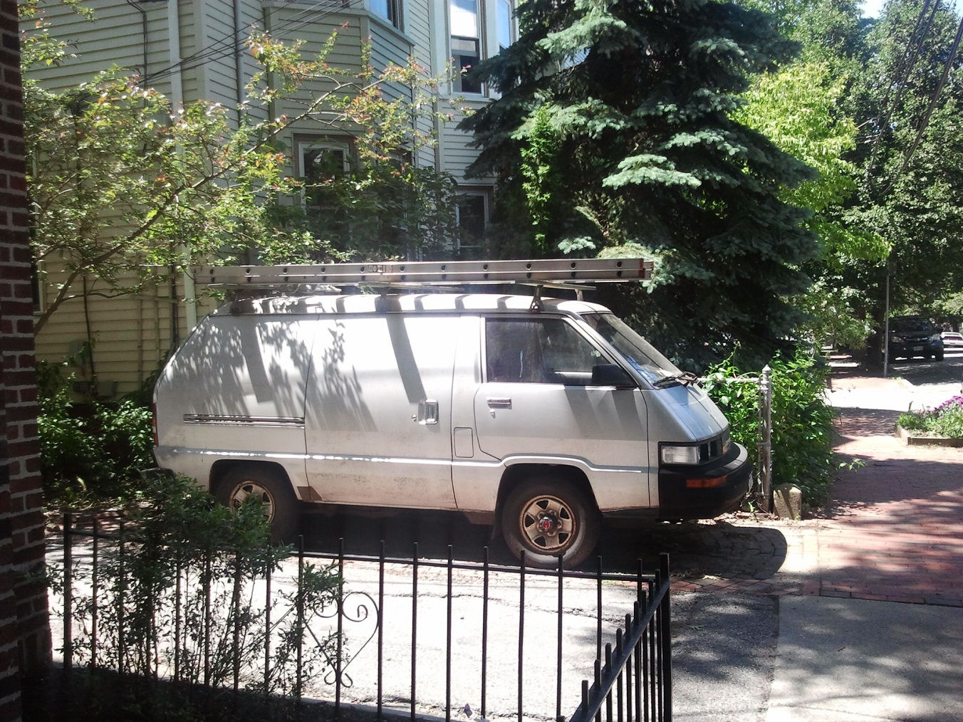
This trip was actually slated to be the very first major long distance haul for Mikuvan. None of us really expected to end up in the city – more like broken down in Rhode Island somewhere. I made sure to pack all the tools needed to service anything short of catastrophic driveline failure, and picked up a new compact spare tire (the stock full-size spare having rusted out seemingly years before, which I took in to get scrapped) beforehand from Nissenbaum’s up the street here.

I’m proud to say that it went down completely without incident. Now I have even less of a reason to dismantle the powertrain, right?
I even looped a new A/C compressor drive belt beforehand (came without one) to test the state of the air conditioning coolant circuit – and to my utter surprise, it blew totally cold. So there we go – all the amenities of a modern car with 9000% more “What the hell is that thing?”. By the way, the A/C still runs R12.
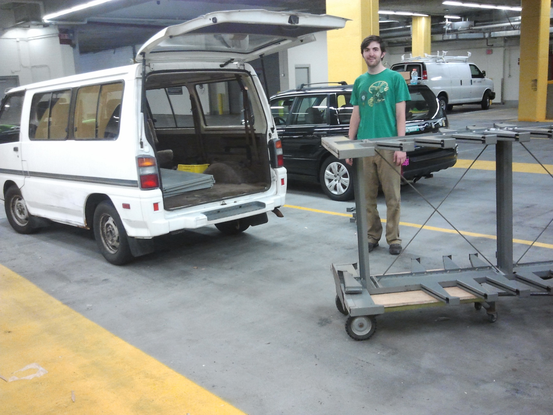
Above is a picture of the van right after arrival in Flushing, Queens. The only downside, of course, is that it has juuuuust enough horsepower to climb the Whitestone Bridge at about 50mph constant velocity with the gas pedal floored. Horsepower is not something hastily-modified JDM cargo vans are known for, but the electric version ought to fix that. I’m aware the speed limit on the Whitestone seems to be 30mph, but the crowd of delivery trucks and NY-plated private cars huddled around me seemed to beg to differ. I’m sorry, everyone, for having no power whatsoever.
Anyways, Nancy sums up our discoveries about Adafruit well. I no longer think they are made of magic and open-source genome unicorns, but infinity work and dedication.
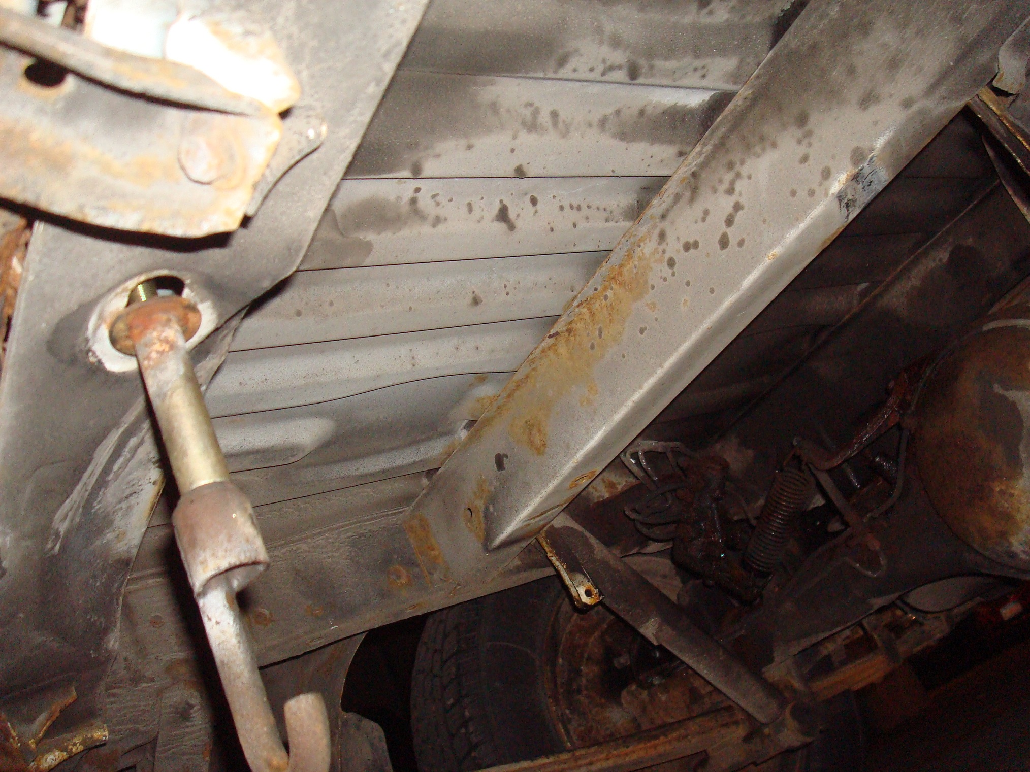
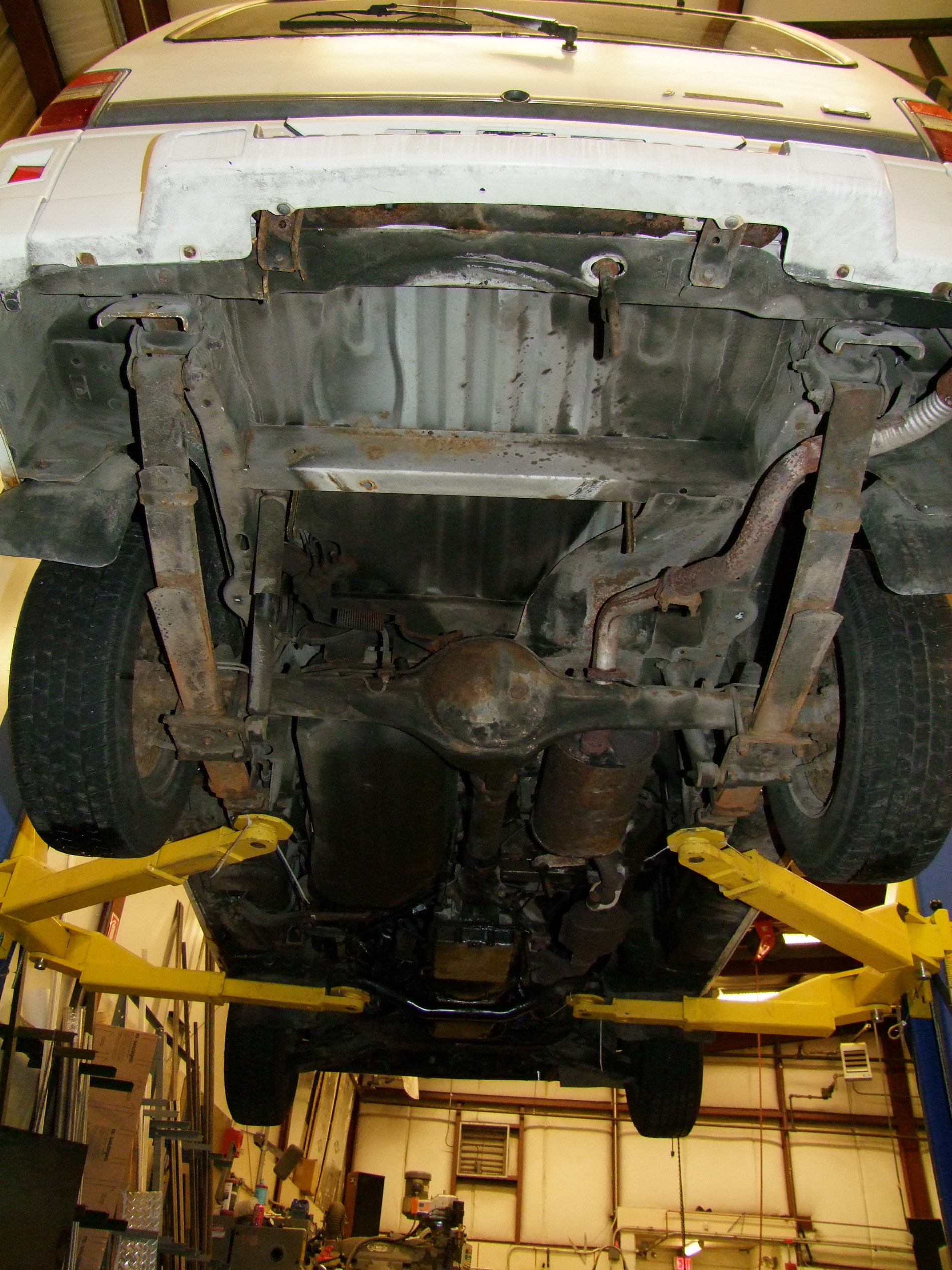
On this trip, I confirmed the engine oil consumption as about 1 quart per 700-800 miles highway driving, and more like 500ish-miles local (with more cold-starts and short driving trips). This is a staggeringly high amount, but I don’t think most of it is burning up. During my pre-trip inspection, where I recorded all fluid levels and made sure things weren’t jiggly and double checked my brake rotor-pad-shoe-drum-line-fluid conditions (since it should at least be able to stop, nevermind go) I discovered some fresh oil slicks near the bottom of the timing belt cover and that area of the engine block. This tells me that I probably have a leaking crankshaft front oil seal, and could explain the terrible condition of the timing belt discovered prior to Operation: BAD TIMING. It also tells me the current timing belt might not live that long anyway. The exhaust does emit a brief burst of smoke when cold-starting after a few hours of sitting, so it could indicate a number of other things worn, like the valve guide seals which were suggested by more automotively inclined buddies. I’m willing to write it off to 20+ year old poorly maintained engine. The oil itself does not show excessive signs of burning – the shade isn’t particularly dark, nor does it smell like burned fuel significantly, so I’ll say that most of it is just physically leaking out.
The fact that I hauled ass a total of 450 miles without any hiccups is amazing in and of itself, I think…
derpdrive
Hey, if I’m not going full-on electric right away, let’s at least check in on the thru-the-road hybrid shop-pusher module. DERPDrive hasn’t moved an inch in the past few weeks save for painting (in the same round as Melonscooter2), and that process looks kind of the same:

I picked up a handheld sandblaster from Harbor Freight (this one) to pluck all the rust and scale off the welded steel tubing quickly. Along with a jug of 80 grit aluminum oxide, it took maybe an hour or so to reduce the major frame parts to fresh steel. Here’s a picture of the blasting in progress. By the end, I’d created a small ejecta ring of sand, and I was basically covered in sand in every place imaginable. To supply the blaster, I borrowed a 25 gallon compressor from the IDC shop.

I hung up the parts using picture hanging wire and gave them three coats of the same etching primer used on Melonscooter space a half hour apart. With some of the lessons learned from Melonscooter’s frame, and a bit more advice from more legitimate painters, these parts came out far more even in the end than the scooter frame.

Next up were three coats of black (the same black, again, as used on Melonscooter since I bought like 5 cans of the stuff). Notice how I started during the daytime and it’s now the dead of night. There’s still some “orange peel” areas, but overall, everything dried totally smooth. I ran out of clearcoat, so DERPDrive won’t get the same crisp and shiny finish (But you’re never supposed to see it anyway…)

The finished parts after sitting in cooler, drier air for a day or two.

After the paint fully cured, I began adhering rubber strips to the front and rear of the structure, the parts which will be jacking on the van frame. These are some moderately hard (70A) and thin (1/16″) BUNA rubber strips I bought, being attached with contact cement. A thin layer of compliant material will aid in the attachment in a way two metal on metal contacts cannot – especially given that I won’t be able to torque down the jackscrews fully given that the van frame is still some pretty wimpy stamped steel rails. Again, if this doesn’t work out (like I start popping spot welds), I’m just drilling through everything and attaching them with rivet nuts.The C-clamps are to keep the adhesive fully engaged with the welded steel parts.I hope to assemble DERPDrive soon – I got into another one of those cycles of opening up multiple project threads, unfortunately…
melonscooter
The only work I’ve been able to get in on Melonscooter2 recently has been constructing and balance-changing the battery pack. I also prepared the motor controller, a KBS48121, and most other chunks of wiring for immediate installation. What I have been missing is the timing belt and pulleys – I ordered them last week, but of course waiting for shipping is the killer here. After I receive these parts, everything ought to fall into place quickly.

This is the battery pack in the middle of assembly. I waterjet-cut some 1/32″ copper bus bars for the task. One of them, to the left, has a chunk cut out of it to act as a last-ditch +250 Fuse of Oh Shit Amps. Unfortunately, I had used the wrong design equation values to make the cross section – I think this is actually good for something like 800 amps. Oh well…

Check the fully assembled pack. I added two 6S independent balance leads just to check cell voltages with for now – I hope this pack will be maintained infrequently enough that just cracking open the battery box and alligator clipping to it every few months is enough. Worst case, now I have one of these guys that I’ll make a balance lead jack for. These cells were in wildly varying charge conditions, so I had to spend a day or two just pushing buttons on balancing chargers, but now they’re all within 20-30 millivolts of each other.
colsonbot
Colsonbot… Colsonbot..
Does whatever a colsonbot does
Can he spin? Can he win?
No he can’t! He’s a wheel.
The Battlebots crew up here has reached critical mass. Full disclosure: The real reason for testing Mikuvan to New York City and back was so I can take it to Pennsylvania and back this weekend! The event in question is the PA Bot Blast, and the MIT crew will comprise myself, Dane, Jamison (whom I welcome to the MITrap), and freshly dragged into the craze, Ben.
If I thought trying to wing it up a bridge with only 4 people was bad, then climbing the Allegheny Mountains with four people and robots is going to be really adventurous!
Colsonbot has been in planning since a joyous all-hands dinner at Motorama 2013. Basically, the idea is to build an entire fleet of 3-pound “beetleweight” class robots and sprinkle them about the arena as a “multibot”, or multi-part entry, to cause trouble and mayhem. Oh, and they’d all be shaped like wheels. They would be otherwise functional “shell spinner” type bots, but the shell itself would be made of a popular robot drive wheel, the Colson Performa. I was basically tasked with whipping up a “mass produceable” prototype which we can make a box full and show up to any event with.
I’m proud to say that’s now well under way. To extend this post even further, here’s the work that I’ve done on the Colsonbot front in the past few months. Bear in mind that this sucker has to be ready to run in like 4 days. Luckily, all the parts are on-hand and ready, so I’m only doing some mechanical assembly work.
The way I planned Colsonbot is as a design which could be a successful shell spinner on its own, if only I didn’t put such a silly bouncy rubber shell over it. The drive should be 4WD for stability and traction, and the weapon drive should be as reliable as possible, though not necessarily the most powerful. Under all reasonable circumstances, it should keep rolling! Basically its strategy is to get smacked repeatedly and just roll away.

This is the basis of Colsonbot, a 6×2″ Colson Performa wheel. Typically you’d find these on 30 and 60lb (if not larger) bots. They were a staple of the early 2000s 60lb and 120lb pusher wedge – they paired well with the popular EV Warrior motor and some power wheelchair motors, so they were used widely by new builders. Now that the new builder typically starts in a smaller (e.g. 1 through 30lbs) class, they are less commonly seen than their smaller brethren in the 2 to 4 inch range.

One of the first things I did was to core out the Colson to as far as I thought was reasonable. This process should be repeatable for everyone in on this build, so I didn’t try making any fancy contours. The main body of the bot was consequently limited to about 4″ diameter x 1″ height, with an extra nub on top where the hub of the wheel is normally molded.
Check out those molding voids – someone just did not care at all. Typically, injection molded parts are rejected if they contain voids inside – a result of gas bubbles evolving in the material from impurities or just shitty sealing. However, an industrial caster is hardly a precision application, so I guess this is fine.

The nub in question. I found that the bore of the wheel was basically ready for two FR10 bearing (flanged R10 bearing with 5/8″ bore and 1 3/8″ OD) back to back, so the shaft support was potentially great. I hollowed out the bore as far as I was comfortable with given the Colson’s pseudo-spoked core.

Cored vs. stock, with FR10 bearing. If you actually want to buy these, be aware they are rarely sold as “FR10″ (in the vein of FR8 1/2” bore bearings, which are very common). Try searching G10 or FR2214 bearing instead. By the way, these are exact swap-ins for the horseshit bearings in common Harbor Freight wheels, like these or these (my favorite!)

This is where the fun part starts. Time to try stuffing an entire robot drivetrain into the hollow cavity of the Colson! The only motors short enough for the job were the Sanyo-type “micro” gearmotors sold by a number of places, including Pololu. Literally no other common robot motor (i.e. which we could all buy a bundle of) could fit, even in an “offset” 2WD application, while leaving enough space for the weapon motor and batteries, at least to my sophisticated (…apparently..) specification. I have my own doubts about how robust these very tiny motors will be given the high-impact application they will be in, but we shall see. I purchased a handful of 30:1 units for testing.

After some component shuffling, this is what I came up with. It’s actually shaping up to be a great bot. The four motors are placed in a nearly square wheelbase for best handling, and the weapon motor is off to one side. I decided on a spring loaded slide assembly to keep constant pressure on the shell, which has not been modeled yet.
The hardest part about this thing is the battery. I wanted to fit at least a 1Ah, 3S lithium battery into it, but sadly there were just no options available which could fit in the space required. I had to settle for a 800mah pack from Hobbyking, and even that (as you’ll see in a bit) was pushing it.

Wow, now we’re getting somewhere. I’ve designed this frame to be very quickly blasted off on a 3D printer. As a result, it’s actually the most product-like thing I will have built, yet. The body is all plastic with lids and snaps covering the important bits.

Now with more colson and other parts. The left part of the frame is where the motor will mount – it will be on a little dovetail slide assembly.

This is the mechanism modeled in more detail. I typically just model big blocks and geometric representations of parts until I get to them in earnest. The motor will have a “tire” made of rubber O-rings mounted around the outside. The motor in question is a Hacker A20-50S, first generation (i.e. without the obnoxious tailcone) that I have a few of thanks to my weird airplane friend Ryan. It was the only motor I could get in short order that was short enough yet had enough power. In the”mass production” Colsonbot, this will be replaced with an equivalent Hobbyking shady outrunner.

After the big mechanisms were settled, I began hollowing out cavities for other components and making wire guides.

Here’s a picture of most of the guts installed. The master parts list rundown is:
- Leftover Turnigy Plush 18 for the weapon controller
- Hacker A20-50S 1Gen for the weapon drive
- Vextrollers for main drive
- Hobbyking T6A receiver guts for the receiver
- Z800 3S 20C pack for the battery
The center axle is a 5/8″ fine thread bolt with the head machined down for fitness and hollowed out for weight. I don’t think there will be any problems with robustness for the joint between bolt and plastic frame.

I’ve moved onto designing covers and plates here. The motors mount only using the frame members to clamp them in place. They’re square and of a known length gearbox-wise, so this was actually quite easy. It is the same system in use on Pop Quiz 2 to clamp its own 4 Sanyo-style micro motors.

With the battery cover done, it was fine to export everything as STLs and 3D-print all the parts in ABS plastic.

I popped these into a Dimension 1200SST and ran out the last bits of a cartridge with it. I would have tried this on our shop Replicator 1, but just had this sense of hopelessness from the amount of weirdly sticking-out parts.

Test fitting parts now. The motors snap right in – I could almost just run these as-is without the bottom cover!
One issue I found was with the 3/4″ Dubro airplane wheels I bought. I’d never drilled them out before – Pop Quiz 1 used the same wheels back in 2005, but with their stock 2mm bores. It turns out their hubs are no more than about 3.5mm diameter in the center, so when I drilled them to 3mm to fit the Sanyo-style micro motors, there was nothing left to drill and tap into.
Well damn. I quickly whipped up a set of 3/4″ o-ring wheels to be 3DP’d to get around this issue.

Remember the battery? Hobbyking’s dimensions should be considered to be +1mm in all directions in the worst case. I designed this battery compartment using their given dimensions, but when I actually got the battery, it didn’t fit!
Just barely, however. The heavy plastic wrapping they use to shield the pack against punctures sort of got in the way. So what do you do in this case? Cut the damn thing up and just use the 3 cells totally naked. Hey, they’ll have some thicker plastic armor once in the bot anyway. I intend to do this to the 3 packs I got for this thing as spares.
Colsonbot should be all together in the next 2 or 3 days, so definitely stay tuned for this one!