Überclocker Update 6: The Beat Goes On

It’s been a while since I’ve had an entire day of solid bot work. Most of the “weird machining” on Überclocker is now either in process or over with. A few tricks and workarounds made things go alot faster.

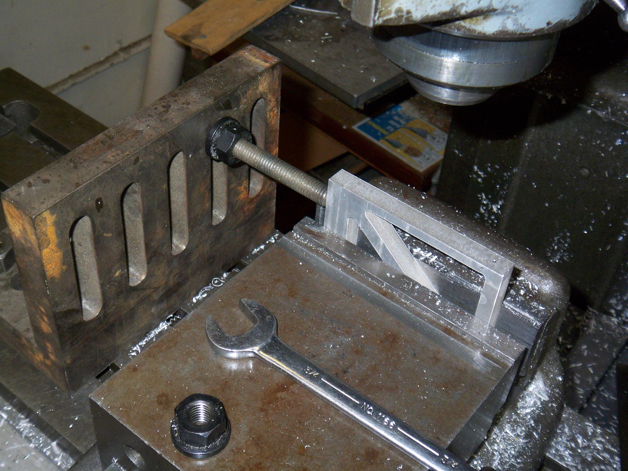
…like this one. After exactly one part, I got sick of having to re-zero the machine after flipping the piece over. And so I had to devise some crazy rigged solution as usual.

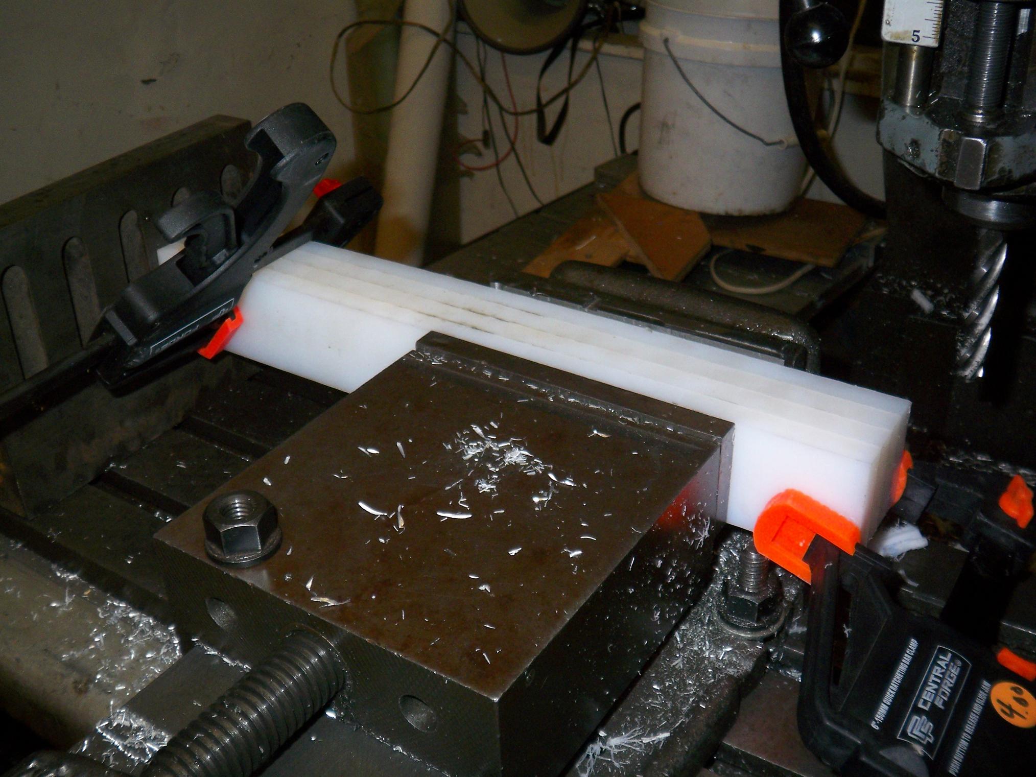
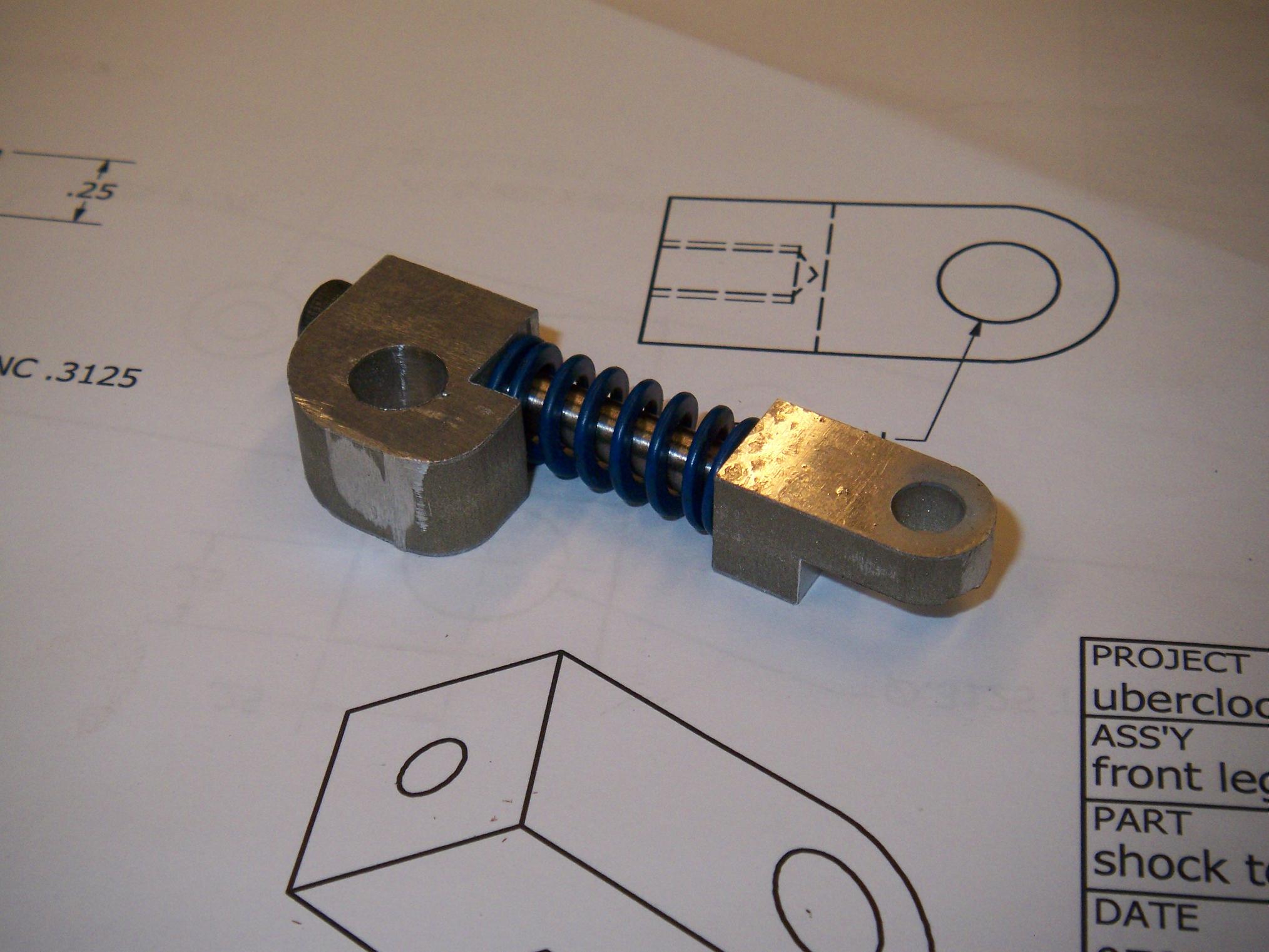
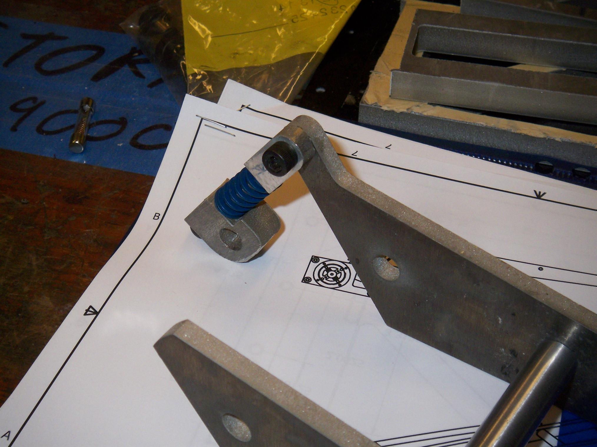
Fortunately, this time, it wasn’t too rigged. A few 90 degree angle blocks were hiding in a shelf corner, so I cleaned the industrial grunge off one and mounted it to the mill table. A bit of threaded rod and some malleting later, and I had a makeshift “workstop“, which is a little stick-like thing that is used to accurately reposition a workpiece after removing it from the vise.

It’s slightly more than a stick, and looks like it can actually stop a small train, but oh well.

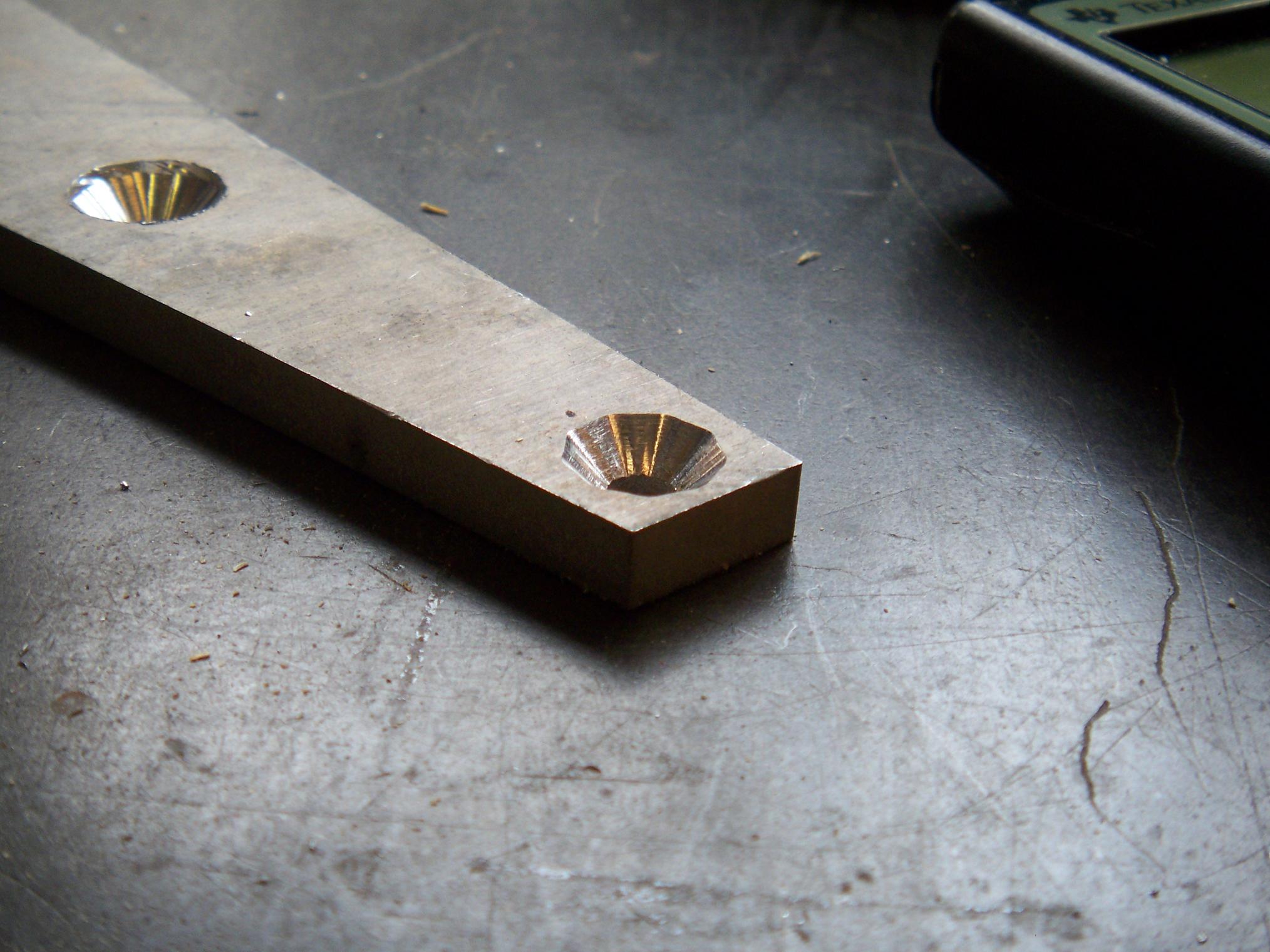
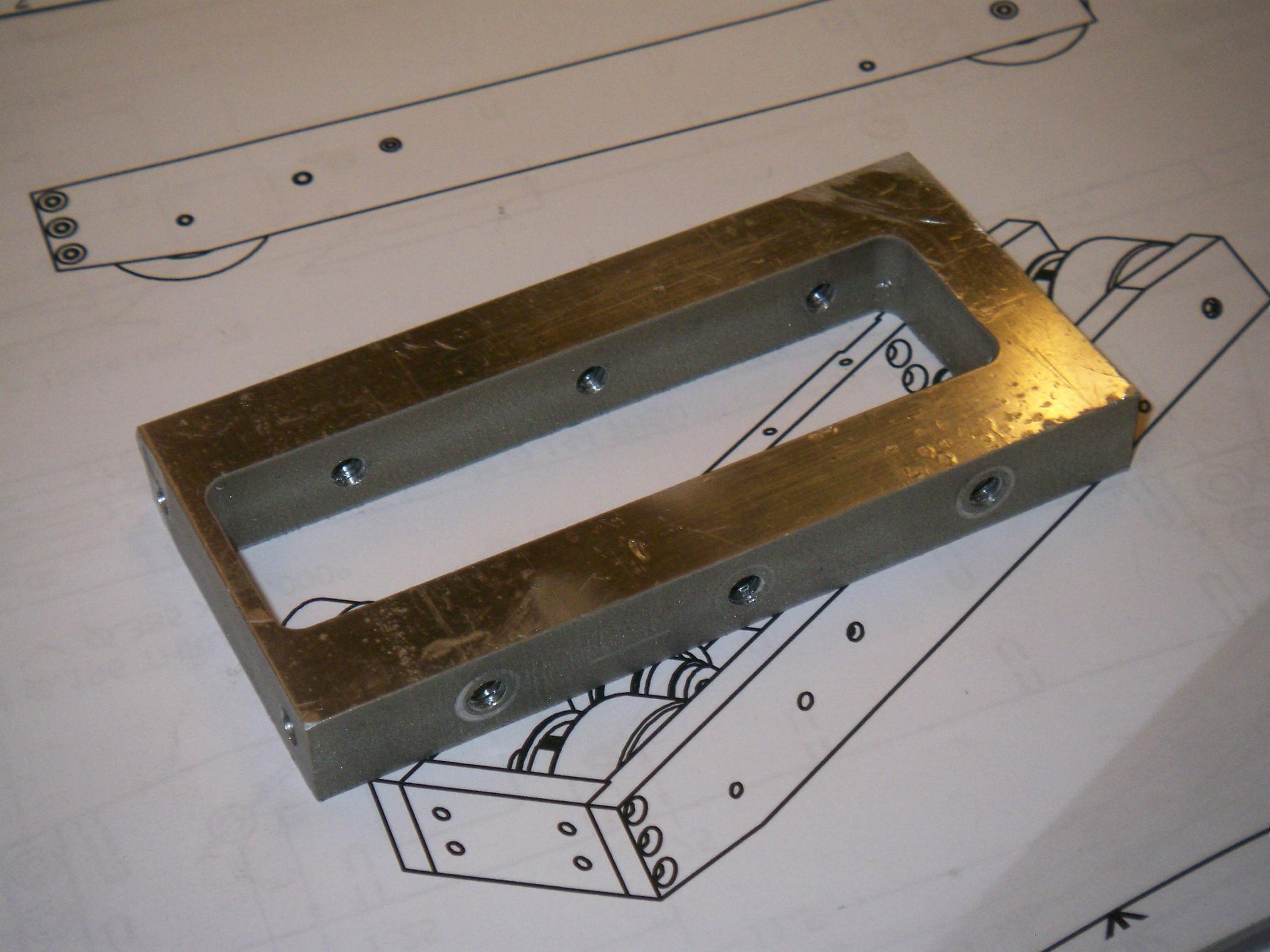
How do you drill a 9 sided hole? With a countersink. Although there were a dozen or more countersinks in the Toolgasm, none of them are odd-fluted. The result: chatter like Paris Hilton with a new cell phone.

It probably didn’t help that I just freehanded this part.

Fr0k spacing things all threaded. The same part that got me sick of edge finders also got me sick of manually tapping. Solution: spiral-point tap and a cordless drill. Spiral point taps seem to be an order of magnitude stronger than their four-fluted hardware store cousins, clear their own chips, and a nice handful came with the Toolgasm. I selected a TiN coated #10-24 and tore through all 24 threaded holes in a few minutes.

Unfortunately, 16 of those ended up needing to be clearance holes. Oh well, better that I thread 16 extra holes than drill 16 holes too large.

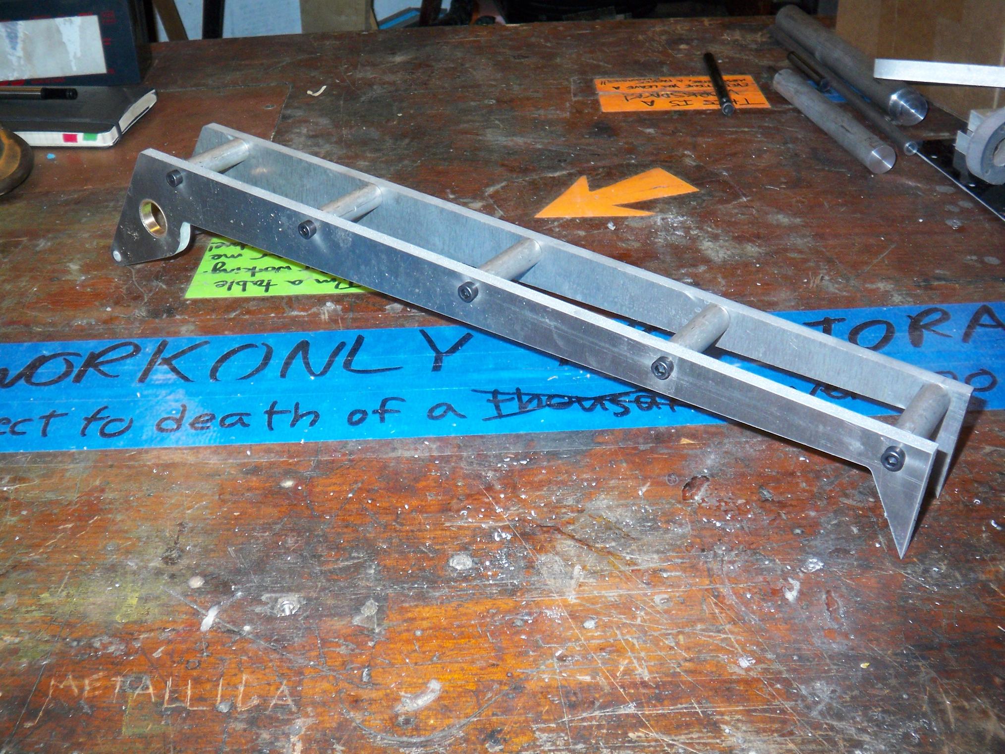
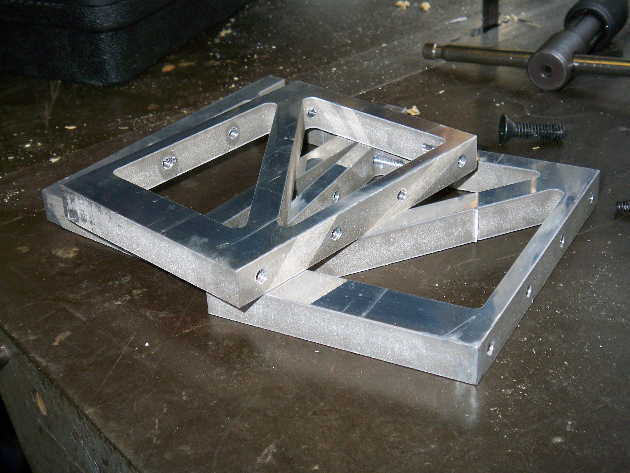
In another fit of absurdly industrious machine work, I finished up the “upper fr0k”. To my chagrin, I discovered that 800 grit fine sandpaper produced the same shiny finish as a fine power feed. So I just made a bunch of standoffs from raw half inch aluminum stock (of which there was a convenient 10 foot stick, found behind yet another unsorted shelf). The front support leg standoffs were made this way. I decided to not bother shining up the spacers for the upper fr0k.

These were also power-threaded with the same #10 tap, on the lowest speed setting of the lathe (something like 100 RPM). I set the belt tensioner a bit loose such that when the tap bottomed out, the spindle stopped turning.

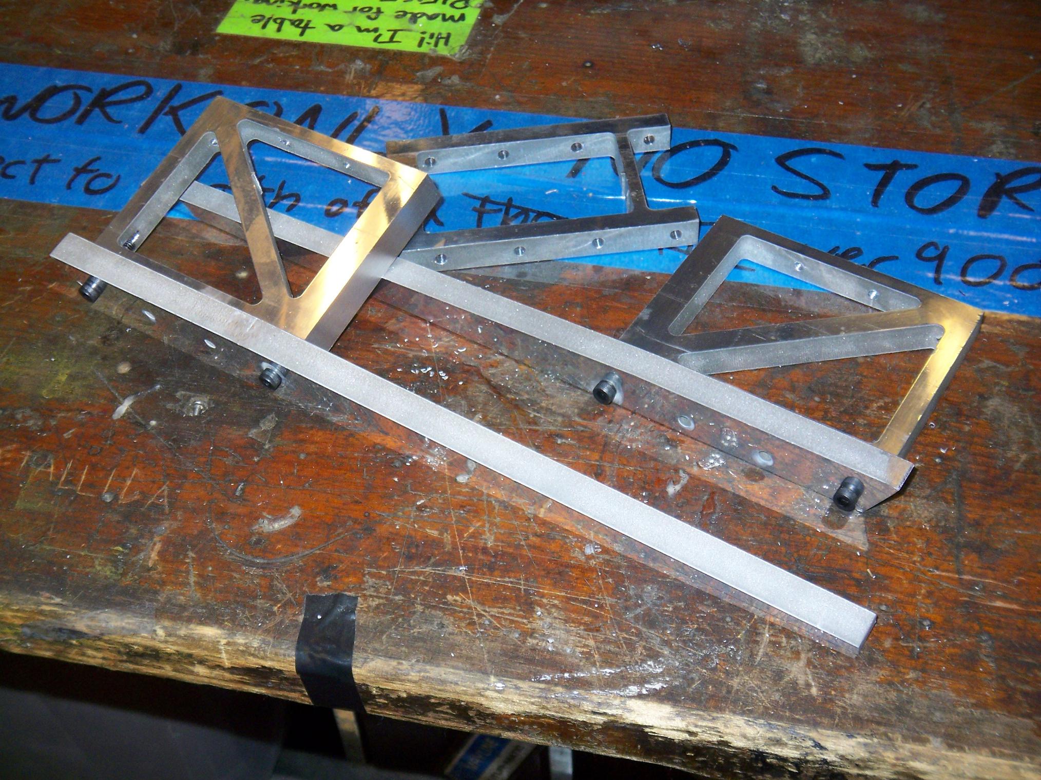
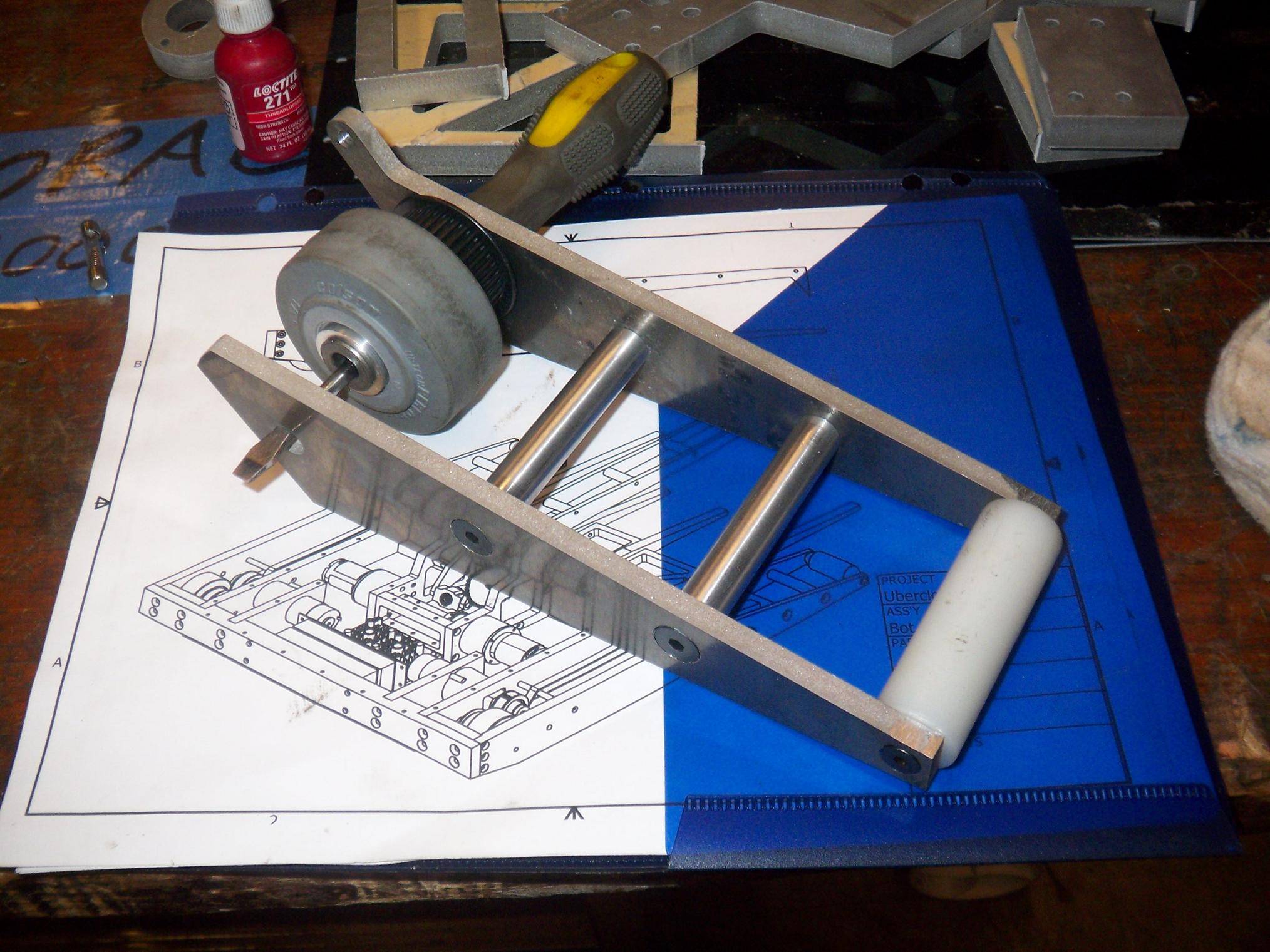
Outer fr0k tines mated to their respective spacer things. The 15 degree lead angle on the spacers have been milled in this picture, and is just barely visible (They won’t do a thing… why the hell did I even design those in?)

After putting down the fr0k, it was time to attack the first “weird machining” task – making the 10 degree front and rear slopes. This was made decently difficult because the parts were huge (15″ long UHMW) and I had no angle blocks, angle vise, angle plates, or any other implement with the word “angle” in it besides “angle grinder” which didn’t help one bit in this case.

I ended up pulling the same stunt as when I machined the 45 degree front slope for Pop Quiz – tilting the head and using Interesting Trigonometryâ„¢

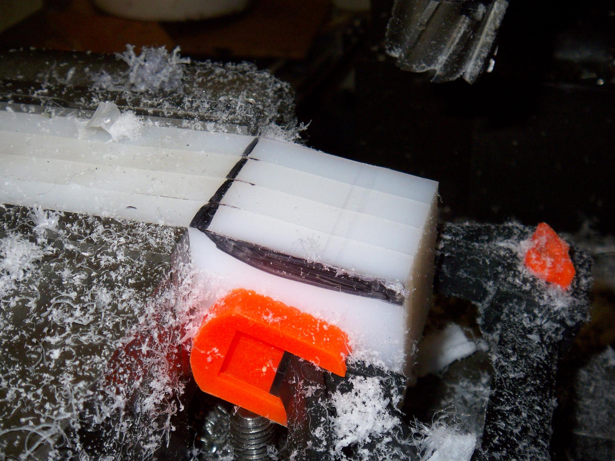
It worked pretty well. For every n” I moved the table up into the cutter, I had to move the x direction n / sin(10°) to keep the cutter face on the same plane. Repeat k times for k a small real integer constant and a 10 degree slope emerges. Then flip the part over and do it again.

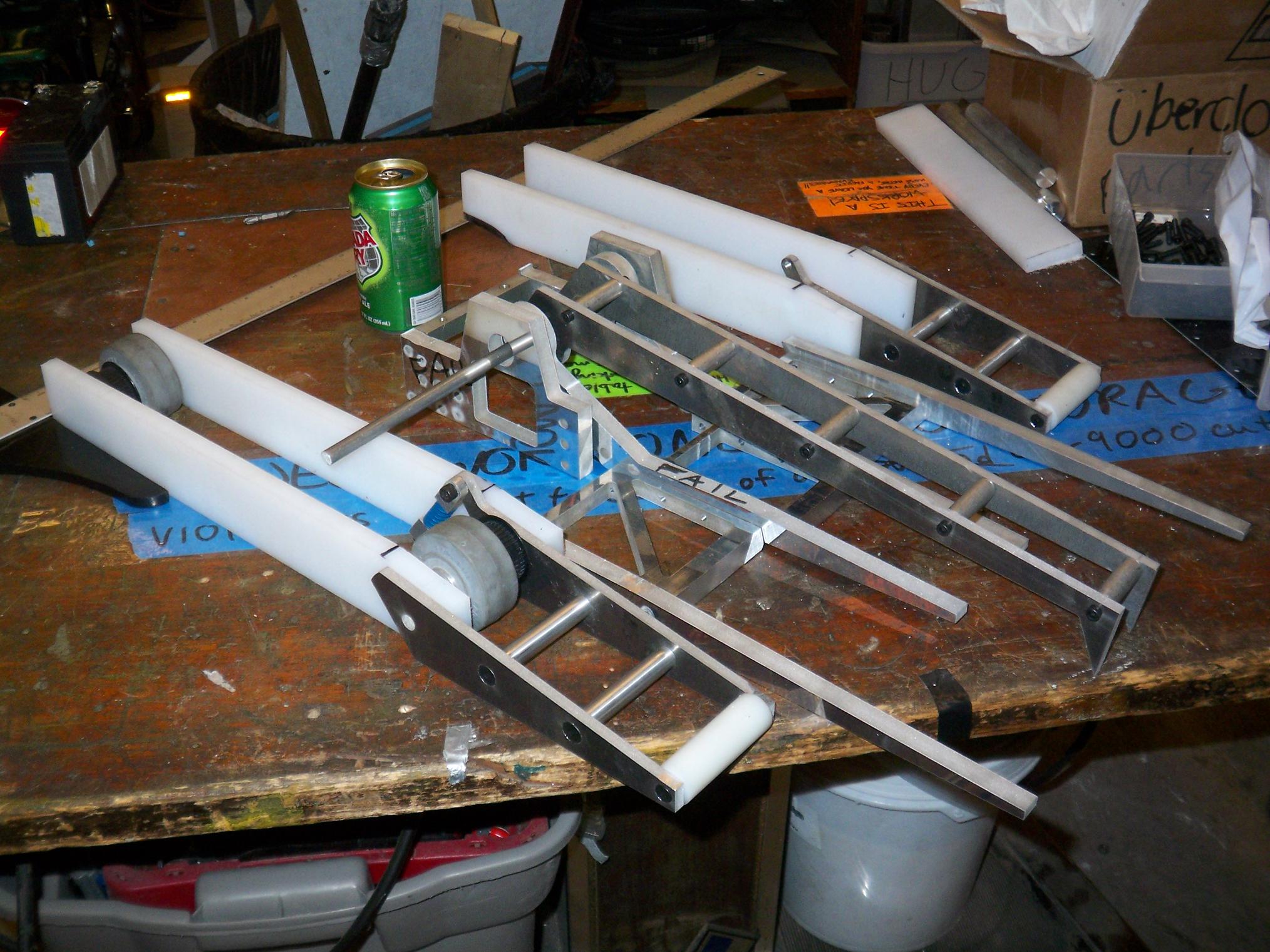
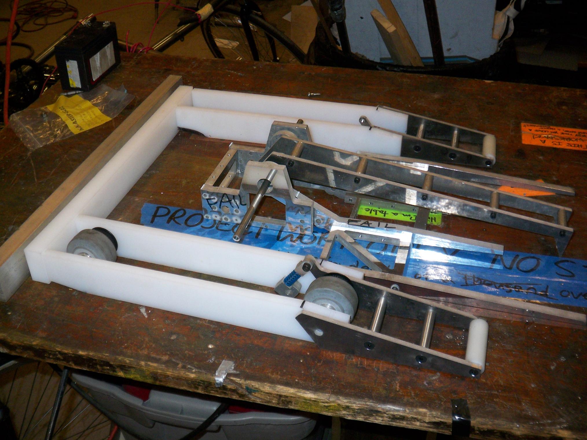
After all four rails were roughly shaped, it was PRETEND-O-BOT time! Hey, it looks like something.

This thing is absolutely enormous. That’s a 36 inch T-ruler I used to position the parts. The chassis itself (UHMW only) is 15.5″ long and 20″ wide. The fr0k extends way out in front and brings the total length of the bot to 27 inches. That’s pretty nutty. For comparison, TB4.5MCESP1LOLBBQ is exactly one foot square (one square foot?!) with the wedge bringing it to 16″ long and 16″ wide.

While I was still on bot-gasm mode, I trimmed off some of the 1″ UHMW barstock for the back end. Also notice the similarly-sized aluminum bar. I originally purchased this for the LOLriokart (whose drivetrain parts are still in transit. Thanks goes out to Bank of America for assuming any purchase I make over $100 is some kind of fraud unless I tell them beforehand that I’m buying something more than lunch)

I’m debating whether or not to just make the back end of the bot out of aluminum. The bot is 7 pounds underweight in the design, even with most of the big hardware accounted for. Since there’s no way I can fill up at least 6 pounds just with wires, Loctite, and duct tape (by accident), it could stand some more solid material. Aluminum would also double as some ballast to keep the bot on the ground during a powerlift.

Stay tuned for more! United Hobbies/Hobbycity should be pitching some 4AH lithium polymer packs at me soon.

Überclocker Update 5: Little Round Things Edition

Today was a wonderful day filled with little round things.

I’ve begun working on Überclocker’s minor parts as I await another run on the waterjet (and more aluminum) to finish the fr0k. This is slightly more work than I anticipated, and with my days taken up by both the Media Lab and the MITERS-alumni-generated giant-solar-mirror-squeegeebot-building startup, free bot time is actually getting fewer and farther between. There’s nothing meaningful at that website yet. However, should you need giant squeegeebots for cleaning your multi-square-metre shiny, smooth surfaces later on, please give us a ring.

Here’s a completed “front leg” assembly, composed of two waterjet-cut pieces and some standoffs. I have become a fan of the “2D assembled shapes” building method since most of the work is done by the waterjet cutter. I only had to countersink the side plates (and a good 5-axis waterjet can even do that o_O)

With the new tooling setup on the lathe, I can make a simple standoff in under 30 seconds. A screw machine can do this in under 3 seconds, but I’m also not making 10,000 standoffs in a single breath.

The corners on this will probably be chamfered inwards later on in order to allow traversing of the Robot Battles stage. The plastic roller is 1/8″ smaller  than I intended since a 7/8″ UHMW round was sitting in a bin, but I would rather it be slightly smaller than dragging on the ground constantly.

I’m beginning to get a sense of how absurdly huge Uberclocker is going to be.

Next up were wheel hubs. The front and rear wheels are identical this time, being indirectly driven. I also cored out a pulley for each hub. 2.5″ Colson wheels press directly on the hub OD, and little bushings fit on the ID.

I remember when making little round things like this was a OMG SRS BIZNESS and took 40 miles of driving and all day to do. Oh, wait, that was last year…

Here’s a completed “coilover” thingie. I’m really not sure what to call it – it’s not a shock absorber of any sort, just a springy plunger thing.

And it latches onto the front support accordingly. The back end will be fixed to the frame and the front supports will float freely on an axle. The spring allows for compliance with the floor obstacles at Robot Battles, but when the bot raises an opponent, they will deflect more and push back with correspondingly more force, hopefully allowing the bot to balance. I can upgrade to stiffer springs if they prove to be too weak.

I also made a motor-side pulley with hub. The drive belt on each side will wrap around all three pulleys and a tensioning roller in a serpentine configuration. I have yet to design a belt tensioner, since I don’t know exactly how long the belt needs to be, and ordered a pair just based on the combined pitch lengths of the pulley system.

The cored-out pulley presses onto its own aluminum hub which is threaded on the inside to mount on the drill motor output shaft. I managed to fuck up this part twice – once by drilling through the wrong side and the other by mistaking a diameter for a radius and cutting twice as deep as I needed to.

Fortunately, MITERS is resplendent in 1″ aluminum rods.

I now have an appreciation of free-machining steels.

Here’s a completed axle-standoff, made from 3/8″ steel. They’re threaded on the ends so screws can attach through the frame and lock the axles in place while holding the frame apart the right distance.

I had to make this part twice also – the first try was with some 3/8″ “printer rod”, which is a sort of weird medium-carbon steel. This must have been a serious printer, because the rod was actually case hardened and uber-polished.

Meaning: No tools I had could touch the thing radially. I actually had to cut off a 3″ section on an abrasive saw to begin machining.

…like that. This is a nice picture, too. If you like long-exposure shots of burning metallic compounds, also check my Fiarwørks Day picture album.

Regardless, even after that, it was still an enormous pain to face to the correct length, chipping the tip off one of the HSS bits (a quick regrinding brought it back to life). It also ate a drill bit I tried to end-drill it with.

I gave up on that and dug around for some better material, and came up with a 3/8″ cold roll steel rod, which went quickly and quietly. CRS not being much stronger than 2024 aluminum, I wondered why I didn’t just make it with an aluminum rod.

…right, because aluminum galls like a motherfucker. A dash of 400 grit sandpaper to the 3/8″ steel rod and the wheel slipped right on.

Lastly, in non-round-thing adventures, I finished processing a part of the fr0k assembly. This is the rear “connecting block” between the two arm towers, and was one of the few pieces that I could still salvage from the ill-fated 1/2″ aluminum plate. The reason is because nothing critical is actually on the front face of the part.

Double-sided features on parts are a pain, since I had to flip the thing over and re-zero everything to make the holes on the opposite side.

Stay tuned for more!