Harbor Freight! Brushless! LITHIUM! IN THE SAME SENTENCE?! Words I and many others never expected to hear, much less experience in person. But here we are, in $CURRENT_YEAR, where a Harbor Freight product contains this…

Welcome back to BEYOND UNBOXING, where Charles buys small consumer / industrial devices to take apart and cruelly comment on their parts and construction. I believe in looking for parts in unexpected places and using them across intended industries, so the intent of the series is to inspire people to go “Huh… well I guess you could use it to drive my electric combination briefcase & portable document shredder”. I only reverse-engineer as far as it’s convenient to do so, because the rest of it is your job. My previous ventures in this series have all focused on building sillier go-karts and stupider robots, and this shall continue the same trend.
Two years ago, I took apart and analyzed the Ryobi brushless chainsaw, back when these things were still relatively new and fancy. There’s been a recent explosion (and not even in the lithium sense!) of brushless lithium-ion outdoor power equipment market, which is great because those tools are more likely to have motors on the scale of one human butt-moving-power, or the 1+ kilowatt range. Now that Harbor Freight has even gotten in on the game, that’s when you know the concept has matured! Sorry Harbor Freight, please still love me.
I was clued into this when I was on my semi-weekly pilgrimage to Harbor Freight (ask anyone who knows me – this is real) and talking to them about #season3 plans when I asked about when Harbor Freight was going to start going brushless.
> mfw "We got something in 2 weeks ago you should see!"
I forgot what it was I went to Harbor Freight for, but I sure as hell left with a chainsaw for some reason. Introducing the 63287 Lynxx 40V 14″ cordless chainsaw!

Welp… it begins again. I see that the “GAS-LIKE POWER!” fat-substitute additive marketing line has since been taken over by claims such as “BETTER THAN GAS!”. I can think of a few things better than gas, such as nausea and indigestion. This is the presentation – unlike the Ryobi (whose packaging status I haven’t checked in on), the whole chainsaw ships in a box without the chainsaw part sticking out.

That’s because it ships disassembled, with the saw chain in a separate baggie and the bar dismounted. I think this is better for the product’s survival rates. Anyways, once you get inside, the presentation becomes a bit messier, with stuff taped in place to other stuff. But we’re not here to wax our neckbeards over how the product appears in the box – no, not all. After all, I would have been satisfied with a presentation any more nuanced than Harbor Freight staff literally throwing the chainsaw at me. I would even be okay with it if it were off at the time.

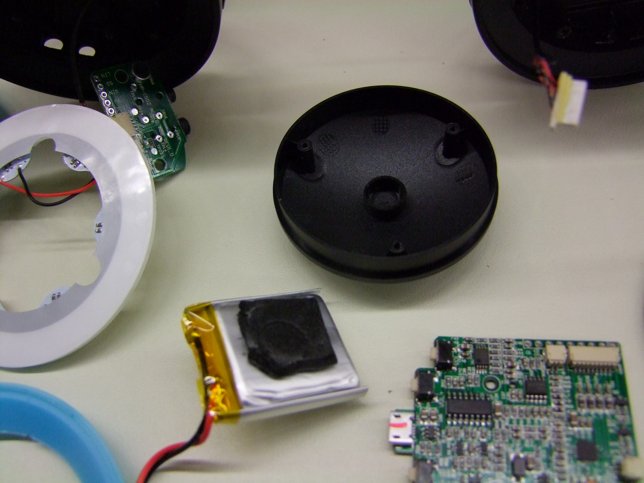
Here’s all the parts! Bigger white box is the battery charger, little white box is the battery itself.

Well, since there’s still boxes, let’s unbox them! This is the battery charger base and battery. We’ll be checking out what is going on inside both of them. The battery feels awfully small for the saw it’s supposed to be running, but that’s lithium being deceptively power dense, so I won’t prejudge yet. The battery charger feels very light – a sort of “We know this is 1 PCB inside here, but here’s our attempt to make it look like it houses a miniature nuclear power station!” design language.

The battery comes apart with just four Torx T20 screws. Nice try, product design gods. The first thing we notice is that yes, there are in fact 10 cells in there – 10 of what self-reports as Samsung INR18650-25R cells, quite a reasonable choice. The 18650 market in my opinion is just as, if not even more competitive than the flat cell market, since it’s a singular form factor used in multiple industries which production engineers can really mutually stroke over. The best commonly available 18650 cells are 3.6Ah and But Charles, this site is selling a STOP LINKING ME SHITTY CHINESE “5000mAh” 18650s BECAUSE THOSE ARE ALL FAKE. Experimental pre-release ones, as of my last knowledge sync, were approaching 4.0Ah per cell legitimately – so who knows, maybe one of these days.
The next thing we see is a 40 amp fuse.
Nope, not an electronic fuse made of MOSFETs, or a cutoff circuit made of the same. Just an honest-to-Baby Robot Jesus 40A ATO fuse, soldered in place. You blow it, you’re done! Unless you’re me and selectively bypass your fuses for extra hilarity in life. The low-cost-ness was starting to show through.

The OEM of this battery is shown on the silkscreen of the PCB. They also seem to be the OEM of the whole unit. Holy hell, they have a Brushless Drill. AND A BRUSHLESS SAW. And their choice of color coordination is based around MIKU BLUE AND BLACK! Damn, did I start a Chinese tool company and forget about it or something?
YOU KNOW WHAT THIS MEANS? HARBOR FREIGHT BRUSHLESS DRILL CONFIRMED Serious talk though – their 40V blower is the same as the Harbor Freight 40V brushless blower. I found this unit less enticing because it’s more or less a ducted fan in a tube. But I really hope we start seeing the brushless drill soon.

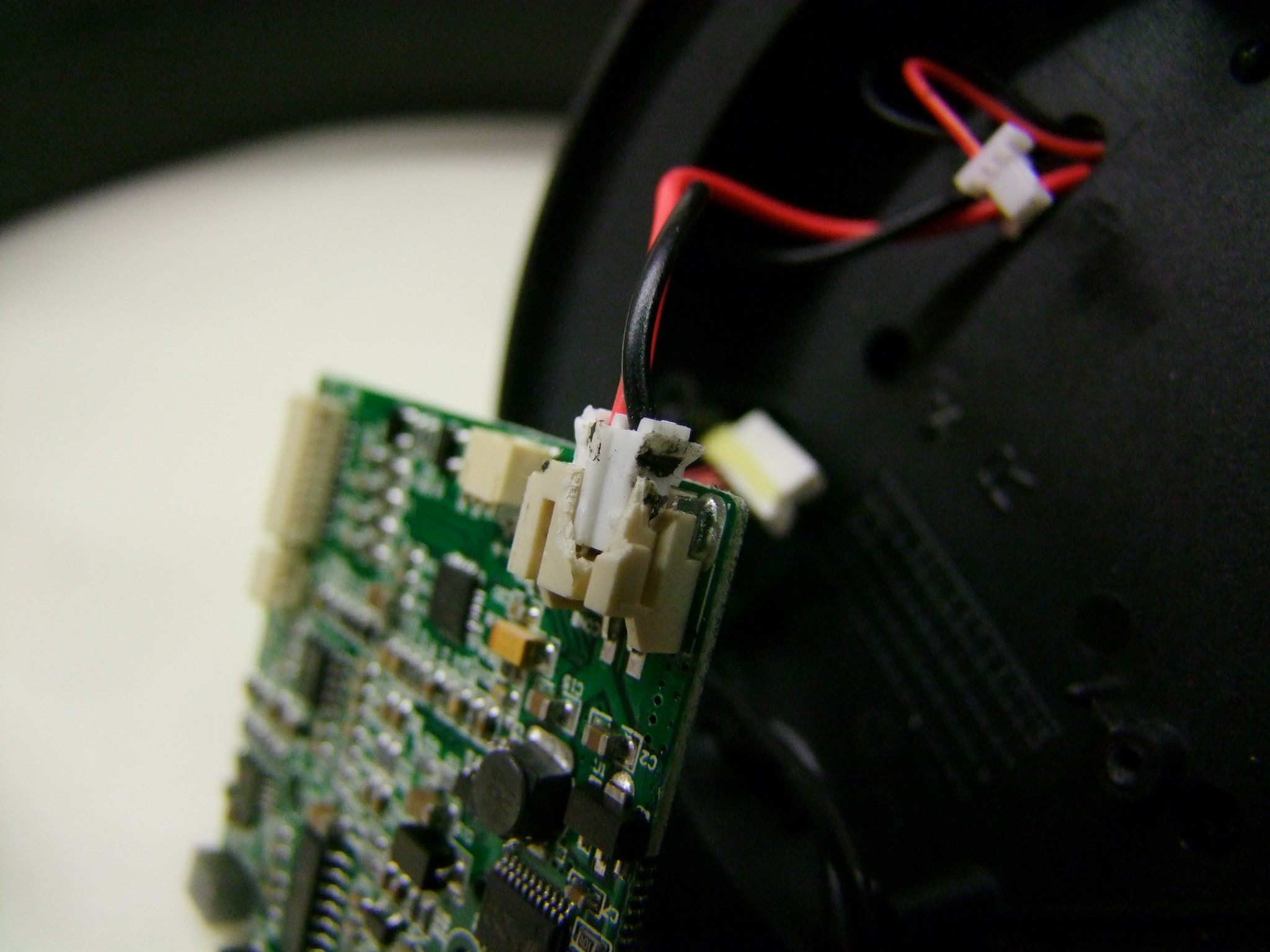
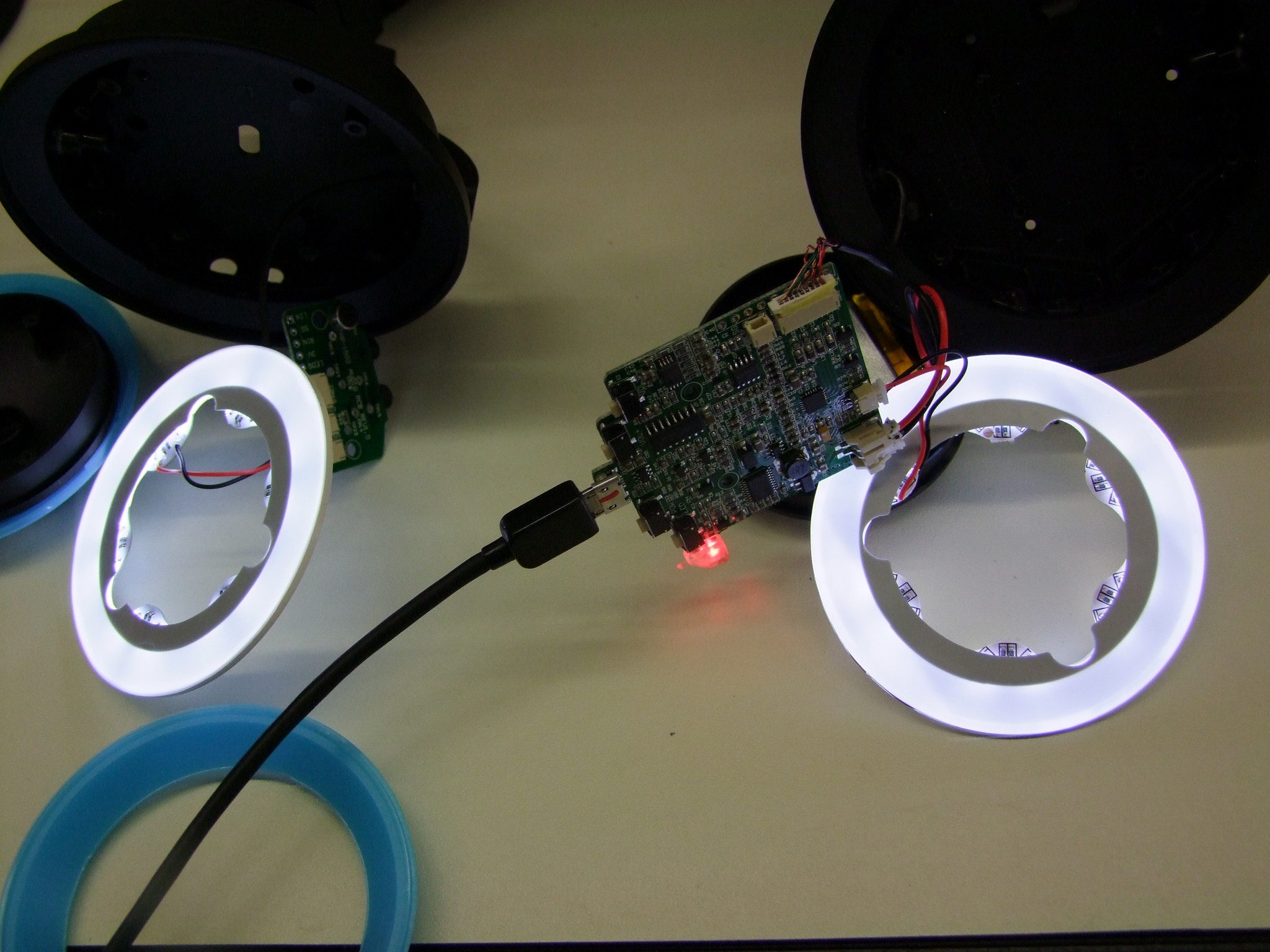
Fancy little fuel gauge light on the battery, a normal characteristic of lithium drill batteries everywhere. This fuel gauge is powered by a Chinese 8051-like microcontroller
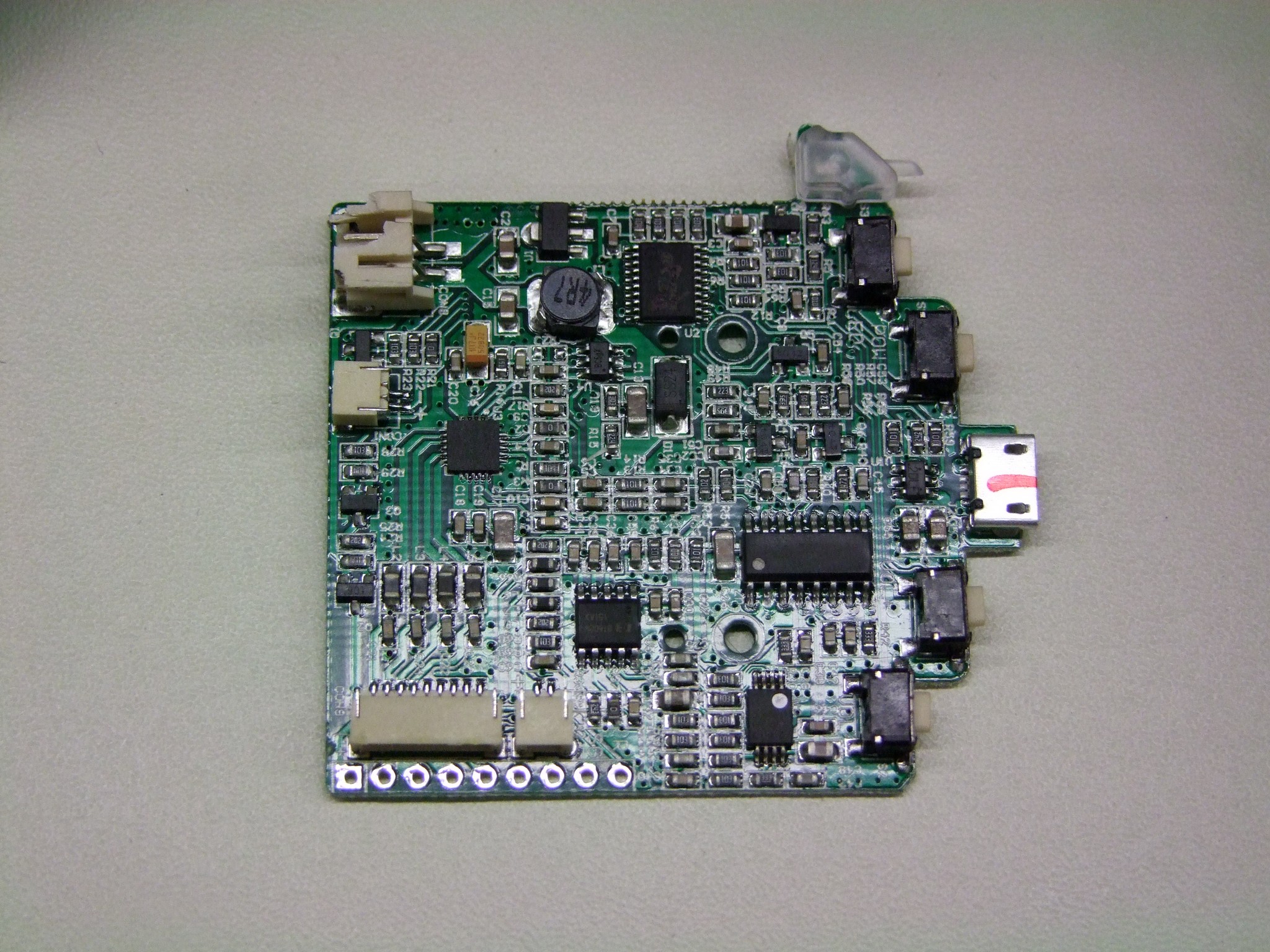
Something felt wrong, though. I inspected the board thoroughly for any signs of current measurement devices, which would let you ‘coulomb count’ and keep track of the battery state of charge. But there was no such hardware. Nor were there even cell-level taps so the controller can sense what the battery cell charge levels are and accommodate for them. You usually see this in the form of large power resistors that are shunted in and out of higher-voltage cells. The controller keeps the cells within a certain charge variation window, or can declare the pack dead to the power tool if one cell takes a dive.
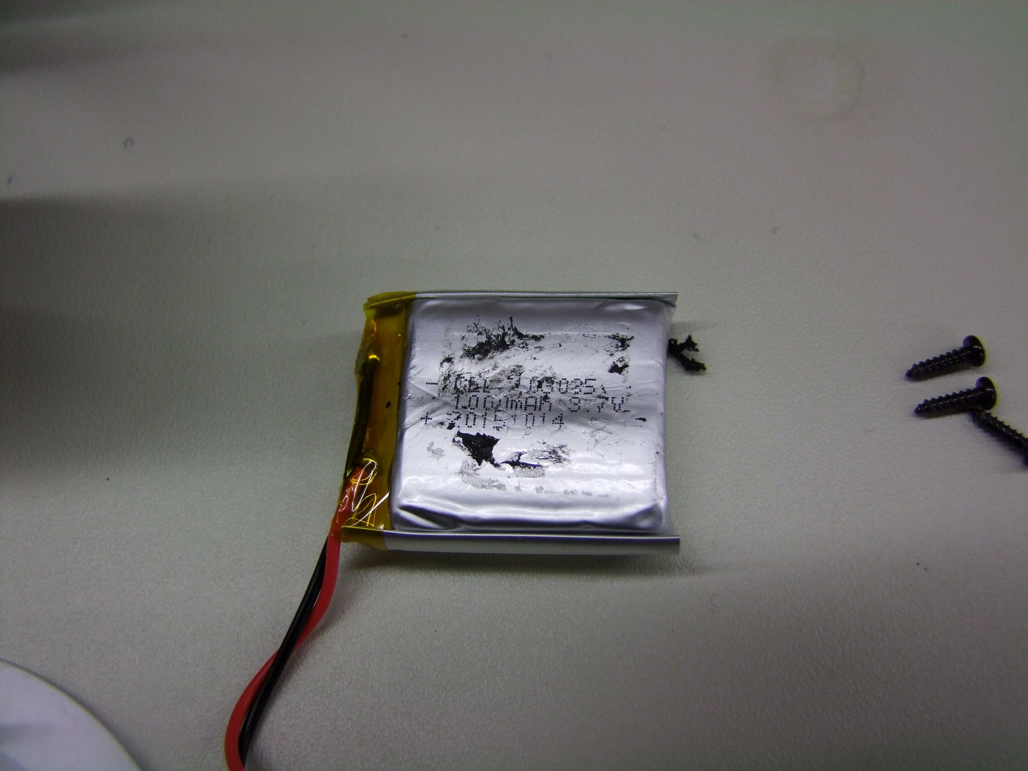
I couldn’t see any circuitry at all that could be described as a battery management system. This, plus the presence of the internal 40A fuse (that needs disassembly and soldering to replace), makes me fairly sure that this battery is running by the Grace of Robot Jesus alone. The little fuel gauge light is likely just a voltage sensor.

I even stared at the underside of the board to see if there were parts I missed. Nope – besides connector pins sticking out, I could see no signs of cell taps, current sensors, or bleeder circuits.
Now, truth be told, there is precedence for un-BMS’d lithium batteries. In fact, my old e-bike battery was a solid blob of 2.4Ah 18650 cells with just a thermistor wire coming out besides the main charge-discharge wires. It’s stayed working for the past ~5 years and continues to take in 6 to 7Ah every charge. If all the cells are well-matched for characteristics, then over their design lifespan they will never drift apart in charge level enough to be dangerous. Plus, there’s a hard fuse on the outputt in case of shorts. So this is some pretty intense cost cutting, or perhaps cost tradeoffs being made; purchase better quality cells, skimp on monitoring hardware.
I’m actually not sure how I feel about this. With all the recent chatter of explosive phone batteries, seeing a pack as ‘naked’ as this is a little concerning. However, even with a BMS, if you have a counterfeit or defective cell that just decides to let go, there is actually scant little you can do to prevent exothermic events from progressing. This is part of the Curse of the Hoverboard SEG-THING, DAMMIT! we experienced last year; I’ve taken apart SIX of those things. All of the batteries have a similar BMS card on them, and as far as I can tell, they all work. But if one counterfeit cell sneaks into your poorly verified and documented supply chain, you’re done and your product’s reputation is ruined.
So really the question is how MUCH do we trust this OEM to only use well-matched cells? WE REPORT, YOU DECIDE.

So up until this point, I’ve not actually shown how the two mate together. Like basically every tool battery these days, they slide together and lock, needing you to squeeze the latch to release. Nothing surprising here!

Here’s the inside of the charger after disengaging the four T20 screws holding it together. The “this is one board” theory is revealed to be true. Not that it’s surprising, since welcome to 99% of all consumer electronics today.

There’s no intelligent battery stuff going down here, really. It’s a 42 volt power supply, probably with constant-current and constant-voltage modes that automatically switch and that’s it. Really, that’s all you need to charge lithium batteries. The simplicity of the battery charger’s LED signals on the front panel speak to this. Either it’s running in CC mode and charging the battery up to, oh, maybe 80-90% SOC, or it’s in CV mode and it’s “done”. If anything else happens, like the battery voltage to start with is too low or it stops drawing current suddenly, is an “error”. Else if it’s been trying too hard, it’s an over-temp error.
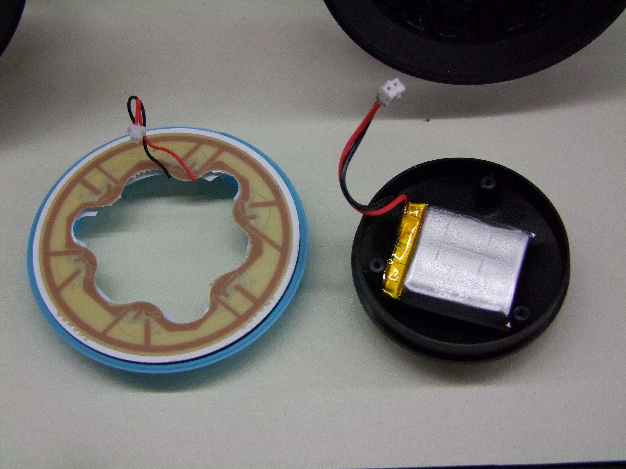
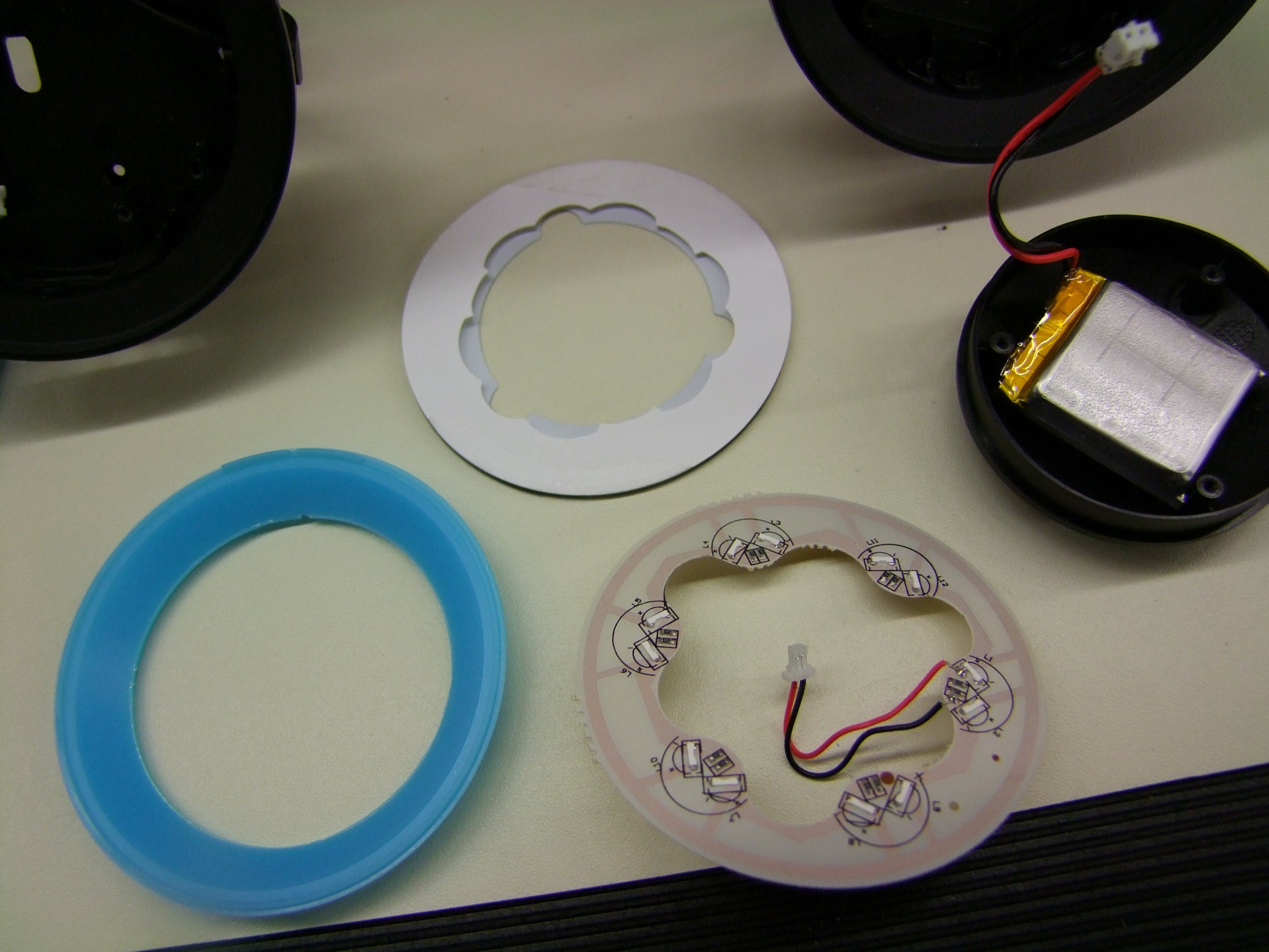
So I had been wondering about the fan – it doesn’t seem to point at anything meaningful, like at the heat sinks. So what’s it trying to cool?

Well, here is the battery in its home orientation. It looks like the fan is supposed to pull air through the battery case – which IS vented, so no IPxx protection for you – and help keep the cells cooler.
So in conclusion, there’s nothing very revolutionary about the battery. It’s reasonably middle of the road technology, well cost optimized, and well packaged. Time will tell if the lack of real battery management circuitry will pose a problem. Let’s move onto the more interesting problem, the chainsaw itself!

I put together the whole unit for fun – clearly, if you are just after the motor, you don’t need to assemble the saw.

The frontmost (righthand) yellow knob locks the chain bar down in place, or it dismounts the whole light-gray cover at the same time unbolting the chain bar, if you untighten it. The winged yellow knob to the left adjusts chain tension by moving the whole bar in and out. This is much the same story as the Ryobi, and seems to be common to chainsaws in general. In fact it seems to be one-better than the Ryobi because instead of tightening two nuts and a small screw to make the tension adjustments, you only handle two very large and visible knobs to make these adjustments. I dunno how helpful that is to chainsaw-monglers in real life, but I LOVE HUGE KNOBS it appears to be a better UI decision.

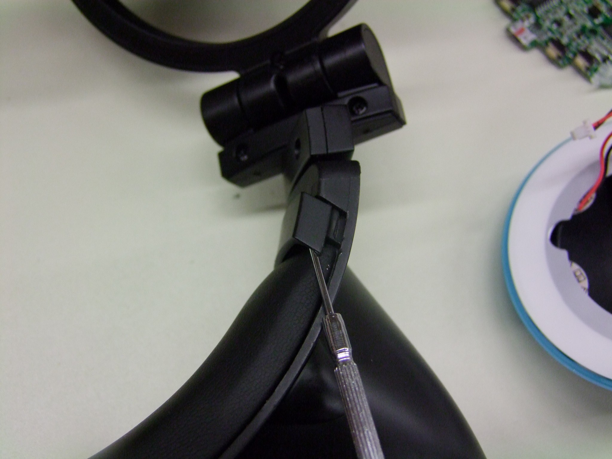
The disassembly begins! T-25 screws hold the handle onto the body. After those come out, the handle is removed. On the back, more T-25 screws hold the motor cover on. I basically began removing every screw in sight on the back side, and the motor cover was the the highest level group of screws. It popped off to reveal:

Okay, this is getting interesting already. We see that the motor is a rather large inrunner-type motor, instead of the outrunner type in the Ryobi. A worm gear-driven oil pump to supply chain oil is tied directly off the rear of the motor shaft. All of these screws holding the pump on can be removed now, to free up maneuvering the motor out later.

By the way, just out of curiosity, I took apart the tension adjustment mechanism, and it is a nifty small crown gear setup.

This crown gear actuates a threaded rod, running longitudinally here, with a nut riding on the end that pulls the bar back and forth.
The next step to disassembly is removing the motor chain sprocket there in the middle. This involves either retaining ring pliers or two small flat-drive screwdrivers and a lot of creative swearing. I used to despise retaining rings in middle and high school before I gained the tools to work with them. Now I love them! Overhaul is basically one big snap ring!

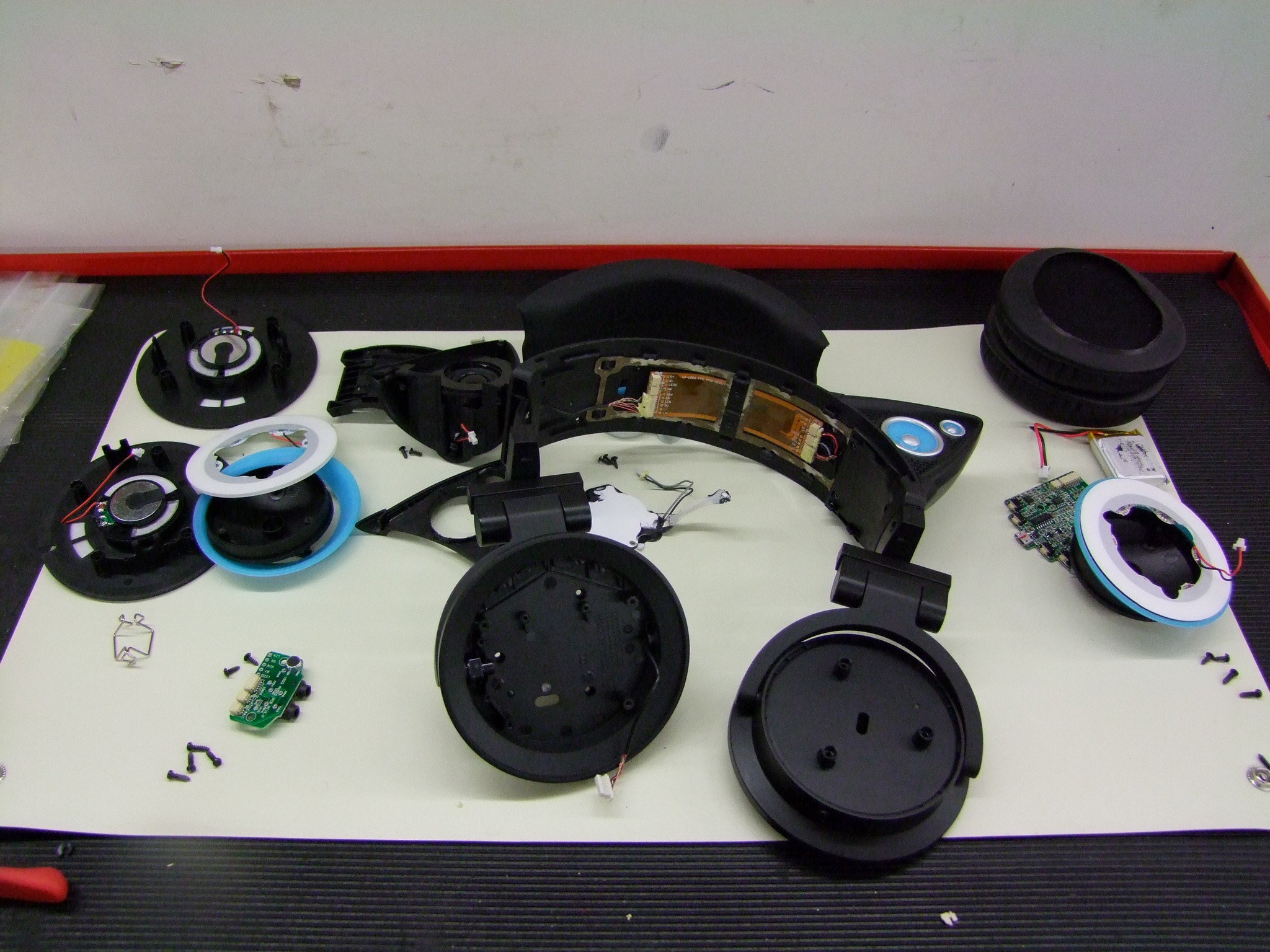
All the T-25 screws on this side pop off, and then the saw basically falls into two halves cleanly.
This thing has a nifty auto-shutoff clutch/brake that is actuated by the big black flap to the upper right. The black flap has to be pulled back for the saw to run. There is a sensing switch that otherwise prevents the motor from being started, as well as a mechanical stop that consists of a pin being spring-loaded into a hub mounted on the motor shaft. This mechanical assembly is shown in the rest state above, where it prevents the motor from turning as well as interlocks the controller.
As I have not actually chainsawed anything in half recently, I figure this is an automatic stop at the end of a cut when your saw falls through the now-cut material. Any small amount of pressure and movement seems to be enough to click the flap back to its home position.

The flap and the motor-stopping pin shown in the working position. Anyone know why this saw has such a feature when the Ryobi didn’t?

The controller is the next easiest thing to slip out, as it just sits in a square cubby. Along with it comes the battery connector and two switches: the trigger switch and the flappy interlock switch.

The clutch parts can be removed as soon as the saw is open.

The motor shroud comes out next after the removal of three small fiberglass-plate retainer clips held in by Phillips head screws.

Finally, some last T25 screws later, the motor can be lifted out.
And here it is. This is actually a huge motor. It physically outsizes the Ryobi motors by at least twice in volume and weight. It has a 12mm double-D-to-10mm-flats shaft, similar to the Ryobi. The big nosecone houses the chain-stop clutch mentione before.
I am utterly surprised at how huge the motor is, and am even more satisfied that it’s found in a $170 NEW saw. This motor is something I’d pay $170 for, period.

The controller, though, needs some more loving. First of all, it’s ON-OFF ONLY in stock form. It ramp-starts the motor up to full speed once both AND-wired (series connected) switchs are closed. When either one is released, it hard-brakes the motor. So hard that the first time it did so, the motor torqued itself out of my hand and chased me around the shop.

I also practically destroyed it freeing it from its potted housing to take a look at the hardware. The architecture is “Classic Jasontroller” as people familiar with my brushless ESC vernacular will understand. It’s built like every e-bike controller I’ve ever seen, in other words. Discrete gate drive circuitry with big and brute force linear regulators.

The MCU is a very typical-Chinese STMicro 8-bit microcontroller, likely a genericized or pin-and-code compatible version available on the Chinese market, even though it has ST markings.
Given that the ESC is “one speed” and basically an e-bike controller, I’m not going to spend much more time talking about it. It’s a known quantity.

And a test video, where my friend forgot the “I’m done with motoring” cue and kept recording for a few awkwardly silent seconds:
So here are the guts of the 63287. My conclusion: It’s an undersized battery and undersized controller for the amount of motor that’s in this thing. Having “one speed” – that’s full speed – compared to the variable speed controller in the Ryobi makes a little more sense now. When the controller is only fully-on and the MOSFETs are not chopping current, there’s less losses to worry about and less heating. That means you can get away with a smaller controller with less semiconductors.
You’d just hope the motor never wants to draw more than 40 amps for a while. That IS a good 1500-1600 watts of cutting, mind you, and through some VERY TERRIFYING locked-rotor testing I discovered the controller does have a stall-protection cutoff feature as wel as a rotor blockage detection on starting. You haven’t lived until this motor has thrown an 8″ Vise-grip at you, but I suppose that’s pretty damn close to dying for something I proclaim to be living-related.
Without further hacking, though, the controller is borderline useless for EV purposes. I could MAYBE see a case for a robot weapon or using it in some other related application like meloncopters for fun, where you’re more likely to be running at full power. However, that battery will not last very long under said full power conditions – 40 amps will drain it in minutes, and if you go over that, you’re likely to blow the fuse up inside.
So I think we see the “Harbory-Freightyness” expressed through some interesting cost-sensitive decisions on the OEM end, such as the lack of a BMS for the battery and no variable speed control. But dat motor – let’s investigate it more.

That is an interesting-ass back-EMF waveform. Hey, this reminds me of my ‘middle finger wave’ days! I can’t even remember what I was building then, but it sure as hell didn’t work.
I spun it with my Milwaukee brushless drill (because my life is brushless) to collect this motor’s intrinsic BEMF profile, a.k.a what the motor really wants you to drive it with. To collect the vernacular “Kv” value – RPMs per volt at no-load, there’s a process involved.
You can take half the peak-to-peak value of this waveform as seen on the oscilloscope and use the relation Vpp/2 [Volts] * delta-T [seconds] / 2π [radians] = Vpp [Volts] * delta-T [seconds] / (4π) [radians] ¹. This yields a value in SI units for the BEMF constant, V*s / rad. Generally, radians are considered unitless so they are not written in unit analyses, but I like to keep them there for less confusion when converting into RPM (rotations per minute, or 2π radians per minute)

For this motor and the measurements shown, the Vpp is 21V and electrical period of the line-to-line voltage is 13.5 milliseconds. This yields a BEMF constant of 0.022 Vs/Rad, which in “Kv” form RPM per Volt is 423.
To get the mechanical RPM of the motor, this basic RPM/V value must be divided by the number of magnetic pole pairs. 423 RPM/V represents what the “unit” 3 phase motor with 2 magnets and 3 phase windings would be. This motor has nine phase windings, but how many magnets does it have?

Three 3mm socket cap screws later and you can very carefully and gingerly work the motor apart. I chose to remove everything from the back side in order to not deal with the mechanical stop hub. The magnetic pull is very powerful and taking the motor down this far is definitely not for the faint of heart or fancier of fingertips.
Counting the magnets reveals there are 6 magnets, or 3 pairs of magnets. Consequently, the RPM/V-as-you-see-it is 423 / 3 [Pole Pairs], yielding 141 RPM/V. As a sanity check, I actually used a tachometer on the motor being driven by the controller, and measured about 6300 RPM on ~40 volts, yielding a value of approximately 157 RPM/V.
This is a slower motor than the Ryobi’s approx. 300 RPM/V. All other parameters being equal, this motor trades speed for torque. Since I don’t chainsaw things reguarly, I’d really be interested to see videos of this saw in competition with others to see what the variation in speed does to affect the cut. But what it means for “other” applications is the need to use less gear ratio for the same output speed and torque, possibly simplifying design.

The motor has a hefty fan on the end and the rotor is reinforced by a stamped steel cup that is also epoxy-bonded to the magnet and the laminated(!) rotor. I think this rotor can survive some overspeed excursions just fine.

Pretty densely packed windings. The airgap diameter of the rotor is exactly 50mm, and the stator lamination unit is 32mm long. I measured the line-to-line resistance as an average of around 39 milliohms. This puts the motor easily in the class of the common 63mm outrunners for power throughput ability. Compare Overhaul’s SK3-6374-149 lift motors at roughly the same Kv and 40-42 milliohms phase resistance; this motor has more iron and copper by mass than the SK3s, so it will be able to hold a certain power dissipation (load) for longer.
Like I said – wow, so much motor for comparatively little everything else! I guess that’s where the money went… everything certainly shows a little for it. I see this product as having a potential future upgrade path with a much larger battery and controller that can push 1.5 to 2x the power into it. That would be chasing after the Greenworks 80V tools in power, I think, having seen a GW 80v chainsaw motor before.
To use this motor well, I think it should be paired with a 150-200A controller to really take advantage of its power capability. It’s not sensored, unlike the Ryobi motor, so that complicates things a little bit – you can’t just throw a Kelly at it, for instance. Maybe BRUSHLESS RAGE a SimonK-flashed large R/C controller or whenever we see a bigger VESC design.
Anyways, is someone interested in a cordless chainsaw without a motor? Contact me. Oh, it’s also taken apart into a billion pieces. Should go back together with a bit of tinkering!


