Every post about Landbearshark ends with the motor controllers exploding

This one is no different. In fact, it will happen twice in this one post. Isn’t that amazing? One of them is due to Sudden Hobbyking Death Syndrome, and the other was most likely caused by laziness-induced idiocy. No, I haven’t fixed Tinytroller yet.

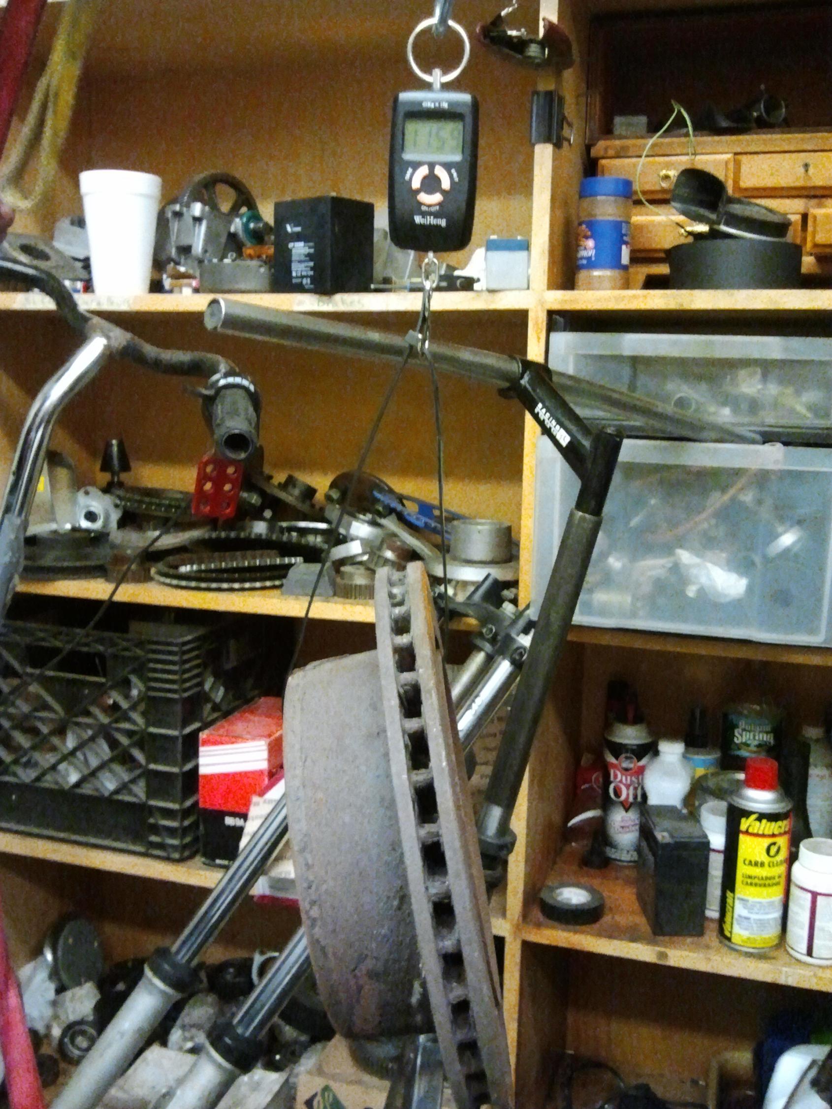
First, I would like to announce that my meterological precognition skills are infallible. On the day after I took apart LBS to install the load cells and wire them in, it snowed!

I swear this has nothing to do with the fact that it was going to snow anyway….seriously. Granted, it was only about 2 inches, but for one reason or another it’s the first two inches of snow this Winter. No, the October one didn’t count. 2 inches is better than asphalt, so I immediately restored LBS to its Last Good Hardware Configuration and we rolled it outside for some successful parking lot rompage. However, it still had its tilty board in this state, which caused the handling to be very unstable especially after water got into the friction washer stack and unfrictioned it.

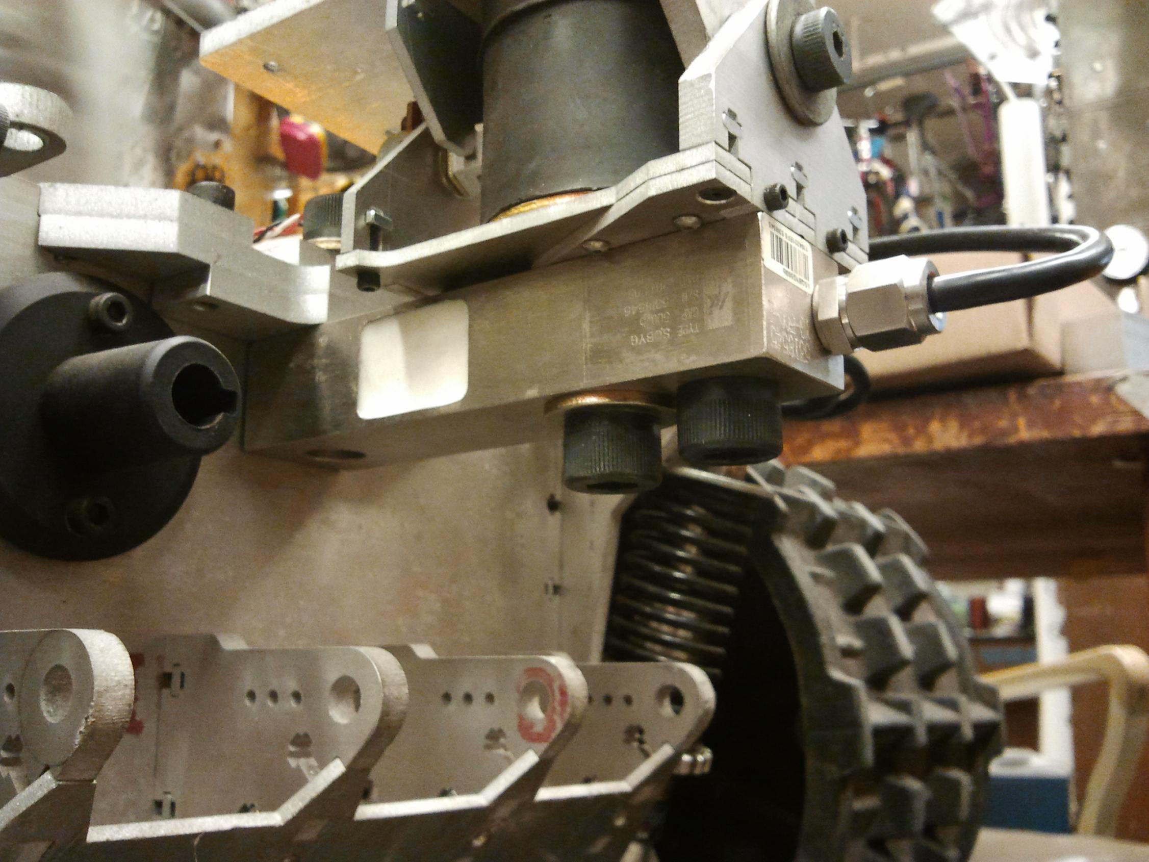
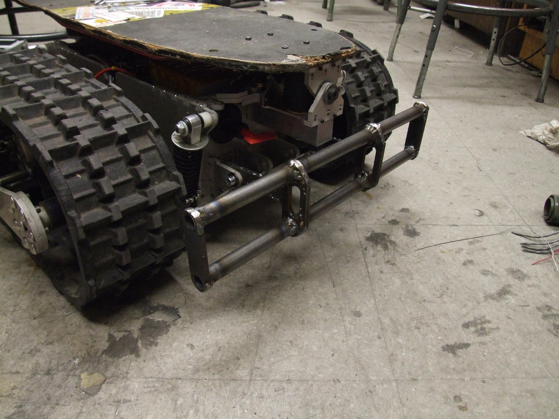
After rolling back in, I decided to lock the board and revert LBS to full R/C once again in preparation for the next round of snow; in other words, the same state as it was for Maker Faire, but slightly more brushless and less reliable. The big rubber bushing was replaced by a chunk of very conveniently sized aluminum round, standoffs from a large chem lab shaker table that was parted out and scrapped. So while the tilty-hinge still technically exists, there’s no way I will physically bend that 1.5″ diameter round.


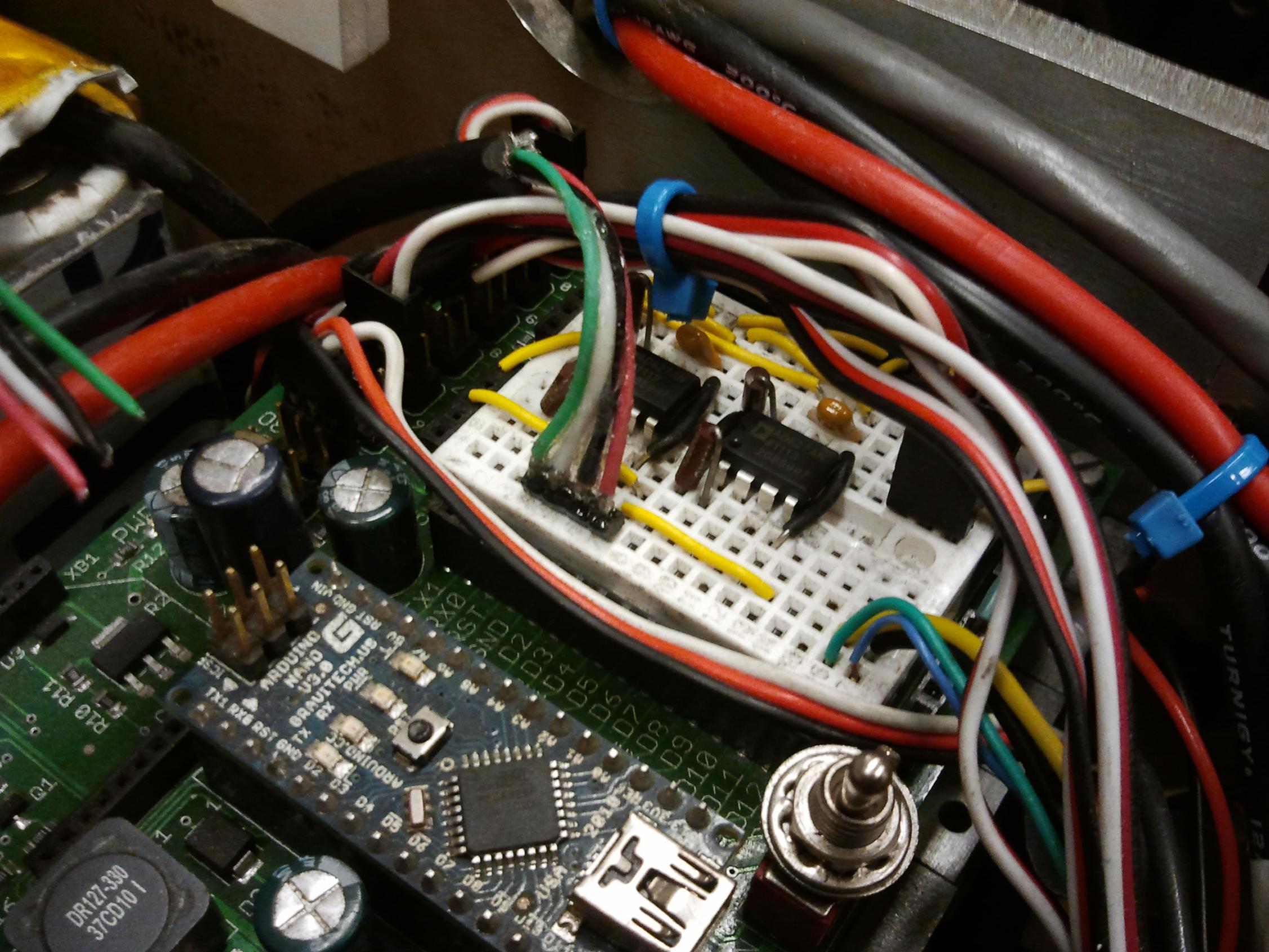
There was another important reason for the reversion to hand control. I wanted to take advantage of the built-in Xbee radio interface on the Nano Carrier to log the load cell readings on my computer as I was riding LBS around. I had suspected that the load cells would pick up any force transmitted through them, including the high frequency rumble of the tracks. The choice of datalogging program was the Arduino UI’s built in Serial monitor, and the number crunching was done in Matlab. After trying a few runs, I found that the board looseness made a clean straight line run nearly impossible. I was aiming to look at only one variable at a time, and the board steering kind of ruined that.

So, back to R/C it was. I elected to try a completely unfiltered (raw readings) run, a run with a 1 second first-order low pass filter on the two load cell readings (done in software), another run with a 0.5 second filter, 0.25s filter, 0.125s filter, etc. The numbers were arbitrary to start with, but geometrically spaced to cover a wide range of values. The tests were done in a straight hallway with a smooth linoleum floor with me standing upright and minimally compensating for vehicle acceleration – i.e. not leaning hard in one direction or the other.

And now, pretty graphs.

AAAAAAAAAAAAHHHHHHHHHHHHHHH

What is that garbage?

During tracks-up testing, I noticed a strange propensity for the op-amp outputs to suddenly go to zero whenever any throttle was applied. The tracks didn’t even have to be moving – if the controllers were trying to power the motor past the stiction of the drivetrain, without actually producing movement, the op amps would rail and then jitter erratically. Keeping in mind these were instrumentation amplifiers with gains of about 300, any millivolts of induced noise could be amplified and picked up by the Arduino. I kept the sensor wiring as far from big power cables as I could, but that made little difference. I’m also fairly confident that I have no strange ungrounded components or missing connections, as the load cell readings are great as long as the motor controllers weren’t powering.

Seems like movement helps the situation a little, but there are still plenty of instances where the readings are just trash, and plenty of places where they’re just zero.  The peak to peak noise during the movement portion of the test is on the order of 25+ kilograms.

Okay, let’s try a really slow filter:

This is a 1 second time constant low pass filter on the data. Hey, that’s starting to look like something now. There’s still spikes and jitter during the movement phase, and it’s very clear that the sensors take a long time to settle. The middle portion of the graph, while a bit spiky, clearly shows me standing mostly level (the readings are similar) That huge spike at the end is me leaning back to compensate for vehicle braking, then jumping off. The fall time of the filter shows a very clear 1 second exponential decay.

Perhaps this is a little too slow to be practical. Let’s try 0.5 seconds:

Oh dear, some of the ground rail strikes and noise is coming back now. The beginning and end show clear signs of me jumping on and jumping back off, and the middle (movement) portion is probably filled with a high percentage of zeros.

And now for the 0.25 second filter:

Unfortunately, the test had to be suspended because one of the 80A HKcartrollers detonated on powerup. I am really not sure what went on here – it was working great literally 5 minutes beforehand and I made no other hardware changes to the system.

My suspicions fall on the left side motor being found to be way out of proper sensor timing range – while I’m not sure on how it happened, it was clear from test running the motor that the sensor ring shifted significantly. This would have caused very high and excessive current draw any time the left track was being run, consequently current-stressing the controller and possibly causing one phase leg to fail short. The next time the power was turned on? Instant pop. Unfortunately, it doesn’t speak very well to the reliability of the cartroller if they can be “plastically deformed” by excessive current. Then again, it’s also risky using a motor which can potentially draw over 400 amps shorted at 18 volts (Those SK motors with an internal resistance of like 30 milliohms) with a controller that has no sense of self-preservation.

Sadness.

Ultimately what I’m seeking isn’t really a clean total weight, but a reliable delta or difference between the front and rear sensors. To that end, I think the measurements are reasonably useful. What I can observe based on the unfiltered readings, though, is that a simple low pass filter is not enough to accurately obtain an estimate of where the rider center of gravity is with the amplifiers in their current noisy and rail-prone states. If I can’t get to the bottom of the amplifier issue, then I will have to implement methods of throwing out data points which are obviously bogus, like the sudden zeroes, or throwing out any data point which is out of some defined bound from the current estimate. Dear god, I might actually need a Kalman filter.

round 2

It was going to snow again yesterday, so I begged a replacement HK Cartroller from jume just to have the thing running again. This time, the goal was to get out there before they started plowing and salting. LBS was kept in load cell, full hand control mode, but I wasn’t really out to take data so much as just diddle in the snow as it was designed to do more than a year ago.

This mission was very successful, as long as I wasn’t on it.

Driving LBS in the snow like that in dumb robot mode totally made me miss building and driving…. robots. I had a small moment there.

Anyways, actual riding performance in the snow was fairly good. It was MUCH better with the board locked – while I was previously not very keen on the idea of using four corner load sensing (so the board is essentially fixed but I can still estimate which way I’m leaning), I’m starting to get the feeling that taking out one degree of freedom in the system will make it easier to ride. Unfortunately, I didn’t get to film the first outside ride run, which went without problems until the left side chain broke.

After compressed-airing off all the snow that had gotten into the frame from doing the riderless snow-donuts (OH GOD MY ARDUINOS) and repairing the left side chain, I took it out for a second run, upon which the other chain promptly jumped off the sprockets, but this time jamming between the rear drive sprocket and the frame. That locked up the motor for a brief instant, but it was enough to toast the other cartroller. Again, the symptom was instantaneous failure on next power cycle.

Very mysterious and a little irritating.

The reason for these chain hops? I neglected to install my tensioners. You know, those little 3d printed donut sprockets that I’ve had on LBS since forever, but removed for this drivetrain version because the tension was “just right”. All chains loosen slightly once they wear in the rough forged and machined surfaces on their pins and rollers, a fact that I actively neglected.  Also, my main drive sprocket is not chamfered like all normal sprockets should be. This makes them extra-vulnerable to very slightly axial movement of the chain. I don’t want to take the drivetrain apart again, so I might do an in-place chamfer grind with a Dremel or something.

I did remount the chain tensioners after bringing LBS back inside, but now i’m out of cartrollers. I am also not sure if I want to keep replacing them – like most hobby parts, they seem to work great if not run near their maximum capacity on a system which cannot damage them through current spikes… which a 63mm aircraft motor definitely will do very easily.

While I hate to think about it, going back to Kelly KBS controllers is very tempting. They have torque control, current limiting, variable braking, and reverse… and have been running Tinykart quite well once the motor sensor timing was dialed in – something the original C80/85 “short melons” were not treated with. As I discovered when trying them with Tinytroller, the sensors as-installed were practically useless.

Going back to Kellys would mean I can run at 36+ volts again, and I can rewind the SK motors to optimize their torque production for that range, and… Hey, isn’t doing that just going full circle? Maybe I should just use some short magmotors and a Vantec RDFR36E just like an old school Battlebot. Or, go back to the CIM motors and use Victors, like a FIRST robot. I should just keep this thing as a robot and pile 200 pounds of steel on top of it to give it more traction.

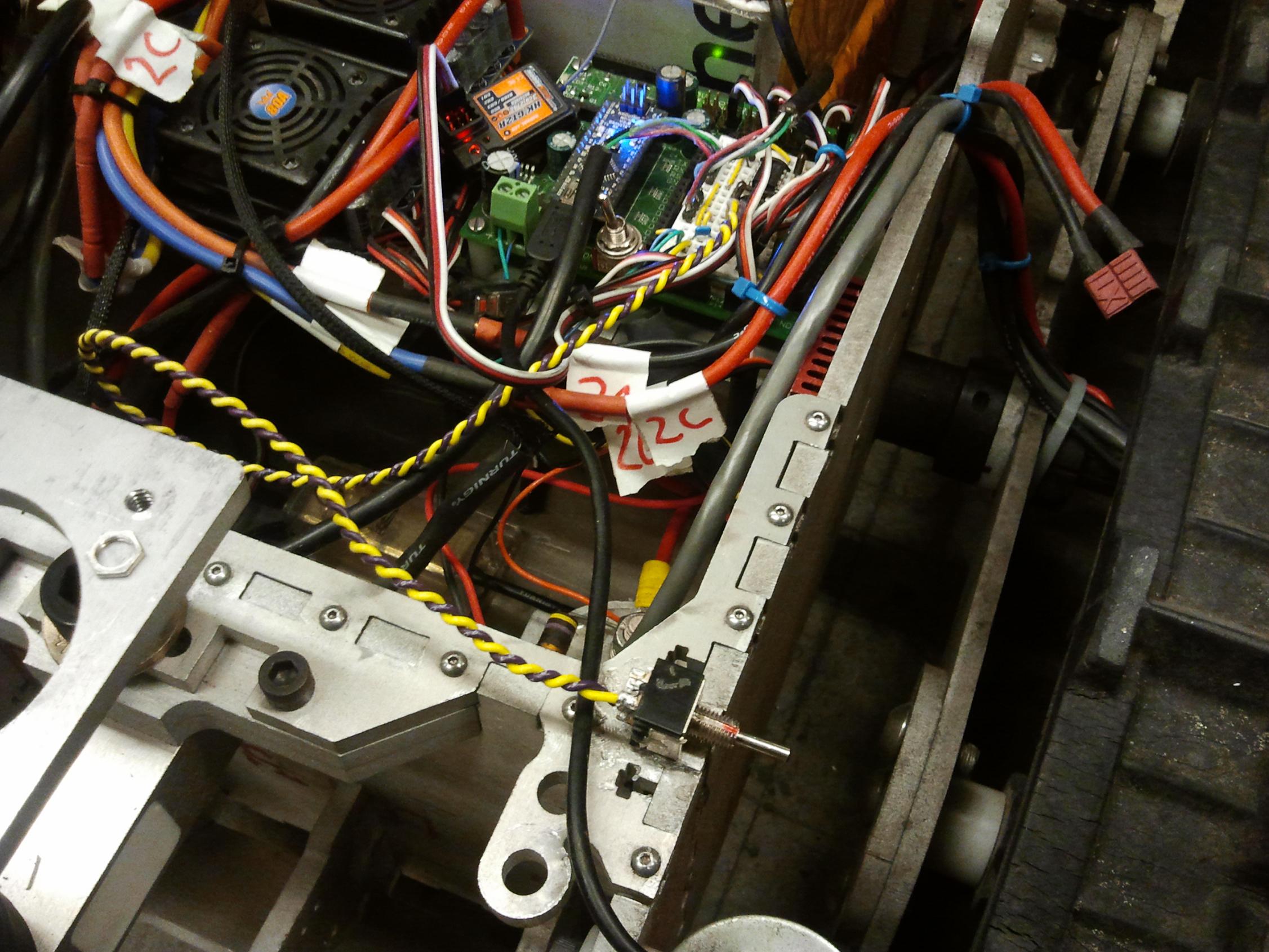
Oh yeah, here’s what an exploded HK cartroller board looks like:

For the record, they emit pink smoke!

Most Elaborate Bathroom Scale Ever

In another episode of “Charles digs out old and semi-abandoned projects to work on them because he currently can’t afford to work on new ones“, I spent a day fitting the Landbearshark with front and rear load cells in the interest of converting it to fully hands-free operation. I’ve gotten it to the point where I have created a noisy and metrologically unsound bathroom scale, finding out just how fat I am.

A few months ago, I redesigned the pivot mount for the skateboard to include provisions for mounting a cantilever load cell on either end. I actually received the load cells a few days after finishing the new hinge and trying the hands-free steering, but just stuffed them away for the time being to focus on other things, such as Tinytroller and…. what the hell else did I do this fall? I also didn’t want to take LBS apart again and have it in a non-working state as the winter approached, since I figured any snow day romping was better than none, hands-free or otherwise.

The problem is, it seems that by virtue of being fully functional, LBS has delayed or neutralized the winter snowfall. For the past few weeks, it’s been either

  • Mid 40s and 50s, like spring or late fall, and raining really heavily, or
  • Single digits temperatures, clear and windy. Really, really windy.

If it’s going to be this cold and depressing, I’m going to move back South, where they have nicer 3d printers.

Either way, I’m making it official that LBS is not in a working state right now due to the load cell experimentations. There. It should start snowing tomorrow, right?

The load cells are 500lb capacity bricks of steel that I selected through extensive eBay research (read: “Price + Shipping: Lowest First”)  made by Keli Electric. I decided to royally overspec them because the flexure sections of these beams were to be the only mechanical link between the board and the rest of the frame, with no hard stop to take up overloads past the maximum load deformation. In a better constrained application, they’d be really overkill for sure.

They came with little certification sheets that seem to be standard to all load cells, including specifications such as sensitivity in millivolts of output per volt of excitation (at full scale measurement), input and output impedances, linearity tolerances, etc.

They also have quality control stamps on them, presumably meaning “Yeah, it’s shaped correctly and has the right number of wires coming out of it”. There’s still something about Chinese QC stickers that makes my inner Chinese migrant worker tingle a little.

Because my pretend-o-cells were made to the same dimensions as the real thing (or vice versa), they dropped in place quickly. The only difference is that they were 1″ thick instead of 1.25″, which warranted shaving 1/4″ off the bolt lengths on the lathe.

I whipped up a quick dual amplifier circuit using some AD627 instrumentation op amps from Anabork Devices. These things are expensive. Not the most expensive op-amp I’ve had the joy of playing with, but I had to buy them myself this time. I chose to do that instead of trying to put together multiple discrete op amps into a differential-input, instrumentation amplifier config because of the limited space on this breadboard and the fact that prepackaged amps allowed me to change the gain with only a single resistor. Breadboard on a vehicle. Bad idea? Yes. Convenient? Hell yes.

With 5 volts of excitation and 3 (+/- a bit) millivolts per volt, I was looking at only 15mV at 500 pounds full scale. I wanted to bring that to a full 5 volts of swing for mathematical convenience, necessitating a gain of 333 or so. Using the only 1% precision resistors I could locate at the time, which was 2 301 ohm resistors in series, I can get a gain of about 337. That’s like 333, right?

All the math in the world doesn’t prevent physical systems from behaving nonideally or me from being lazy and taking shortcuts. Therefore, I wanted each load cell calibrated with a known mass. I selected this 11.6 kilogram truck disc brake found in a corner of MITERS (placing pretty high in the “Weird shit found in MITERS” contest, actually) as the calibration mass. To find the actual mass of the thing, I used a cheap hanging digital scale.

Calibrating one shady Chinese scale with another shady Chinese scale. This is the pinnacle of Instrumentation and Measurement achievement.

The actual gains found were slightly higher at 334 and 352, +/- a MIT Mechanical Engineering degree or two. Each load cell also had a “zero reading” that was subtracted beforehand.

After calibration, I determined my internal ADC-LSB-to-kilograms-mass conversion was about 4.5. This is not going to be a very precise scale, but I’m not trying to measure weight down to the millinewton anyway. The shifting of weight is what will be controlling the vehicle in the end.

When I started writing the load cell reading-averaging code, I decided to include a “zero” function which pauses the entire vehicle operation, takes several measurements (namely 32, spaced 10 milliseconds apart) of the load cells, averages them, then saves the result to EEPROM to use as a new zero on the next power cycle. This was done because I did not, and could not assume, the final weight of the skateboard in order to hard code in a zero. The idea is that this would only be done once or twice after everything’s mounted, and not on every power cycle.

I had to figure out how to split a 16 bit integer (the output of the ADC from reading the load cell) into two bytes in order to stuff it into the atmega328’s EEPROM sector. I crosschecked my result with the Internets, and… hey, I diditrite.

Reading:

  //eeprom 10: low byte, front zero
  //eeprom 11: high byte, front zero
  //etc
  front_lc_zero = EEPROM.read(10);
  front_lc_zero += 255 * EEPROM.read(11);
  rear_lc_zero = EEPROM.read(12);
  rear_lc_zero += 255 * EEPROM.read(13);

(The 255 multiplication is equivalent to left shifting by 8 bits anyway – I was lazy).

front_lc_zero et. al. are unsigned integers. Essentially the “high byte” of a 16 bit long number is the low byte but multiplied by 255, or left-shifted by 8 bits. Hence, first populate the variable with the directly-read low byte, then add the future high byte, but shift it leftward past the existing 8 low bits.

And writing:

    fznew_lowbyte = ( front_zero_new & 0xff);
    fznew_highbyte = ( (front_zero_new >> 8) & 0xff);
    EEPROM.write(10,fznew_lowbyte);
    EEPROM.write(11,fznew_highbyte);

    rznew_lowbyte = ( rear_zero_new & 0xff);
    rznew_highbyte = ( (rear_zero_new >> 8) & 0xFF);
    EEPROM.write(12,rznew_lowbyte);
    EEPROM.write(13,rznew_highbyte);

where fznew and rznew were the zeroing averages, 16 bit numbers.

This took me much longer to figure out. The first operation (front_zero_new & 0xff) performs a bitwise AND between front_zero_new and the hex number 0xff, which when expanded to 16 bits is the binary sequence 0000000011111111 (or 0x00ff). It has the effect of cutting off the high byte of front_zero_new, leaving just one byte (the lower 8 bits). This byte is written to memory.

The second operation saves the high byte by just shifting right 8 bits (or dividing by 255, integer). The existing lower 8 bits are right shifted out of existence. The upper byte becomes the new lower byte, and this temporary representation is saved to memory. I didn’t have the second “& 0xff” at first, and it seemed to work just fine, but apparently it is good practice to apply the ‘bit mask’ anyway just to make sure nothing remains in the former high byte.

I used Arduino’s built-in EEPROM library to do this, so it probably did many horrible things to my carefully crafted inputs, but the results are legit. The happy zero point of my load cells, with the skateboard installed, seems to be about 623/1023 (Front) and 628/1023 (rear), in ADC least significant bits.

ui design

At this point, with the ability to read and save two load cell readings and roughly determine where my weight is concentrated, the problem has progressed to user interface design. I anticipate first trying a naive, absolute weight shift (difference between front and rear readings) kind of throttle control, but ultimately I want to create on that is adaptative to user weight and normalizes the throttle response with respect to it.

So, ideally it would be ratiometric. For instance, having 75% of your weight on the front half of the board (75/25) would be full forward throttle, and vice versa – example numbers only. I’d have to be able to keep track of total weight and filter out any gravitational effects – even bending my knees while standing on the load sensors affected the reading significantly. The total weight reading would probably be heavily filtered with a time constant of several seconds (if not longer, like a minute) such that it adapts over time but is immune to rattling and brief gravitational transients. An accelerometer might be useful in cancelling the effect.

Otherwise, the usual problem of making the command a speed/throttle % setting or a ramp (throttle % increment per second) will also need resolving. I seem to prefer the former, but quite a few people who ride LBS seem to like it slowly ramping up and down. Under the latter system, to keep increasing speed, you’d keep leaning forward, and vice versa.

Oh – speaking of rattling, the track rumble along the ground epicly destroys the clean static readings. I’m going to have to come up with some clever software hack around that – possibly as simple as a long time constant filter (1 second or so) for each load cell, but it may progress to more elaborate solutions like adaptive bandstop filters that center directly on the track rumble frequency as a function of motor speed and…

I just opened a refrigerated trailer full of boxes of cans of software worms, didn’t I? Let’s do something mechanical:

I decided that LBS would look much better with a huge crash bar on the front.

It’s not entirely decorative, however: these assemblies protect the load cells from taking direct impacts if I run into something, fall off, or wheelie/stoppie. There is a complementary but smaller assembly that goes on the back, which I have yet to gorilla weld up.

But doesn’t that look badass?