In the last RazEr episode, I whipped up the mechanical design for the monster truck wheel that will be the new scooter motor.The giant ass-magnets came in last week, as did the aluminum pipe that I purchased for the can, and the new bearings from my favorite shady eBay bearing house. So now, I’m going to build it.
Additionally, with the advent of the DEC modules and the chance to start completely from scratch (as opposed to rebuilding the old RazEr motor over and over), there is one experiment that I have been meaning to try on a motor like this. But first, some pictures.

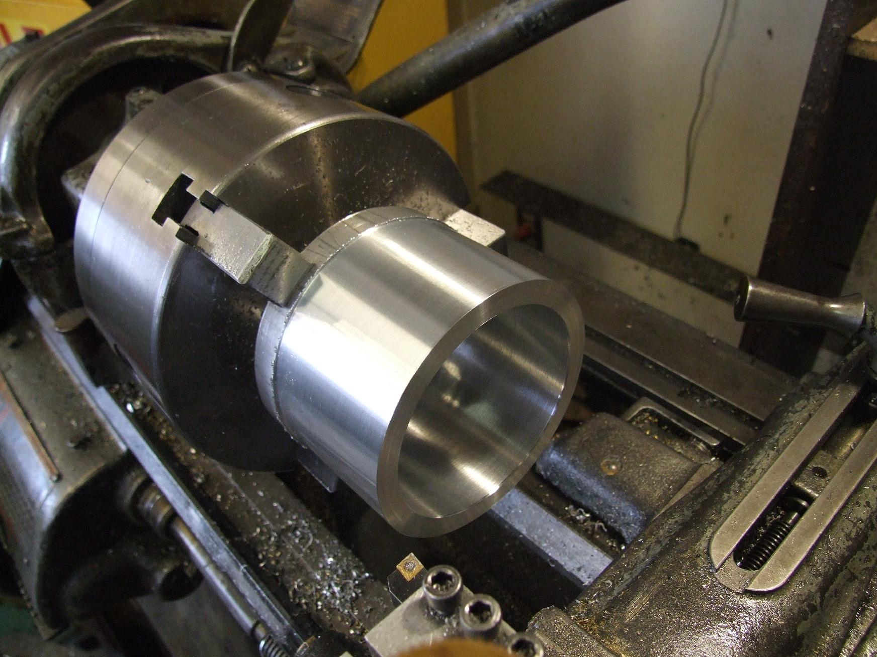
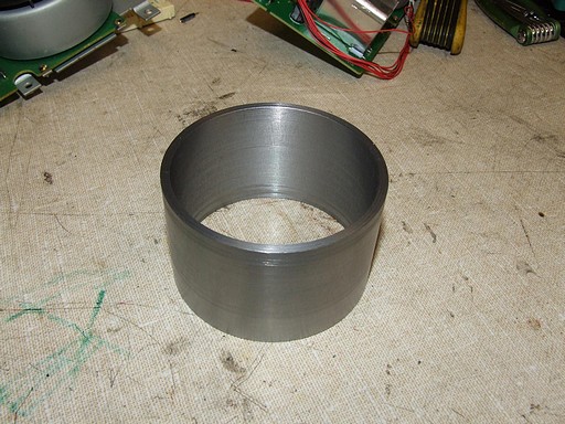
The can of the motor will be made from a 4″ OD, 1/2″ wall aluminum tube. Here, I’m turning and boring the can to bounding dimensions on the Old Mercedes. Boring this thing out was an entertaining process, since the longest boring cutter I had only cut to 2.25″ depth, and the motor tube interior had to be a minimum of 2.8″ deep. As such, I had to hang the bit way out for extra depth and angle it counterclockwise slightly so the tube wouldn’t hit the shank. This resulted in a plenum of squeeeeeeeeeeeeeeeeeeeeeeeeeal that probably lost everyone in MITERS at the time a few years of audial health.

Luckily, the finishing pass on the bore cleaned out all the chatter, and the resulting can is the single shiniest thing I have ever made at MITERS. I adore fresh carbide inserts.
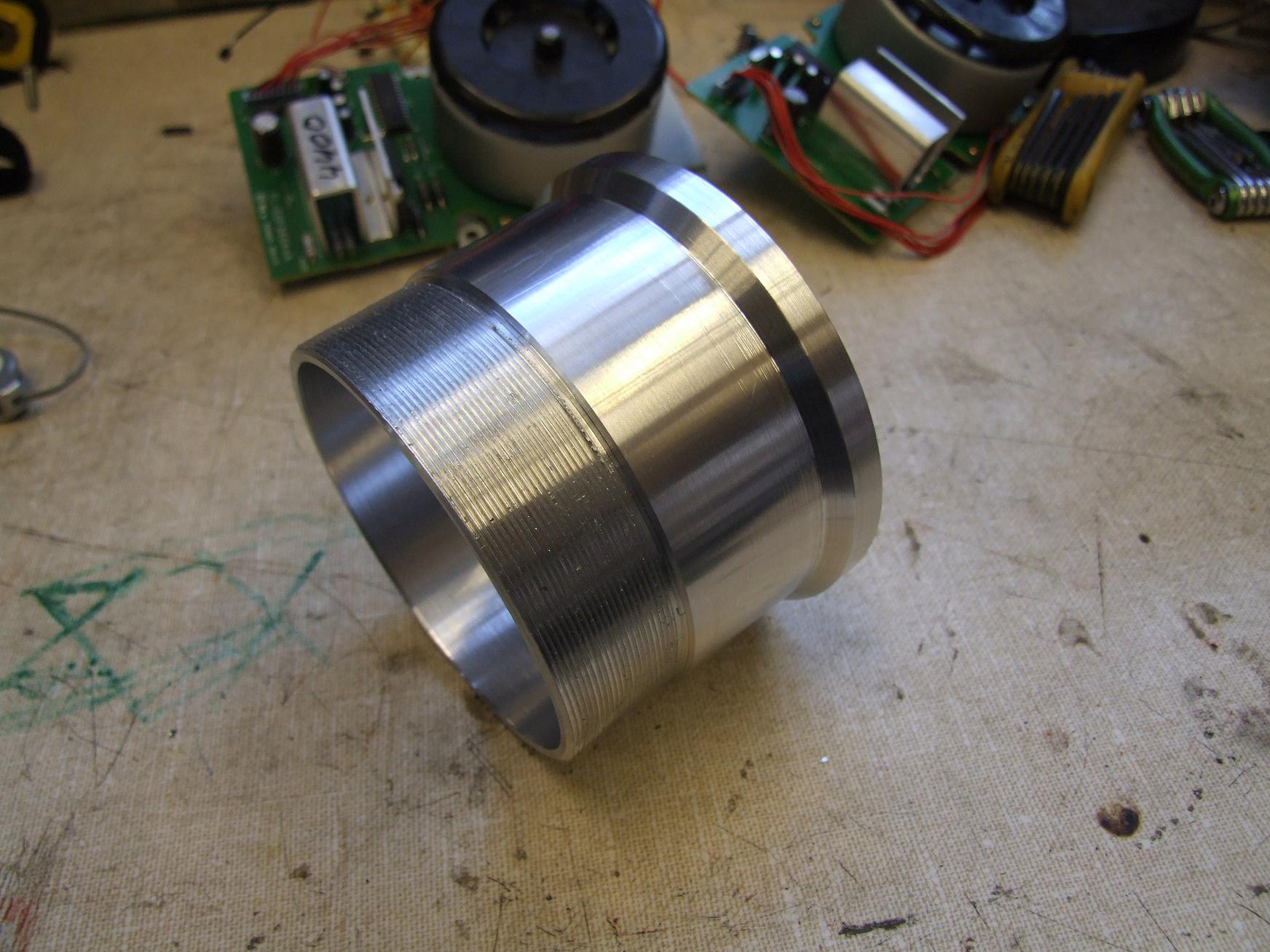
The tube handled threading very well, which was surprising, but is probably a result of the large diameter. The thread itself is a 3.5″-24 thread, which isn’t any sort of standard as far as I can tell.
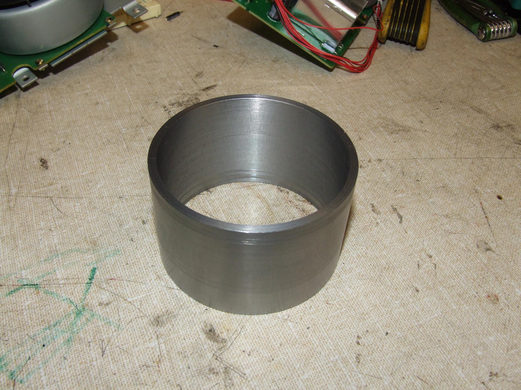
For the magnet can, I decided to save the trouble of machining a long steel part on our machine, and instead tripped over to the heävy \m/etäl machine in the automotive shop. Yes, the same one I was trimming down little plastic propellers with. While I’m generally not a fan of the larger lathe because of its impersonal feel and lack of cross slide locks, there are some times when there is no substitute for several tons of cast iron – namely, when you’re deep-boring in steel like I was with the motor cans. There was absolutely no chatter, skipping, or unsteadiness whatsoever.
I finished the inner diameter slightly larger than designed to loosen the very optimistic air gap of 0.3 millimeters.
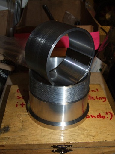
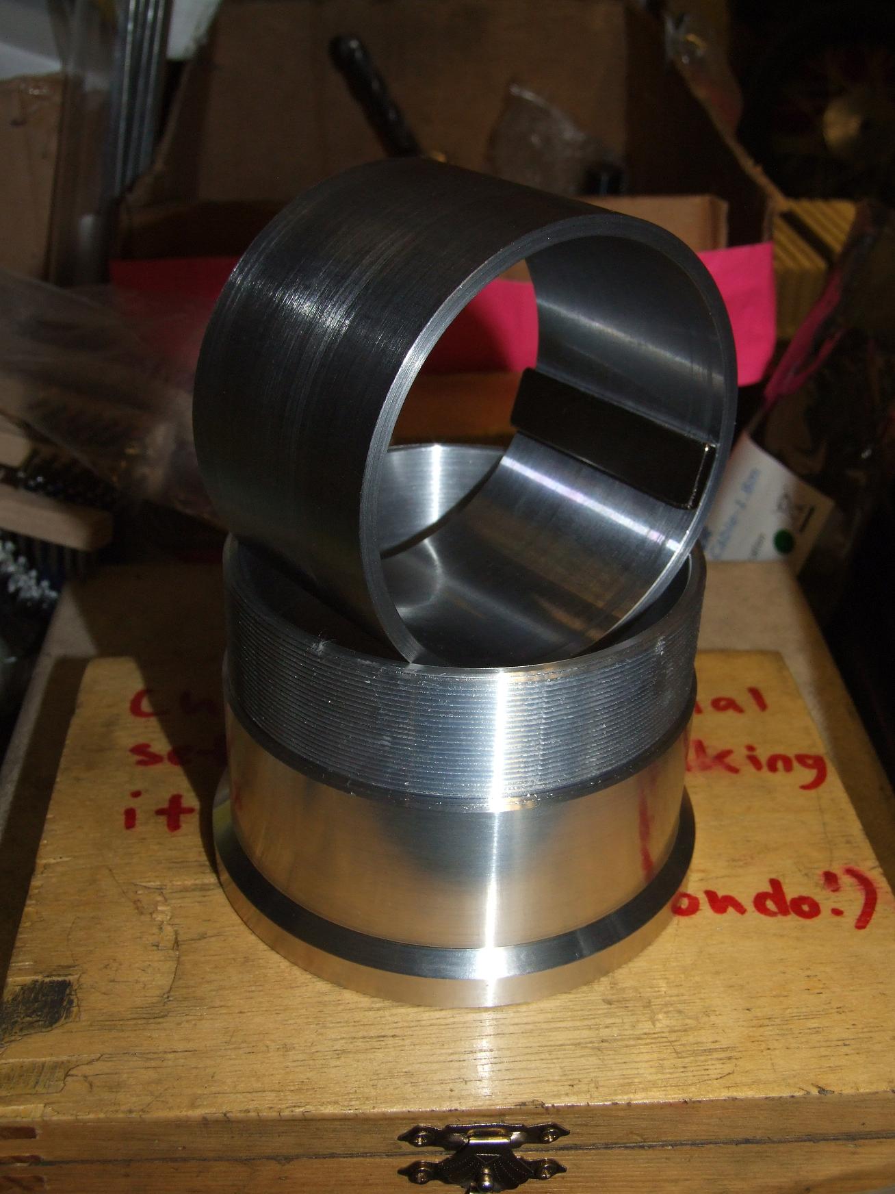
Complementary shinies. The magnet can will be pressed into the aluminum outer shell after the magnets are installed.
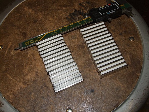
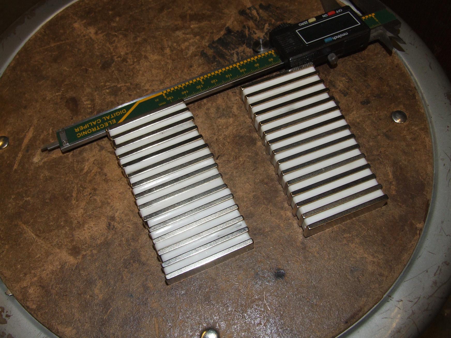
Speaking of the magnets, here they are. 2″ long, 1/8″ thick, and 1/2″ wide. I purchased enough for two motors just in case I ever want to make RazErWD.

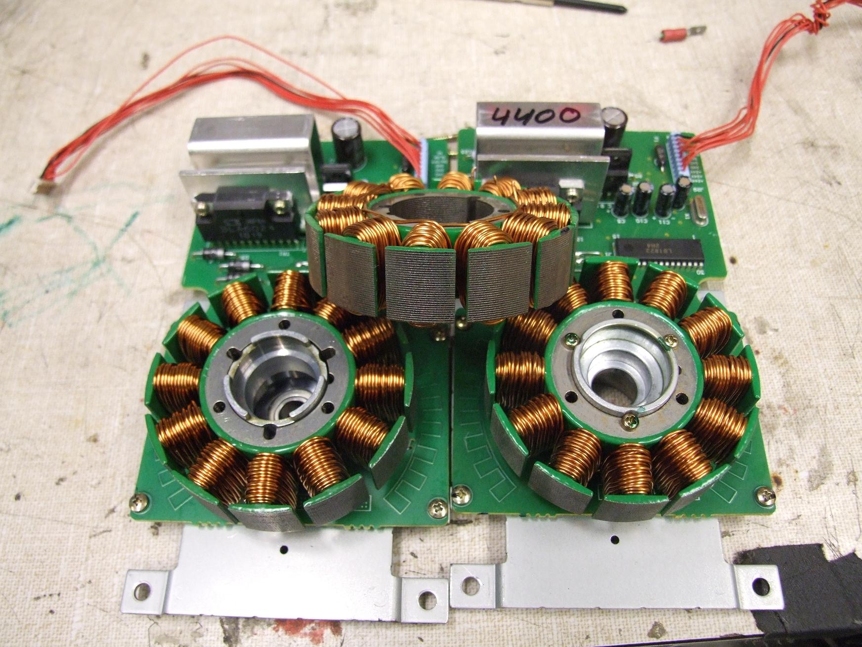
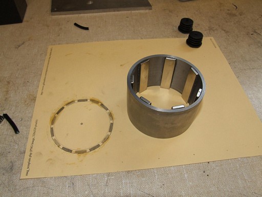
After finishing the major machining, I began harvesting the stators out of the copier motors. These are motors from a Xerox Phaser 4400 laser printer (Okay, so it’s technically not a copier motor, but copiers have this stuff too) that I snatched off Ebay in a sleep-induced motor binge.
These motors come apart reasonably easily – the can comes off after the front retaining ring is removed, then the stators just unscrews from its mounting post. So convenient compared to the pressed-and-Loc’dtite motors that I’ve had to deal with for RazEr in the past.

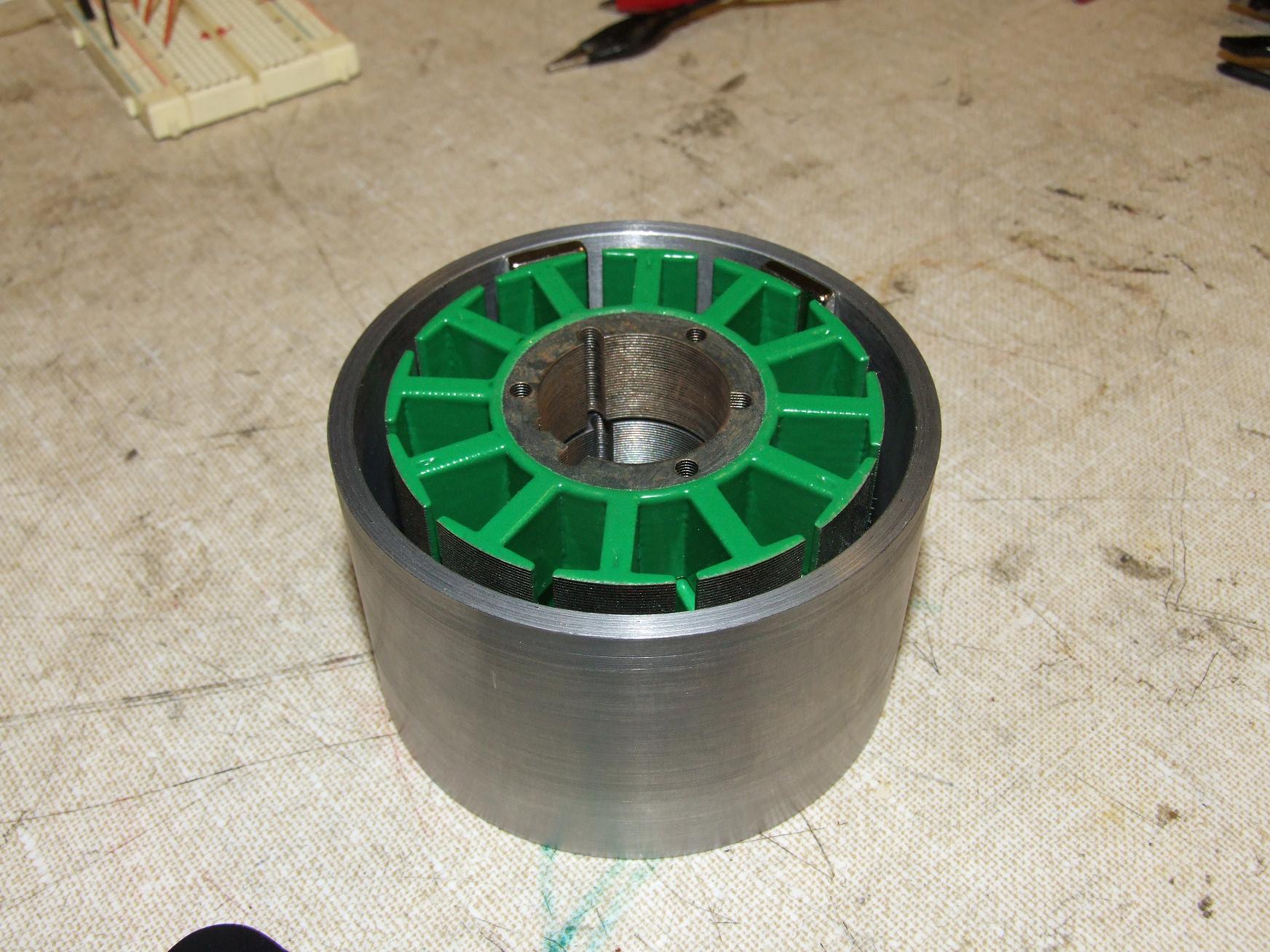
Cleaning the carcasses was easy, if not a bit repetitive. Here, I’ve lined them up inside the can to check for basic clearances.
And now the magnet gluing process begins. Again, I printed out the Handy Dandy Gobrushless Magnet Placement Guide. The seven magnets in there now are all the same pole orientation – they’re far enough away such that they do not affect each other, so epoxying them all down was easy.
MITERS received a shipment of legit extra-long set fiberglass lamination epoxy, so it meant that I didn’t have to deal with my adhesives setting on me as I was trying to maneuver the magnets in place. RazErmotors of the past have just used cheap hardware store hour-epoxy, or even worse, 5 minute epoxy.
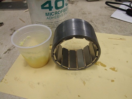
After leaving these placeholder magnets to bake for a day, I returned to fill in the opposite pole. I found some +14 Balsa Wood Strips of Convenience that tucked tight into the gaps between the magnets. This was absolutely phenomenal, since that meant I didn’t have to play the (here physically impossible) game of inter-magnet balancing.
I found some glass epoxy filler hiding in the chemical supply shelf, so I mixed some of it up for placing the last magnets. I also filled all the gaps and edges with the stuff, so hopefully this can is much more structural than ones I’ve made in the past.
dual interleaved razermotor
The whole reason why I titled this post. I’m actually going to make two essentially independent motors inside this one motor. Why? Because I have enough volume inside the monster truck tire to put two motors, duh.
Well, that and the fact that the motor architecture is amenable to such modifications. The end result should let me push 4 times the amount of power I could otherwise flow through the windings, with the added bonus of double redundancy.
The average 12-tooth 14-pole LRK motor is generally wound in a “skip-tooth” configuration. Below is a diagram of a typical LRK winding (from the Crazy German R/C Aircraft Guy of all CGRAGs) and what a motor wound like this actually looks like (from the BWD scooter, again).


I have historically wound my motors in the “distributed LRK” style, which spreads the single winding out to two adjacent teeth, with coils facing opposite directions. This is diagrammed out on the same site. The first observation that can be made is that the two (or four, if you count the other side of the motor) windings have different chiralities. This is something that has bitten me in the ass before.
The LRK winding in conventional Crazy International R/C Airplane Guy notation is A-b-C-a-B-c where the dashes indicate unwound teeth. The dLRK winding is AabBCcaABbcC. If you look carefully, there’s two full conventional LRK motors hidden in the winding, facing opposite directions.
- AabBCcaABbcC
- AabBCcaABbcC
Therefore, the second observation is that two interleaved motors can be wound on the same stator. Optimally, they would share the same Hall sensor commutation points, which are identical to that of a straight dLRK motor.
The consequences of this dual motor setup should be four times the maximum power of said standard dLRK motor. This is because each winding will be half the length, produce half the back-EMF, yet have half the phase resistance. Twice the current can flow, but the torque constant will be halved, and there are also twice as many windings now. However, because the back-EMF is also halved, the motor will tend to spin twice as fast.
Roughly speaking.
To effect these ends into the new RazEr motor, I have prepared the “RazEr Double DEC’er” board, a variant of the skate controller boards that I specially bred (designed) to fit into the available space in the scooter, which is more square.
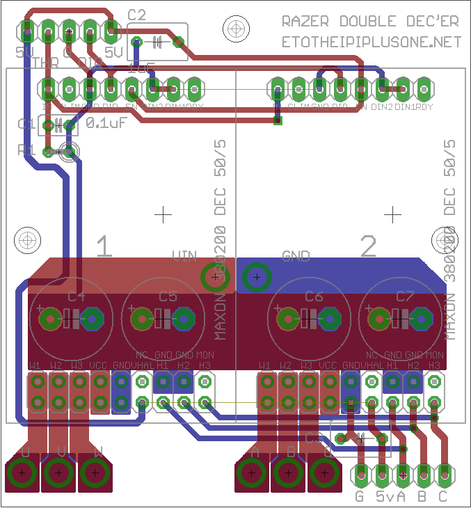
Notice how the Hall sensor inputs are common to both DECs, as is the throttle and other signal pins.
I actually designed these boards a while back (before DIR became a legitimate idea of its own, and when I was just seeking to make a 2WD scooter), but with the above modifications made so the DECs are chained to eachother, I sent the boards to be fabbed.
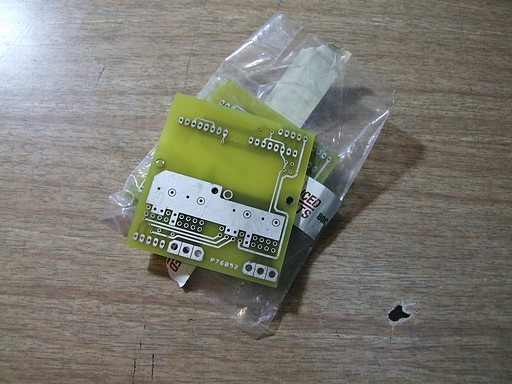
…Yeah, I was a cheapskate again and went with the unmasked, unscreened board option. Hey, at least they conduct in the places they should.
Steps left on RazEr rEVolution:
- Finish making the motor! I need to machine the center axle & stator mount, then fit the stator. The endcaps also need to be machined.
- Cut the frame pieces once I get my aluminom slabs in.
- Wind the motor with the dual interleaved LRK winding (which will most likely fuck with my mind at least once).
- Assemble the RDD board and see if my crazy idea actually works
- SCOOTER PARTY