Cold Arbor is now at a stage of completion where if necessary I can rig everything else together in 30 minutes. By this, I mean that the only thing missing from the bot is a means to control the DC saw motor. Interestingly enough, I’m well-stocked when it comes to brushless DC controllers, but now I want a single-direction 24 volt brushed ESC and that’s apparently asking a little too much.
The past few days have been filled with intensive Arbor work. After recutting and remaking the front sheet metal assembly, the rest of the robot came together quickly; as did the wiring. I’ve driven the sawless base around using the Hobbyking radios, and have pretty much confirmed their legitimacy for myself. It’s also just as fast and squirrelly as I remember it being.
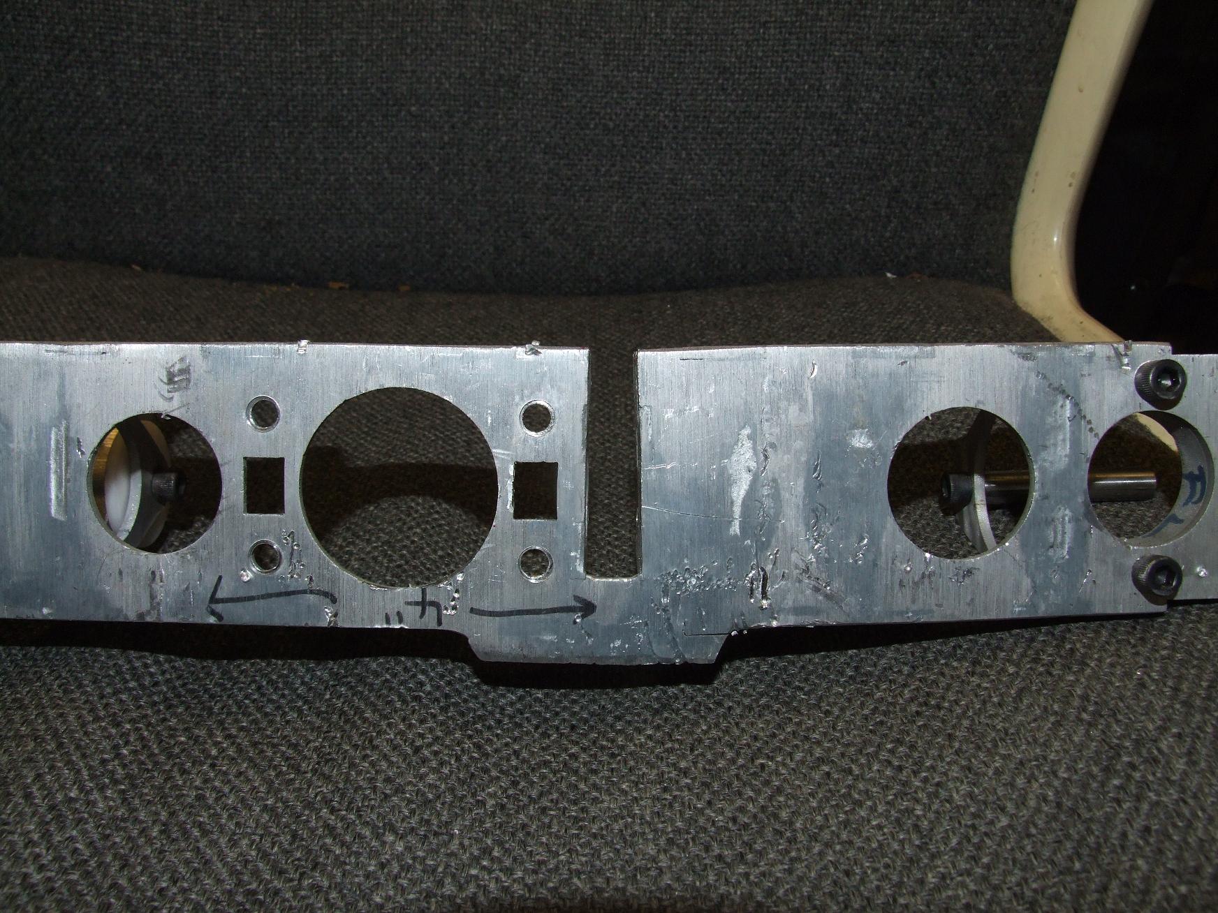
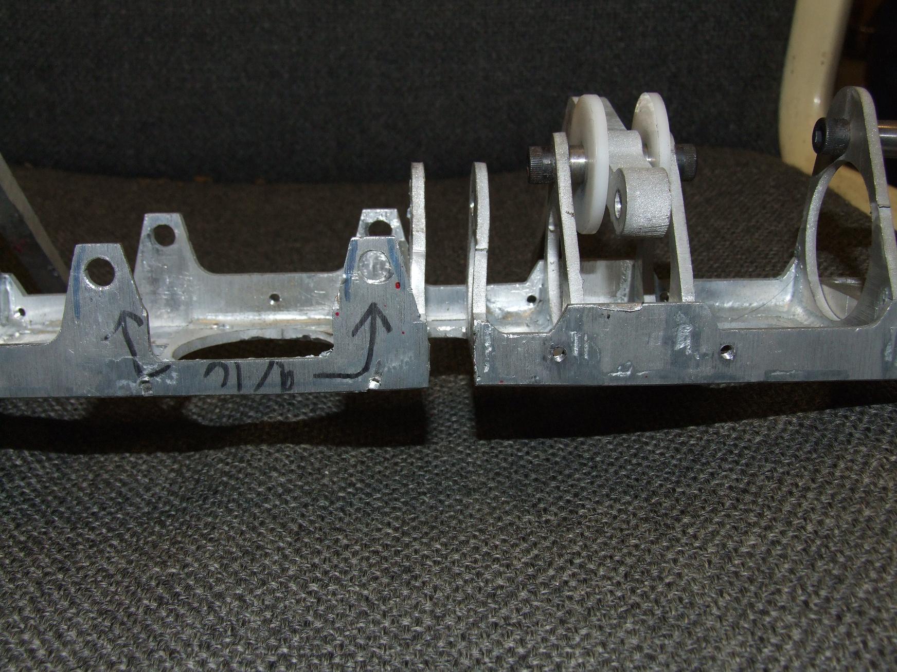
The updated sheet metal work strengthens the area around the Slot of Saw Clearing (+1). The drop down flange extends farther in both directions from the slot, and more importantly, envelops the tabbing on the top and bottom flanges. I’ve also gotten rid of the ridiculous holes in the mounting ears that stick out backwards.
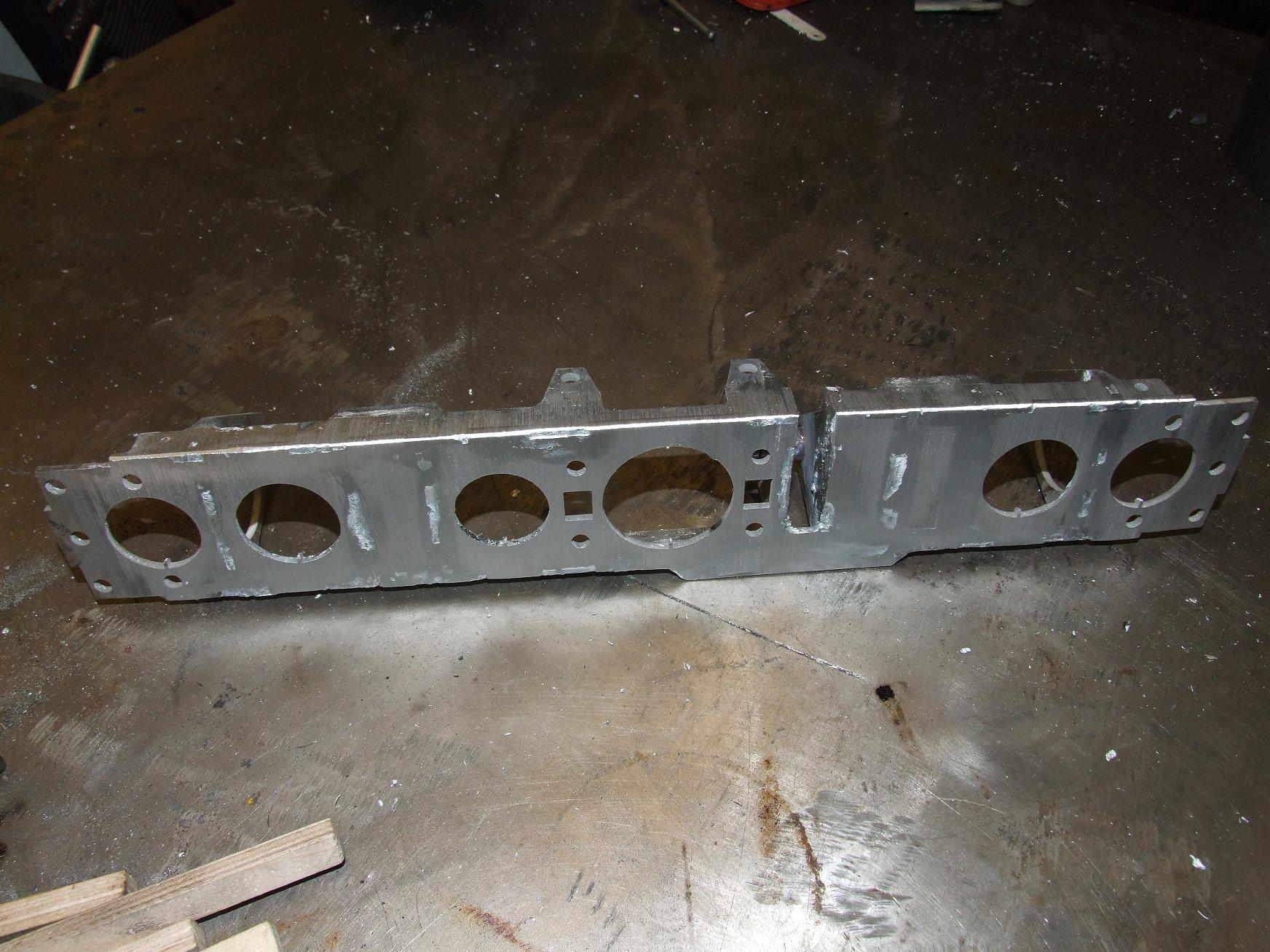
The whole show was, again, assembled using the weird aluminum-zinc solder-braze-weld alloy, then cleaned up on the belt sander.
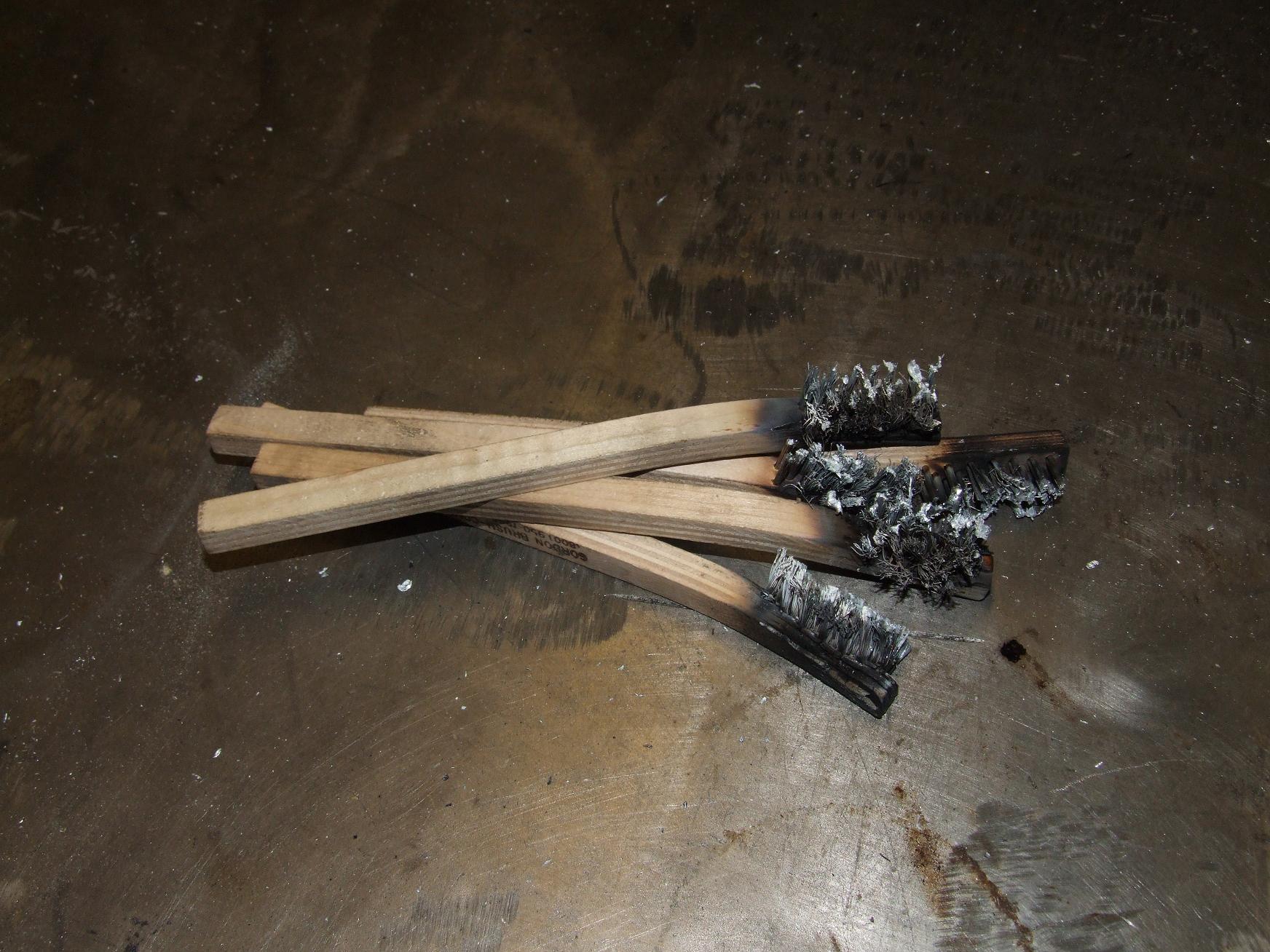
The casualty rate for this piece was unusually high since I brushed the alloy in with far more pressure than I usually do. I’m hoping this will make for better adhesion.
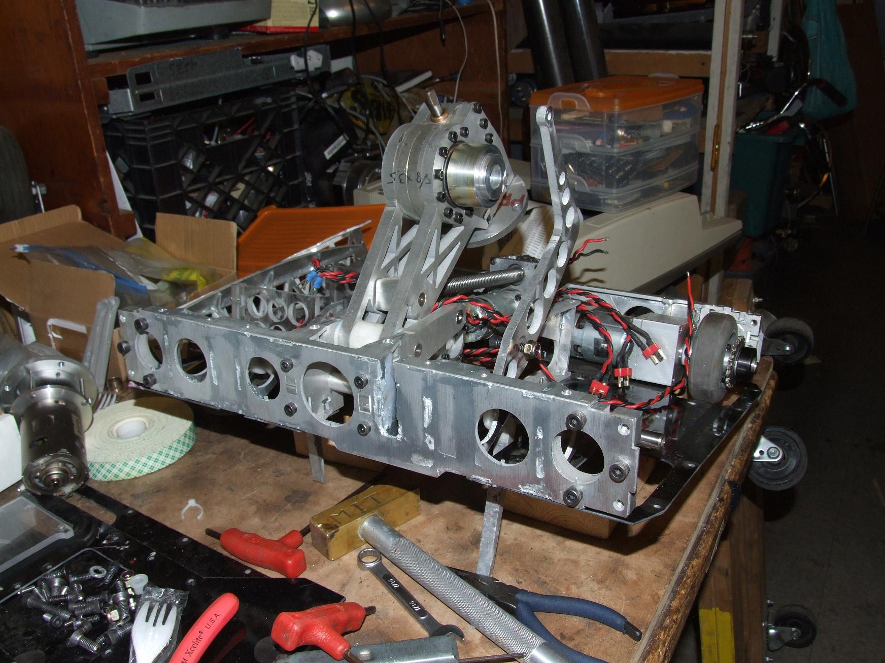
After everything cooled down from the operations, I began remounting the saw. Arbor is assembled in a very linear, single-track fashion. In order to get the front off, all the sides had to come off first.
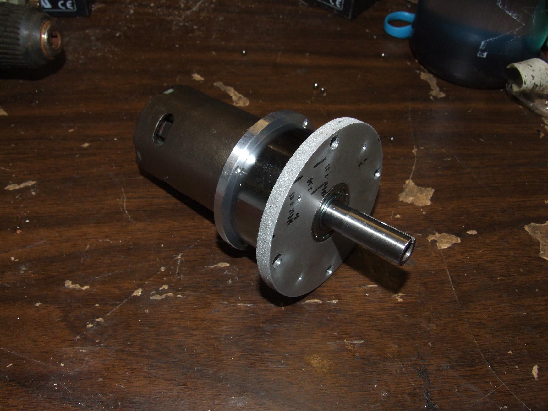
Also, in order to replace a motor, I have to use 3 different sizes of hex wrench on 4 sides of the robot at once. Once the saw arm assembly was refixed, I went ahead with steps to mount the Preduction.
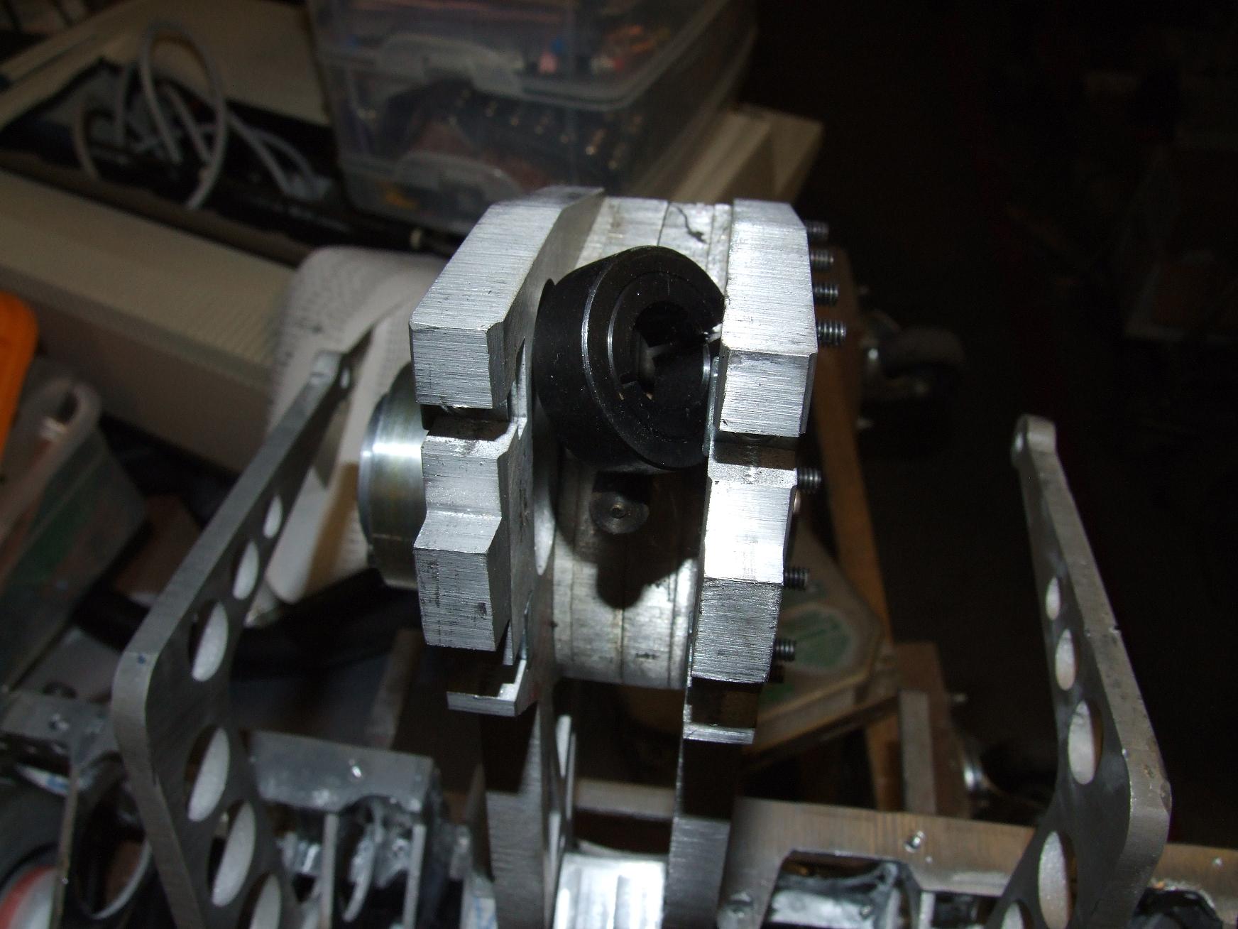
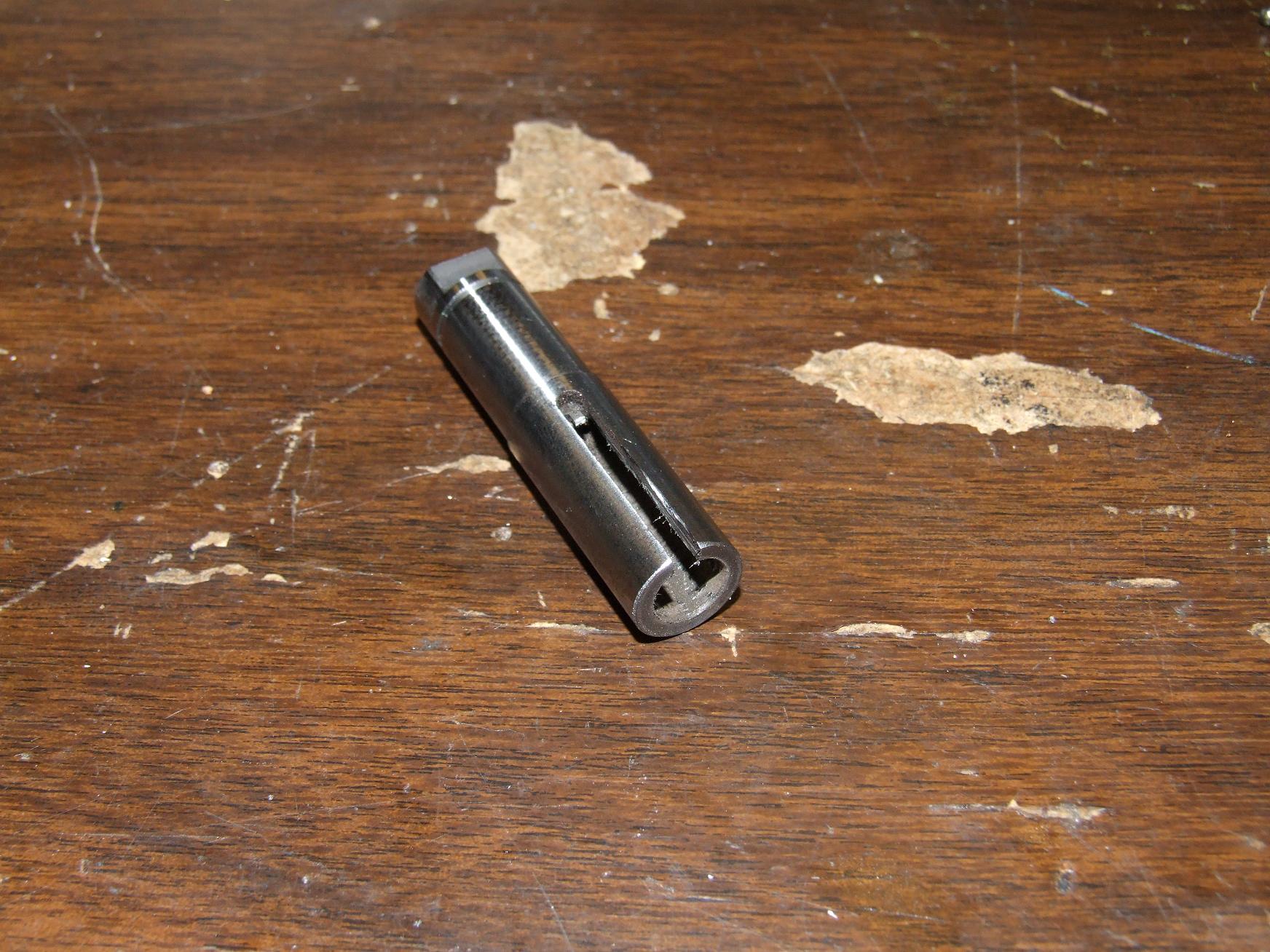
Everything would have gone smoothly if I had remembered that there was actually no way of inserting the shaft collar into the assembly unless it was a two-piece split one. I didn’t, so I bought a bunch of normal 1/2″ collars.
Sadly enough, a 1.125″ diameter collar will not fit down a 7/8″ wide gap.
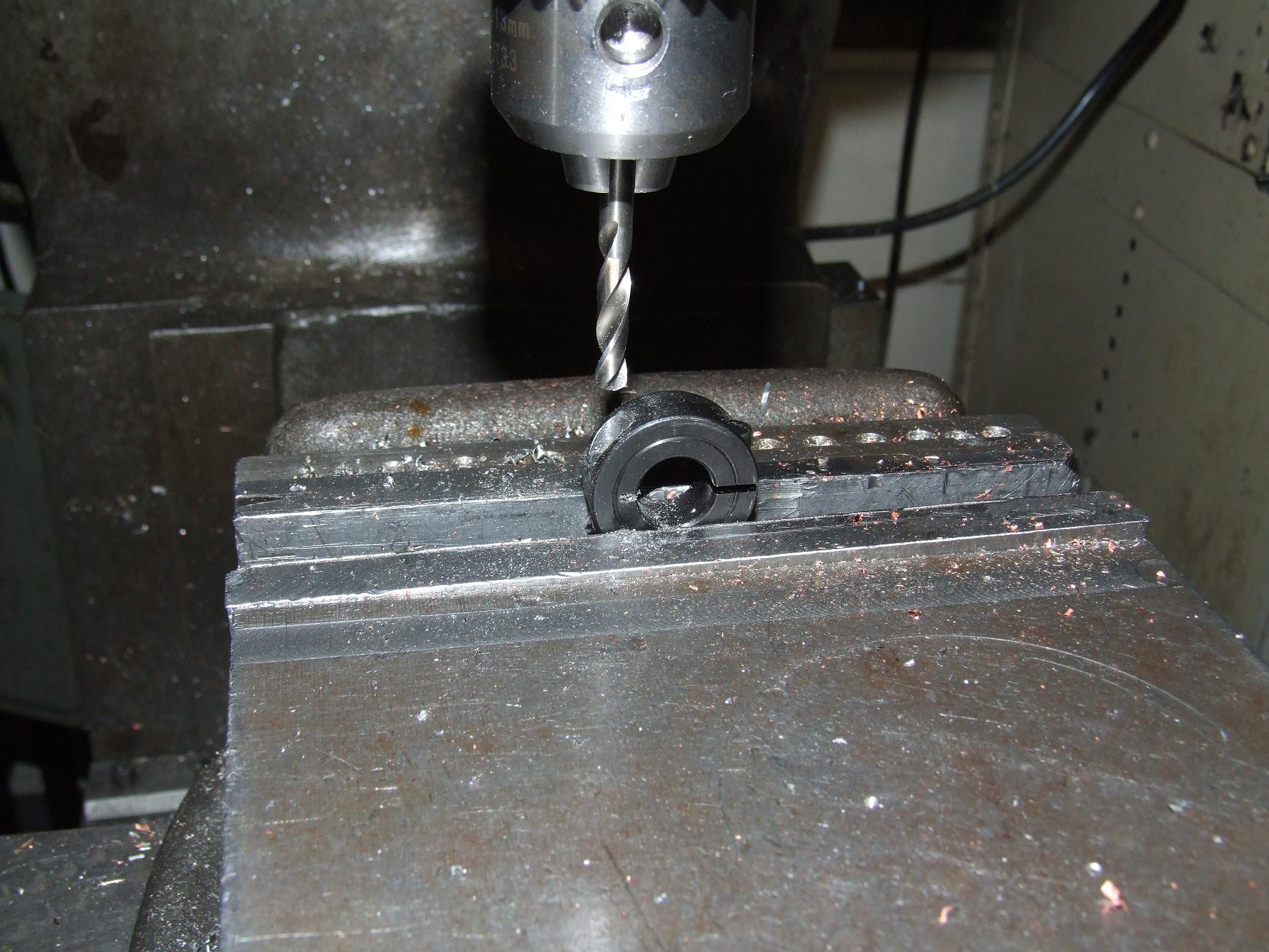
Solution: Just turn the thing into your own 2 piece collar. Step one is to mill a counterbore for the screw on the non-split side. Then drill a tap hole, tap the threads, and drill a clearance hole a little bit past halfway down.
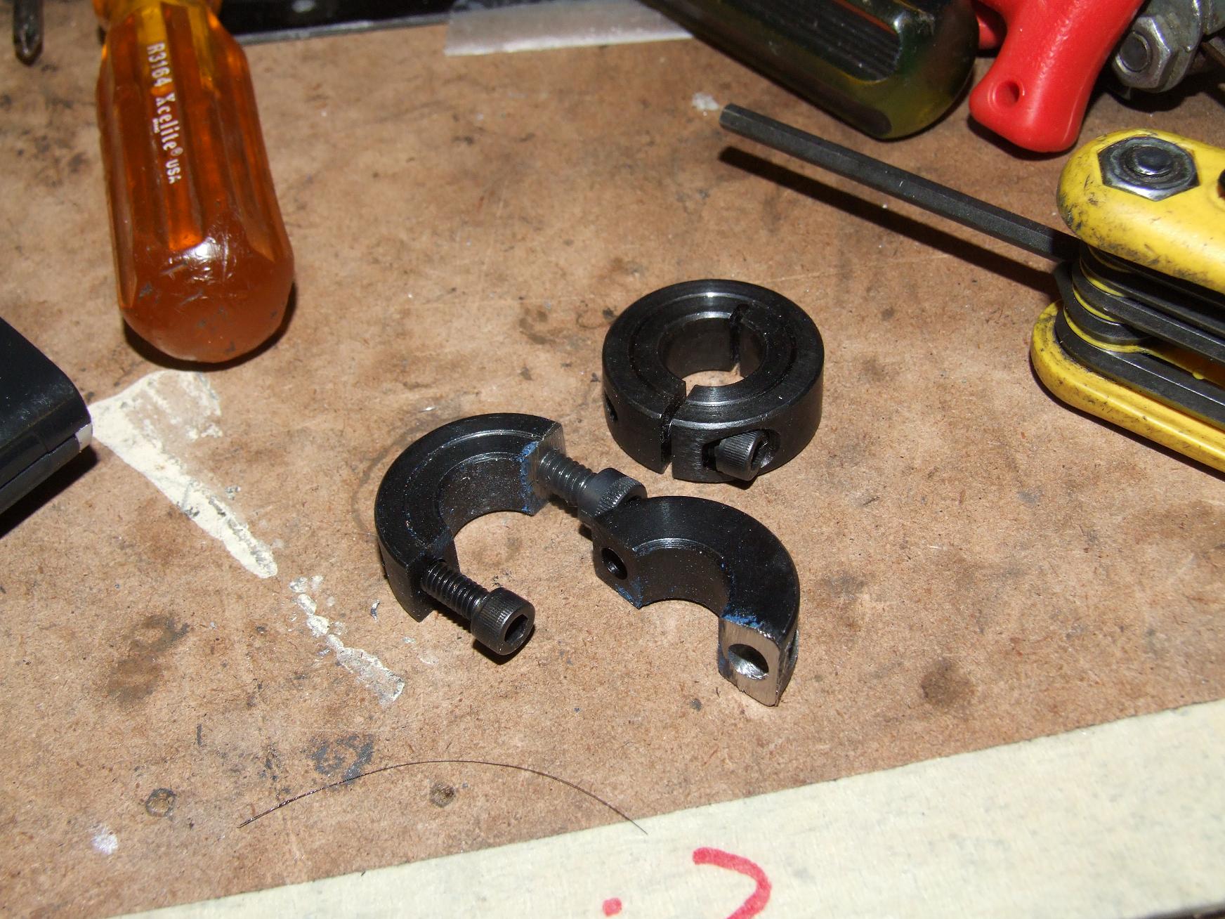
Then viciously hacksaw the thing in half. Clean up the carcass on the grinder, and mezzopiano, a two piece shaft collar.
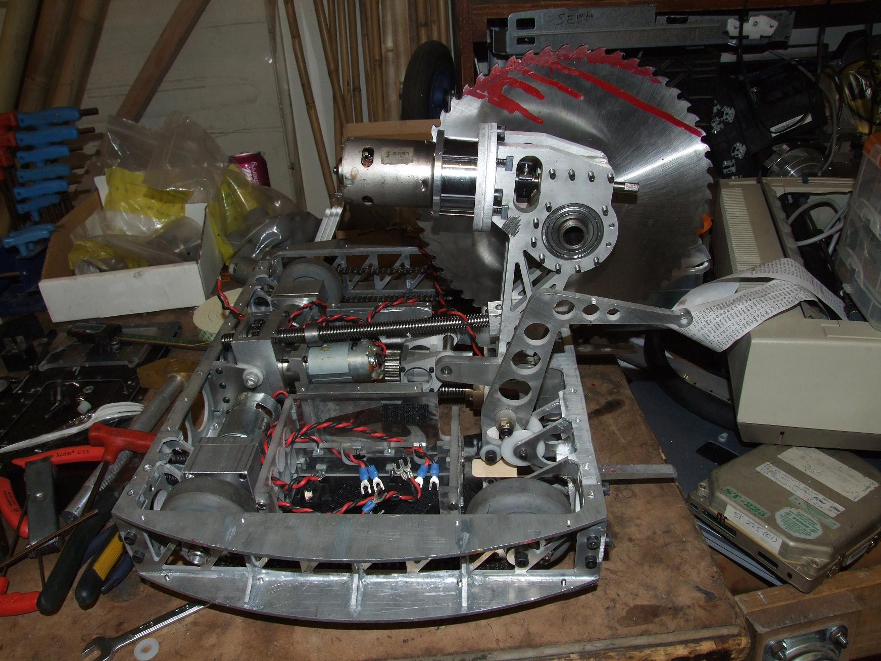
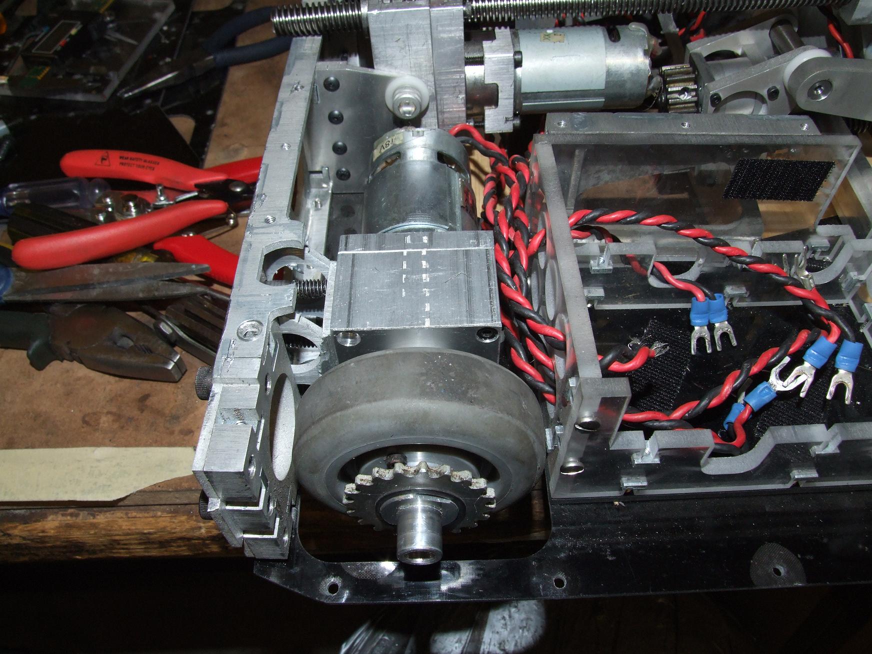
Perfection. Here’s a little bit of saw flexing – overall, the travel is the same as before the actuator mods.
That’s it. The bot is mechanically complete. All the actuated systems move to my satisfaction, and the drive motors both work.
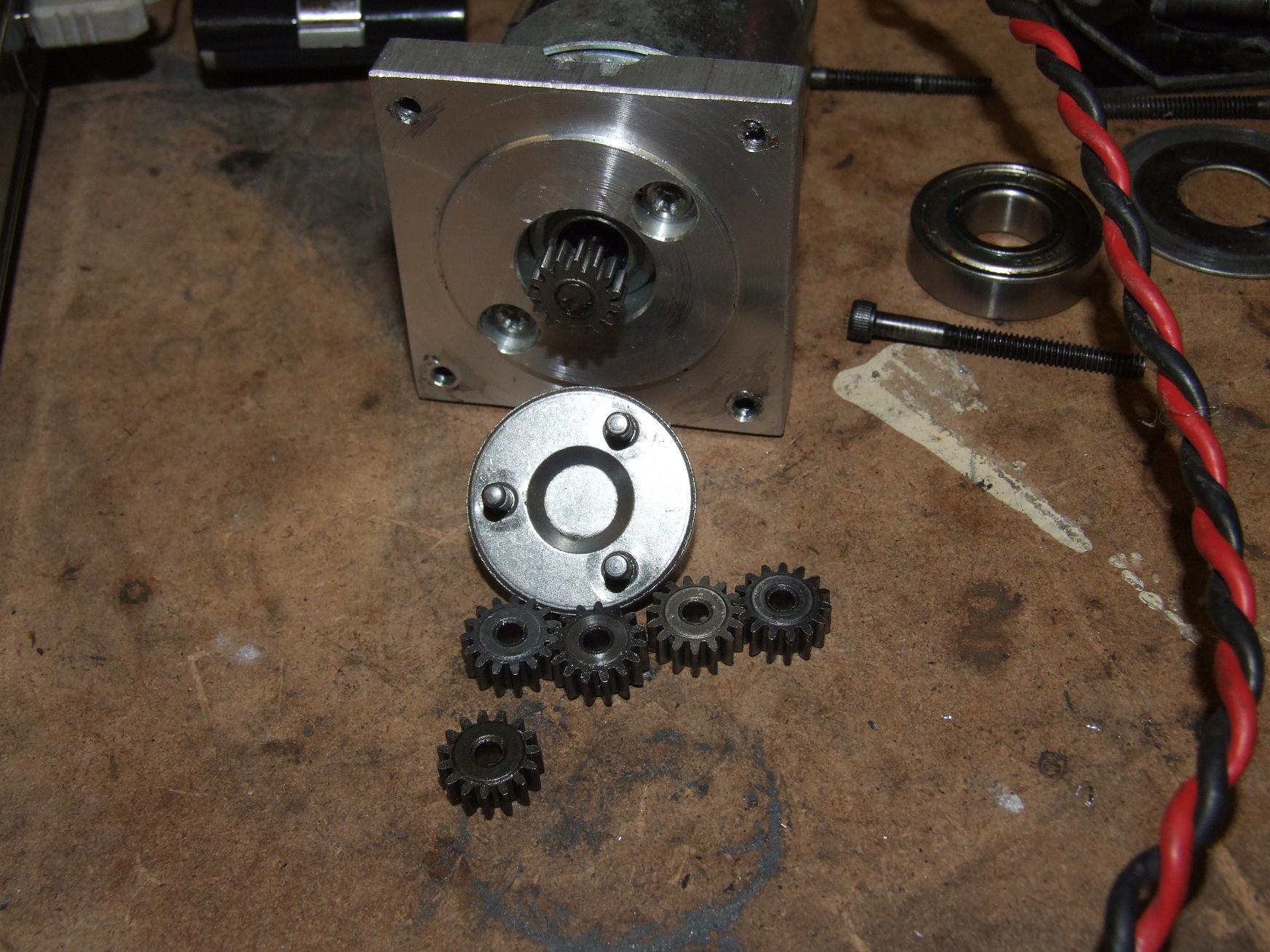
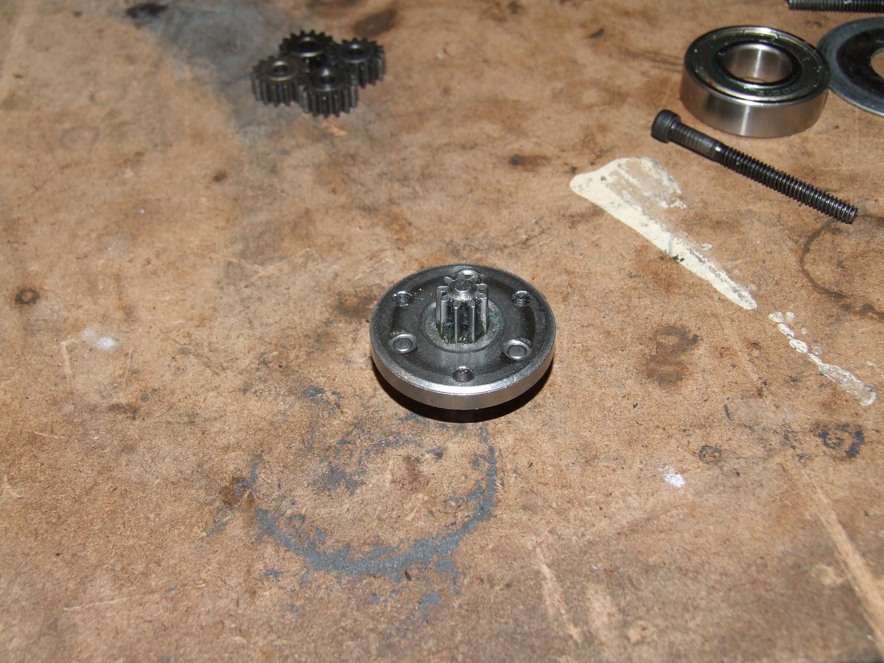
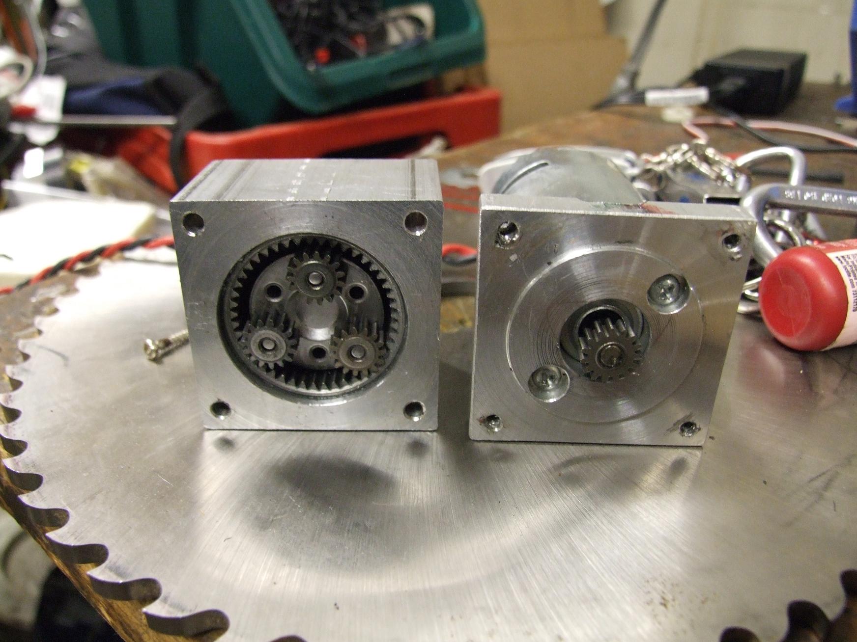
I discovered that the saw drew an absurd 33 amps just cruising, no load, at the full 24 volts. The cause for this was traced to the worm gearbox input shaft bushings. When the Preduction was added to the system, its ball bearing output and the two shaft bushings formed an undesirable overconstrained shaft. Essentially, the shaft has to bend at the first input bushing because the major end constraints are the very frontmost bushing and the Preduction ball bearing.
This might have been tolerable (and therefore a hidden problem) if the worm box came with ball bearings too, but with bushings, this causes massive friction. Just removing that bushing dropped the no-load amps to 17. Still high, but the MEV-alike draws 7 amps no-load already, and the rest I can realistically say is disappearing somewhere in the geartrain.
electriclulz
It’s time for that part of a project where everything usually goes horribly wrong.
The first thing to go wrong is my discovery that the fully loaded bot weighed only 27 pounds. With the greatly increased current demands of the saw motor, I elected to balance the weight by putting in a larger battery pack.
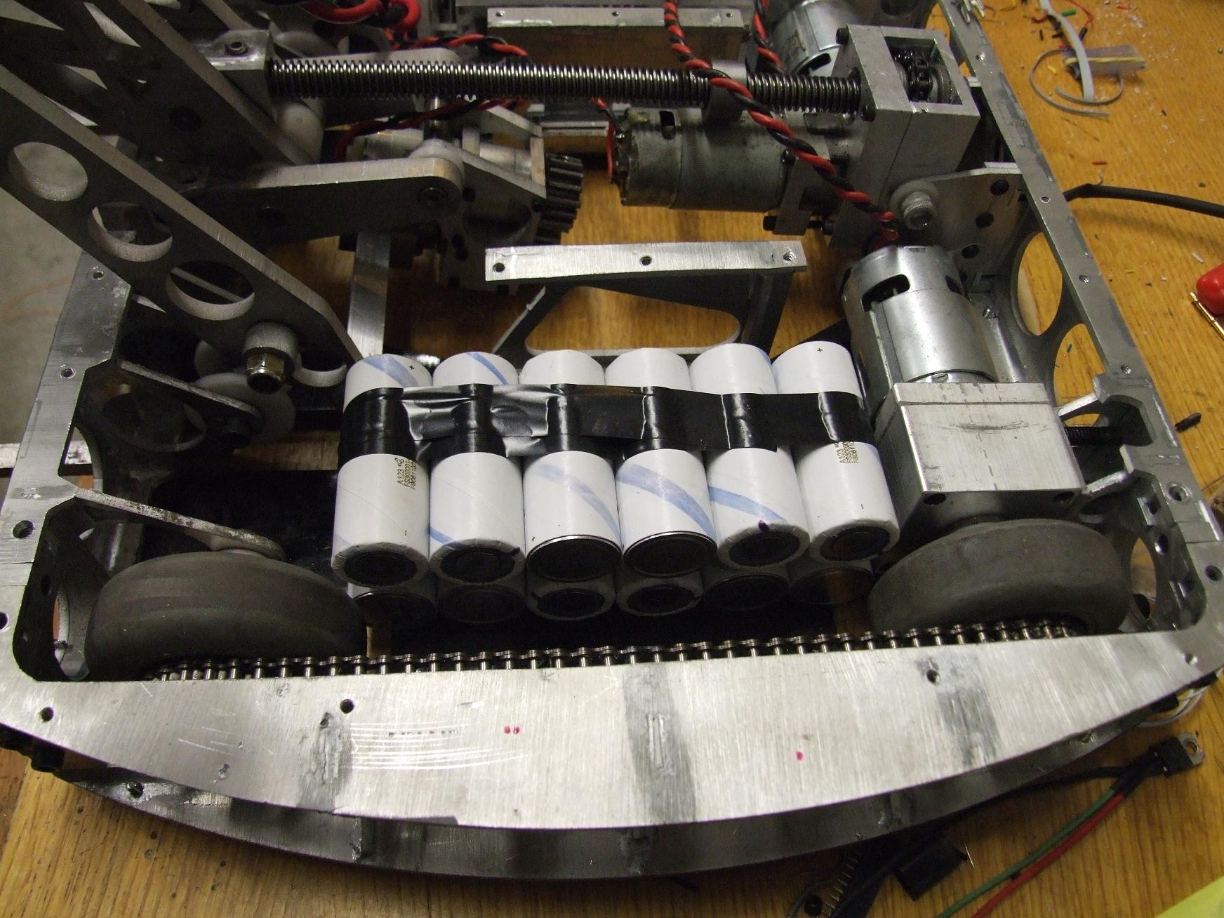
Above is the planned 6S2P arrangement of 26650 cells. The whole thing just barely fits between the drive wheels, the motor, and the front claws.
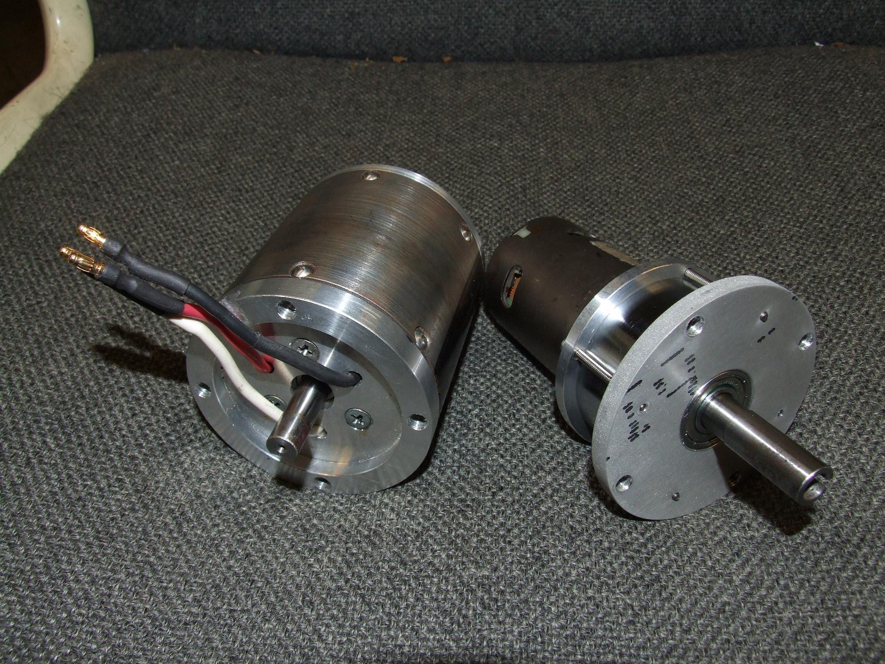
Going down to 6S relieves the motors of alot of strain. The 700 size drive motors already get pretty toasty, and the MEV-alike is a 12 volt motor. Things were really unhappy on 24v, and the single-parallel pack was being drawn down pretty quickly at Moto. Therefore, I’m also using 2 cells in parallel, each group forming a single metacell like on the METALPAXXX.
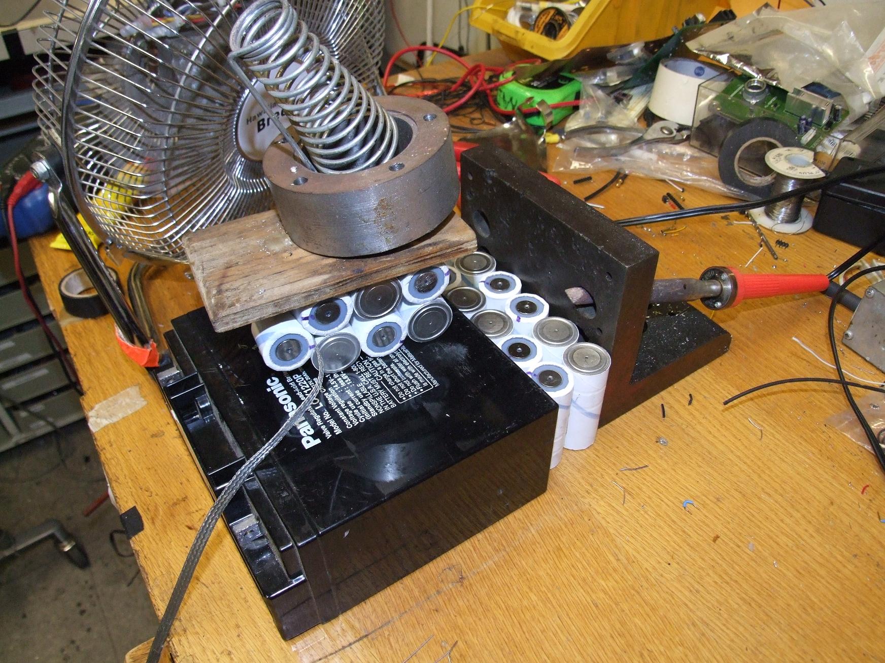
First thing to do is to put the cells together in bricks. I went my usual route of using Automotive Goop adhesive between the cells, then binding them with electrical tape and leaving the adhesive to set. Also pictured is a spare 7S1P pack for Clocker.

The 200th Cold Arbor build pic is of the infant Arborpack. I performed my usual grounding braid assembly method here – nothing particularly special

And here is the complete pack, with balance leads and after being double bottleshrunk.
Because the new battery arrangement precludes the use of the existing 1/8″ polycarbonate armored battery box, I elected to give these cells an extra layer of protection… or two, rather. I bought (and subsequently emptied to the detriment of my health) more cheap 3-liter sodas and cut up the bottles. With some quality heat gun time, the bottles shrink around the battery pack and then harden into a thick plastic shell.
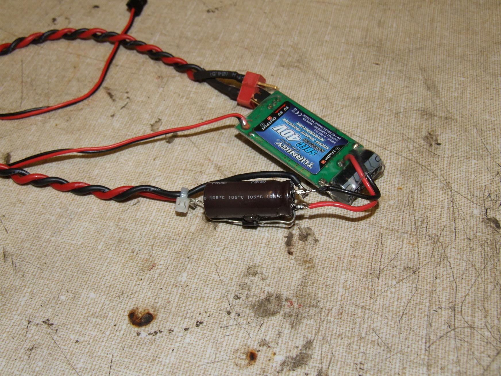
Once again, in anticipation of the potential for high pulsed current demands from the saw motor, I threw a diode-capacitor buffer in line with the receiver’s power source, a cheap Hobbyking BEC. The diode sits between the main battery and the BEC input and essentially makes sure a sudden voltage dip in the rest of the system cannot upset the BEC. The large buffer cap should carry the BEC demand through transients.
I built the “check valve” system because I was planning on using a giant relay and a receiver-controlled switch to turn on the DC motor.
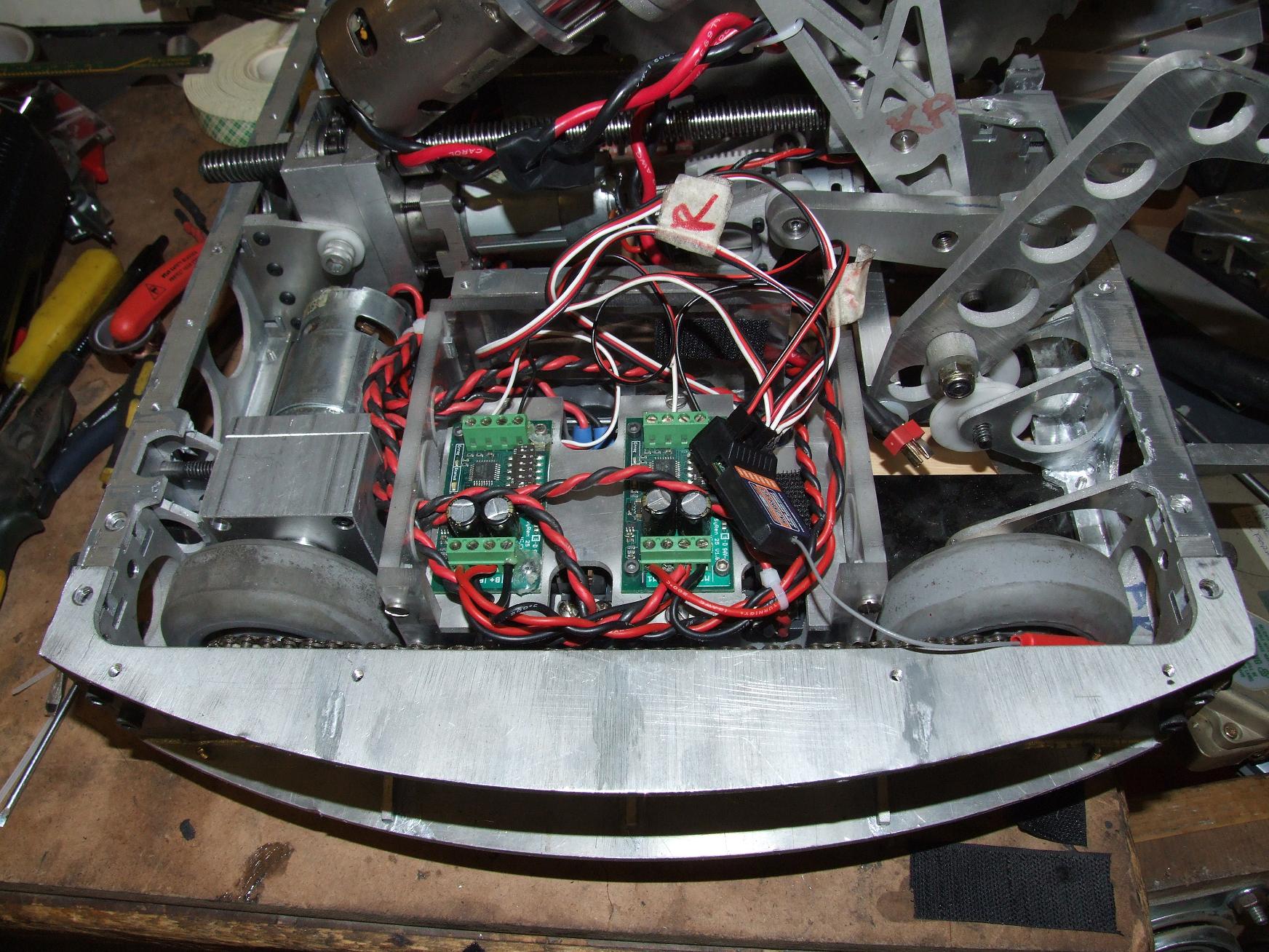
Loading the electronics back into the bot!
Rewiring Arbor was simple because the controllers were not stripped of their wiring, and the motors all had pigtail leads. So this process in total took maybe two hours, with plenty of wanking time allotted.

And a quick finishing shot from the front. By this time, I had already taken the bot on a (sawless) test drive or two. The McMasterbots wheels wear pretty quickly – I’m going to have to order spares. Not for D*C, but later on. As of the picture time, the RCS order had not yet arrived, so the saw wasn’t up and running.
ninjabridge
A relay-controlled weapon motor. Really? A relay? Really now, I think I can do better than that. If I couldn’t buy a forward-only, 24 volt compatible, variable speed DC motor controller, can’t I just build one?
These thoughts were cycling through my head as I was assembling the most impulsive electronics project ever – Ninjabridge.

Ninjabridge is composed of a Pro Mini Arduino, an IR(S?!)21844 synchronous half-bridge gate driver hidden under the Arduino, and four IRFB3006 FETs. It is (will be, after I add wires and software) a foward-and-brake controller with inherent synchronous rectification. With two 3006s per leg, I should get at least 40 or 50 amps continuous out of this thing with no additional heat sinking. Modern silicon is niiiice.
I’ve actually been in the design stages of a full robot controller – 4 channels of H-bridge DC motor drive and one single direction half bridge for weapon work, up to 36 volt operation at 40-50 amps continuous, all featuring implicit synchrec. I originally wanted to get the boards made and the whole thing ready for Dragon Con for use in this very robot, but decided against risking everything when I had otherwise functional controllers.
But there exists a “controller gap” in the medium power (12-36v, 30 to 60 amps) range as of right now. Above this range, you have the venerable IFI Victors, and below this are the popular small robot controllers like Scorpion XLs, and the Dimension controllers that Arbor uses on its actuators. I’m not intending on striking out in the market with anything, but I want to see what’s possible with modern semiconductor and IC technology. And to this end, I think the above features are fully reasonable to pack into a space the size of at most two Victors (which are pretty large controllers).
I’ll track down more 12 gauge noodle wire for Ninjabridge and then spend a few weeks…err… hours coding up a basic single channel R/C compatible controller. Then maybe Arbor can actually damage something.