It’s serious Clocker time!
I’ve spent some time practicing my TIG wielding ability on small steel objects as well as reading back up on ways to make steel less temperamental (or perhaps more tempered). The results have not been scientifically verified nor even experimentally confirmed legitimate, but at least it looks kind of cool.
Last time, my TIG welding adventure left off with my little pins breaking off one by one because of my muscle-memory water quenching. I wrote those off to practicing the technique itself. Doing these pins was relatively easy, I think, because it didn’t actually involve trying to hover the tungsten over a path – just kind of wiggling it in place. Some kind TIG advice from friends also helped. After I went through 2 more scrappy shafts, I decided to do the real things:

Oh man, those just about don’t even need any machining to flatten the upper face. I had to cut short my desire to TIG WELD THE EVERYTHING such that I stand a chance of finishing the bot on time. These shafts were both preheated to the “nice golden brown” stage (260C or thereabouts), welded on 80 amps, then quenched in cold water. I then tossed them in the convenient MITERS tiny heat treating oven (interior dimensions of a 4″ cube) set to about 300C, for a nice blue finish, wherein they baked for about 2 hours before being quenched once more.
Now, it’s important to point out that there is absolutely no scientific basis behind the choice of temperatures. I don’t even know what steel these things are made off, past a crude scratch test with some known 1018 steel plate. The shaft itself is definitely a really really mild steel, and I’m hard pressed to believe the pins are that much higher carbon. Remembering some rumors and gossip on the CheifDelphi forums from my 2007 FIRST Robotics season when the Banebots P80s (back when they were just called “56mm” gearboxes) had carrier plates made of what was found to be essentially 1006-1008 (very low carbon) steel, I think I’m not far off base.
I based the preheat on the assumption that they at least resemble a medium carbon (.40% to .60%) steel in some industrial applications, as well as the tempering temperature, figuring that the mildest of mild steel shaft body wouldn’t do anything noticeable.
I really, really should take these things to the materials lab and do a real hardness test if they ever break. Even I’m a little curious now.

The next stage after my brownies baked to perfection was to machine the taper. Luckily, the taper turning attachment for the trusty Old Mercedes (the MITERS 1953 model South Bend 10L) has not disappeared since I made these shafts the first time 3 years ago. There’s not much I can say to explain the taper turning doohickey besides pointing to this video which shows a very similar conceptually (but different in layout) device.
I discovered after finishing these pieces that my previous tapers were not only not the size the drawing said they were, but were actually 2 different sizes. The gears apparently had different bores. Fortunately the bores were smaller than indicated, so I had to just keep making small passes while trying the gears on every once in a while.
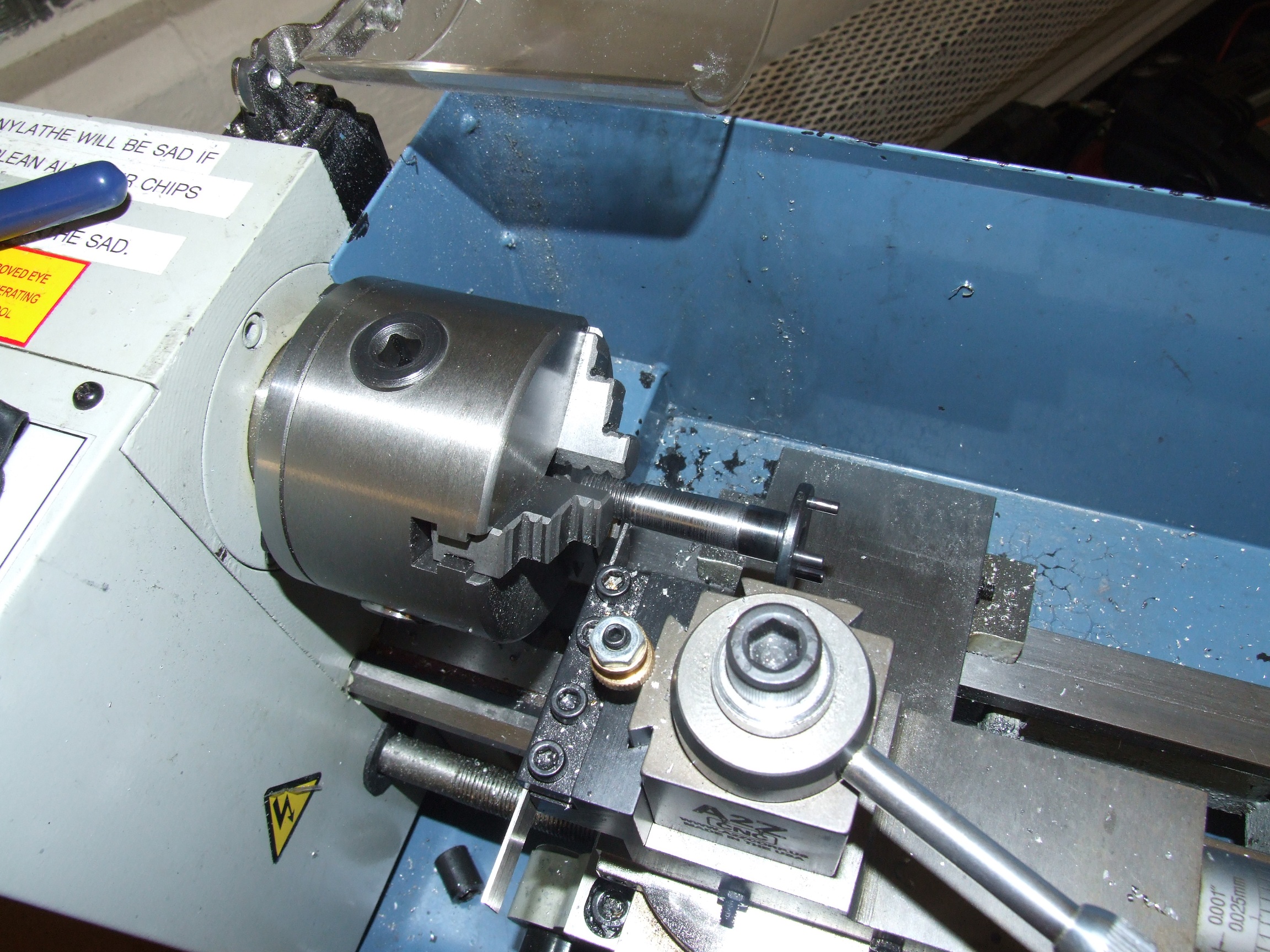
Different setup, different machine, once again.
Tinylathe was used to make the retaining ring groove on the nontapered shoulder because its tiny adorable .040″ parting tool is precisely the width of one of the snap rings I’m using. The only parting tool available for the bigger machine was .125″ wide, which I really do not like – it’s really too wide for the machine’s age-induced lack of alignment and the tool holder’s non-stiffness. I regularly machine on the big 10L and then part off on Tinylathe now.
Luckily, the “3 degrees” I eyeballed this time is the same “3 degrees” I eyeballed in 2009. I did quite a few verification fits to make sure the distance between the gear and housing was close to 1/16″. A little sandpaper-polishing was involved to very finely bring the diameter of the tapers down at the end.
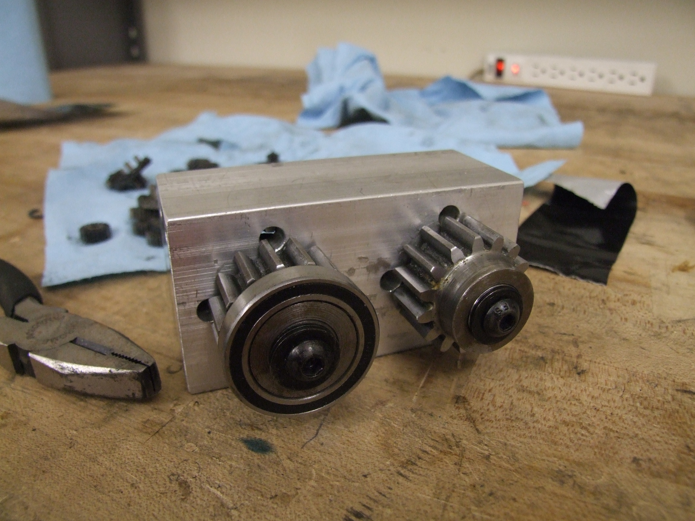
Fully assembled and packed with not only grease but fresh gears!
I think this is the first time in 2.5 years that this gearbox has not made terrible grinding sounds when the lifter was being run.
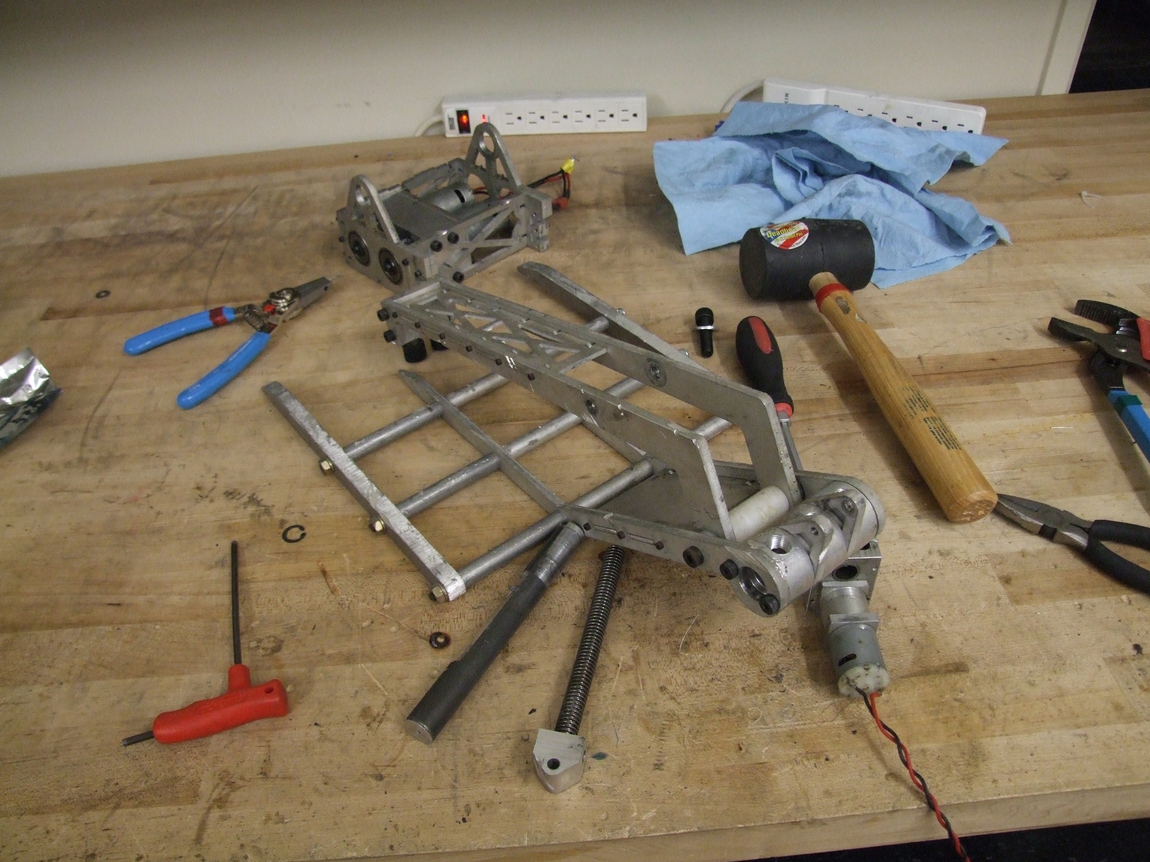
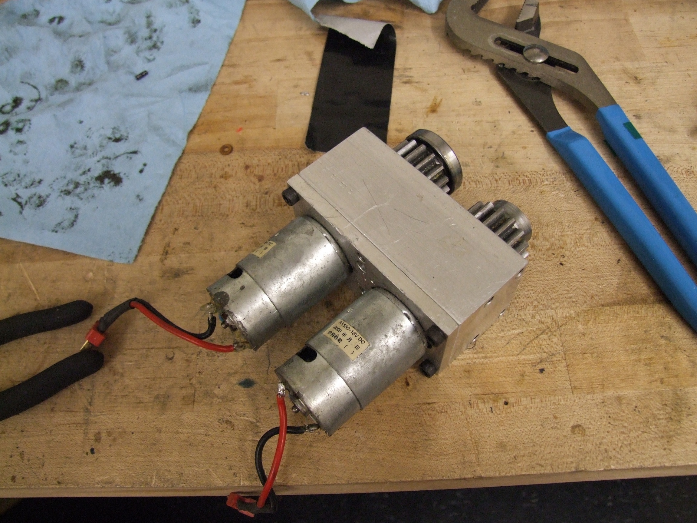
Unfortunately, Clocker will only get more taken apart before it gets put back together at this point.
the upgrades
Several major changes will be happening to Clocker this time around, things which I should have done immediately after discovering it wasn’t doing the robot thing properly, but were neglected due to lack of roboner.
The first, and most simple change which could make it far more effective, is moving to 3 inch wheels:

Clocker was originally designed with 2.5″ wheels because I was still totally into flat robots then, and the ground clearance afforded by 2.5″ wheels, half an inch, was enough for the Robot Battle stage at the time. Unfortunately, wheels get smaller over time, and stages also get torn up (on purpose) – last year, it got to the point where Clocker had too little ground clearance margin to even move around reliably. In a game where there are no arena walls, moving around reliably is like 90% of the match.
Going to 3″ “McMasterBots” 40A wheels will up the native ground clearance to 3/4 inch. While having your bot higher off the ground may make it more prone to getting wedged, it’s also easier to get away, and there will likely be very few wedges where I’m going anyway (cept mine of course)
I’ve designed a new hub which is made of a convenient stack of plates with a Delrin bushing in the center. This time, everything just bolt through the whole wheel instead of transmiting through the aluminum hub body and into a press fit as the current hubs are set up.

Going up in wheel size is going to require me to make some changes to the robot’s frame, as several elements were designed only with 2.5″ wheels in mind. The front ‘shocks’, for instance, have to be moved inboard more and the shoulder screw head can’t stick out any more. This is fairly simple – I’m just going to mill down that portion of the rod end. The ‘plate’ at the left which bridges the two front leg halves will also have a little chunk milled out of it.
The rear ‘corner block’ in the frame will also need to have its thickness reduced, since a 3″ wheel will be exactly rubbing on it.
These were the simple changes.
I’ve been dissatisfied with Clocker’s upper clamp arm since I built the thing. Two major reasons: First, the actuator I used on it is just a little 400-class motor feeding into a 20:1 Banebots 28mm gearbox (of which production has been stopped for several years, leaving me with no practical spares), driving a leadscrew. It has no real clamping force whatsoever, nor can it help the robot recover if it flips over while body-slamming an opponent (this has happened a few times).
Last, and worst of all, the motor is the hard stop for its own range of travel! The separation distance between the motor axis and the leadscrew axis, for some reason, was made as small as possible ,meaning the motor is the first thing to run into the leadscrew anchor by the main fork. This has happened once, and I literally bent my motor. This actuator was one of those things that I look at later on and can only go “…” at.
So why not just flip the motor around so it sticks out foward? Then it would have stuck straight up in the air above the clamping fork (and been the first thing to hit the ground when the robot gets flipped), or it would have stuck really far into the ‘clamping volume’ and been the first thing to land on the opponent when the fork came down.
Stuck between a rock, hard place, and its own leadscrew anchor.
All of this lead to a night or two of thinking of, sketching out, and just manipulating solid part models around a new upper fork and motor layout.

Here’s what’s going on. This is arrangement candidate number 1, top actuator with motor facing away from main pivot point.
Notice that the motor is actually Cold Arbor’s saw actuator? I decided this early on that I wasn’t going to make yet another new custom linear actuator when I had a perfectly workable one already kicking around. The 550 will add alot more force to the grip, and I’m going to use it as a chance to test out asymmetric current limiting on the Ragebridges – stronger release/lift current than grab/lower.
This arrangement was created purely as an iterative design step. It’s really quite terrible. First, the motor’s really exposed and if I grab an opponent, an edge of it might just punch my motor from below. Second, the center of mass of the very heavy actuator is quite far out from the fork’s main pivot. I’d want it as close as possible in the best case.
Finally, notice the much deeper fork. Clocker was designed pretty much to grab only flat, boxy pushybots, so it really could not grab anything over 4 or 5 inches. Well, there’s lots of bots that are 6″ and taller, so the deeper fork is designed to accommodate them now too. This, too, was on its first iteration and the following screenshots will show little geometric changes.

Part of the reason Clocker couldn’t grab taller bots was because the clamp could only open so far before, again, the actuator ran itself into the leadscrew mount balls first. I aimed to resolve that problem in the new geometry – here’s a shot of the new top clamp beign able to reach about 55 degrees of swing. This is actually physically impossible because the clamp arm would run into the main fork axle parts – but it can reach 45 degrees with no problem. Previously, the maximum angle attainable was only about 35 degrees…

Here’s arrangement candidate #3 (Number 2 was just a variant of #1 with the motor turned around). Now we’re getting somewhere.
The motor is mounted very low and aft, meaning my C.G. remains where it should be. The motor no longer travels a significant amount linearly when raising or lowering the clamp arm, since it is mounted to the fork instead. The leadscrew anchor, formerly at the end of the egg-cam looking thing on the right (in the profile of the main lifter gear), is now directly installed on the clamping arm.

And here’s how far back the arrangement can push the clamp arm. I briefly considered adding an ‘indent’ to the clamp arm so it can partially overlap the pivot hubs, and this may creep back into the design later on.
The motor, while it does intrude a little on ‘clamp space’, can be better shielded from things landing on it in this configuration. I like it alot.

A better shot of how the clamp motor will be mounted. Notice it now has its own little roo-bar structure in front of it – this will be a ‘hard stop’ for incoming robots. It won’t protect too well against other robots’ pokey things, so I may turn it into a plate (or have it swappable with a plate) for very pokey robots.
The summary of these changes is:

Here’s what else has changed.
- The outer set of forks has been made thinner to compensate for some of the weight of the heavier actuator. The outer forks on Clocker are currently 1/2″ aluminum and have seen pretty much zero damage.
- The clamp arm itself has been lightened by several ounces, again to account for the weight of the actuator. It should be just as stiff as the current one due to more vertical thickness (where it counts). I put a huge radius on the corner where the actuator is pulling on it so it doesn’t embarassingly break off.
- The two little grabby-toes on the end of the clamp arm have been replaced with one.
Why? I bought replacements for them yesterday and I hit the wrong part number on McMaster. The ones I ordered are 1.25″ diameter with a huge 3/8″ threaded stud. I’m definitely not using 2 of those, because while the thought of force-teabagging your opponent with double huge rubber knobs is hilarious, it would be impractically wide. Also, using 1 is lighter and allows me to save some weight from the most important location – the very end of the long arm.
timeline
NOW.
NOW.
NOWNOWNOWNOWNOWNOW.
I’ve already done most of the preparation machining such as preparing the frame for new motors and modifying the Cold Arbor saw actuator for its new home. Clocker’s pretty much been broken down into component molecules, and I just need to cut out the new arm and drive pieces. It needs to come back together by Monday night.


