Snuffles Reloaded: Update x[n]+2x[n-1]-x[n-2]

It’s getting closer.

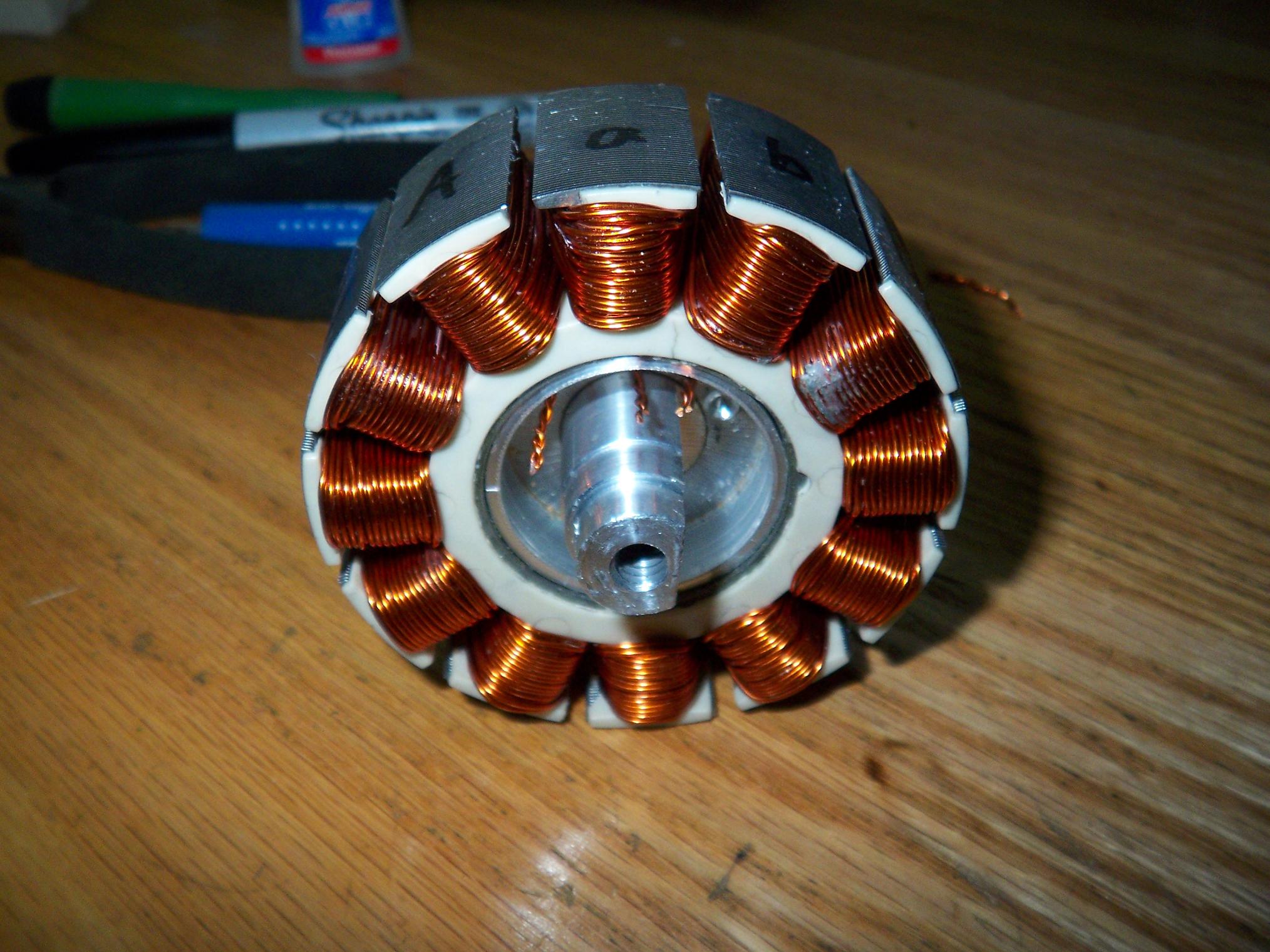
In the last episode, the can was filled with magnets and the stator was test wound. I settled on 25 turns per tooth, distributed LRK style, as a starting point, and proceeded to wind the whole thing.

And here it is. This took quite a bit of time, as I had to make about 300 little wire loops in total and make sure they’re all aligned and not overlapping as to have the maximum space efficiency.

I initially bolted the stator to the end of a metal flat clamped to a table so I could tug a bit harder. After it took an hour to do half of one phase and after I discovered I could go much faster and pack as well by hand, I ditched it.

One quirk about the LRK scheme is that one phase is wound from the opposite side of the stator from the other two. I neglected that fact, and while it doesn’t impact the performance of the motor in any way, makes my termination slightly inconsistent, resulting in the need to fudge a bit to link the common ends of the windings. So… yeah, start the bB phase from the other side.

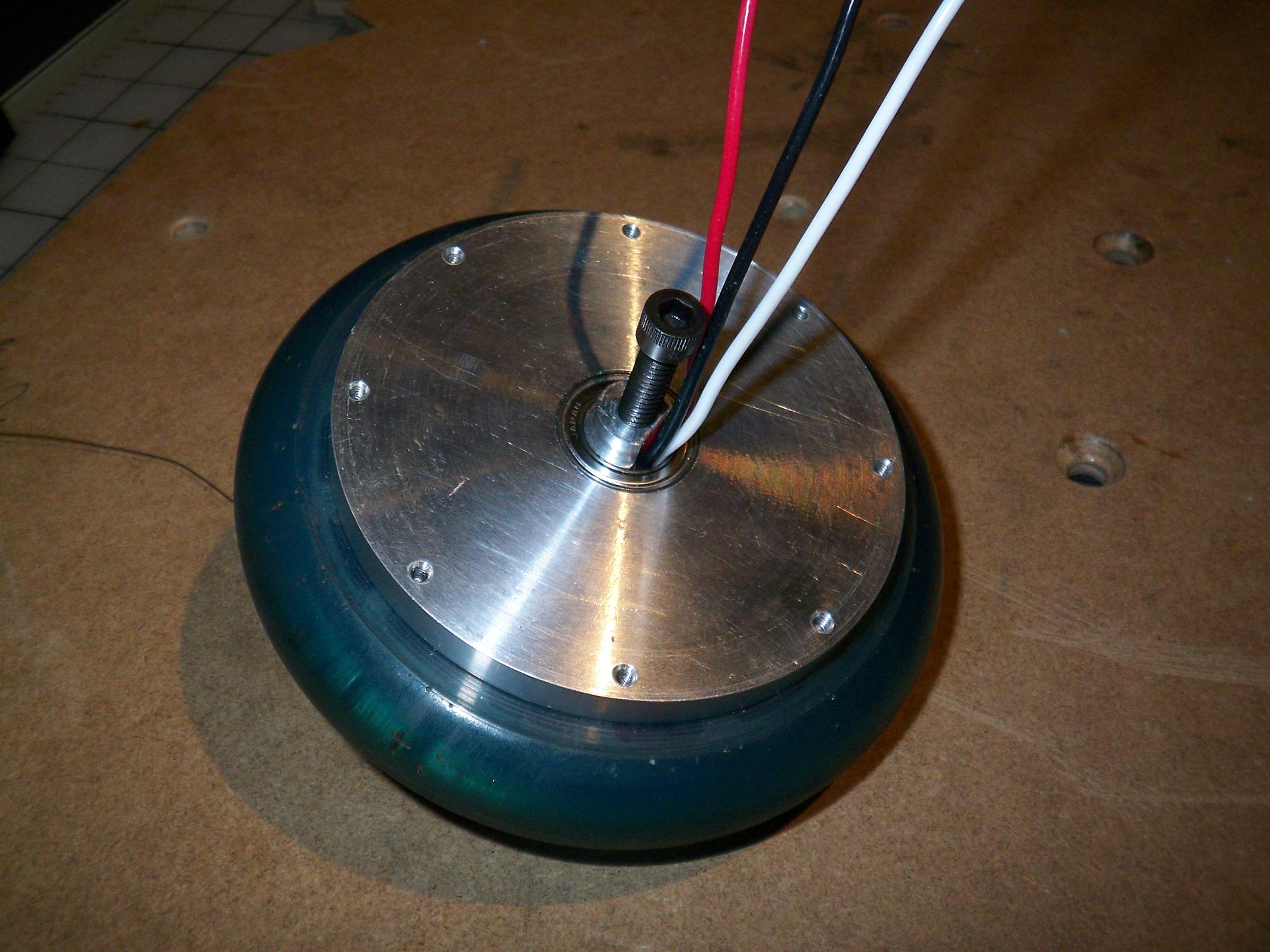
From the other side. The terminations exit from 3 holes drilled in the core mount thing, and then through the space between the motor bearing and the shaft flat. I found that this was a better way to do it than running everything through the center of the shaft.

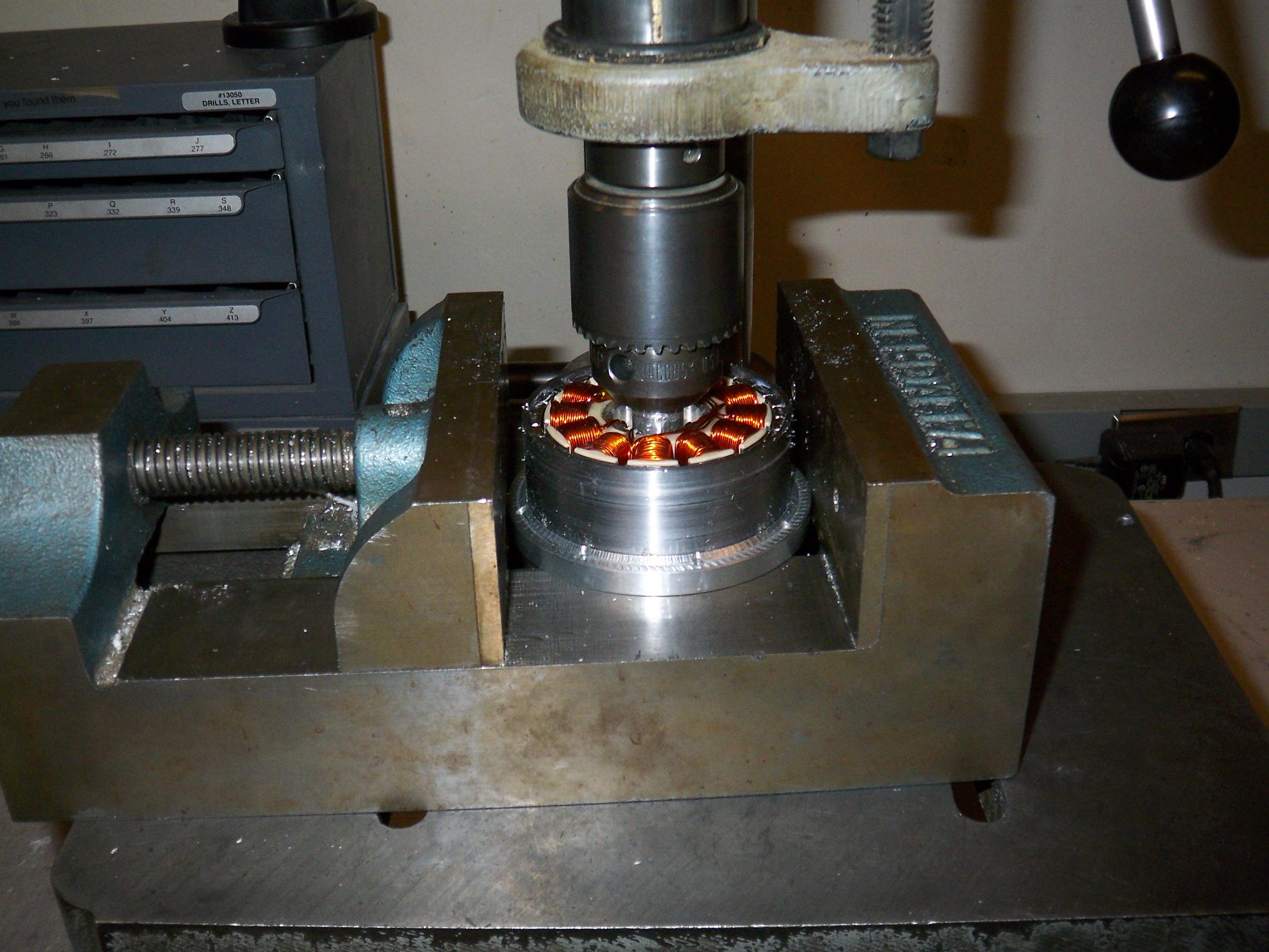
So after the pigtails were soldered on and everything secured by a good helping of epoxy, it was time to drop the stator in. This was not trivial, because I could not hold onto the thing while they were being brought together since the magnetic pull was so strong.

In the end, a giant vise and the quill of a drill press came to the rescue. It may pull hard, but not hard enough to overcome a 50 pound vise.

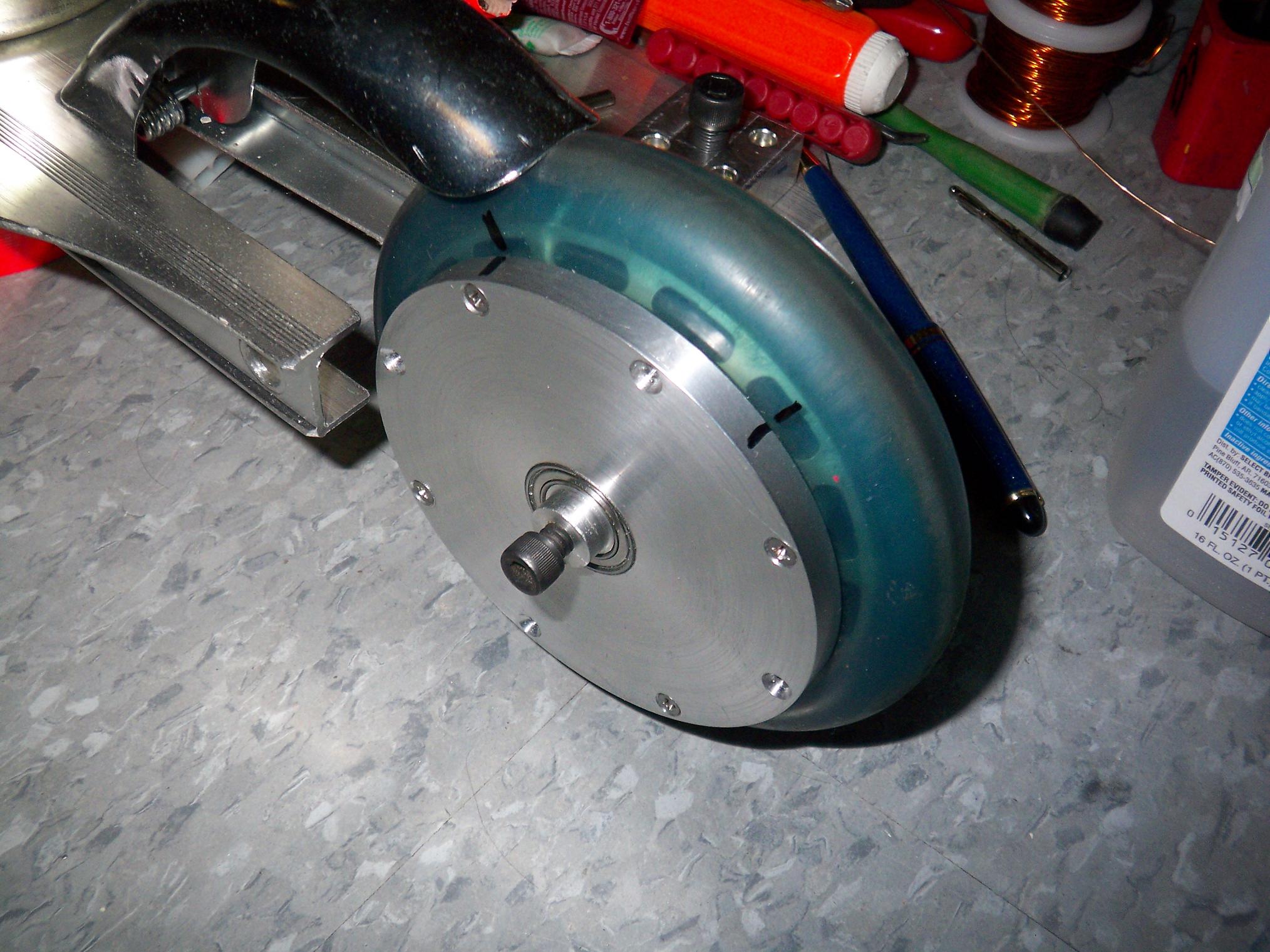
Completed motor, side one…

Completed motor, side 2.

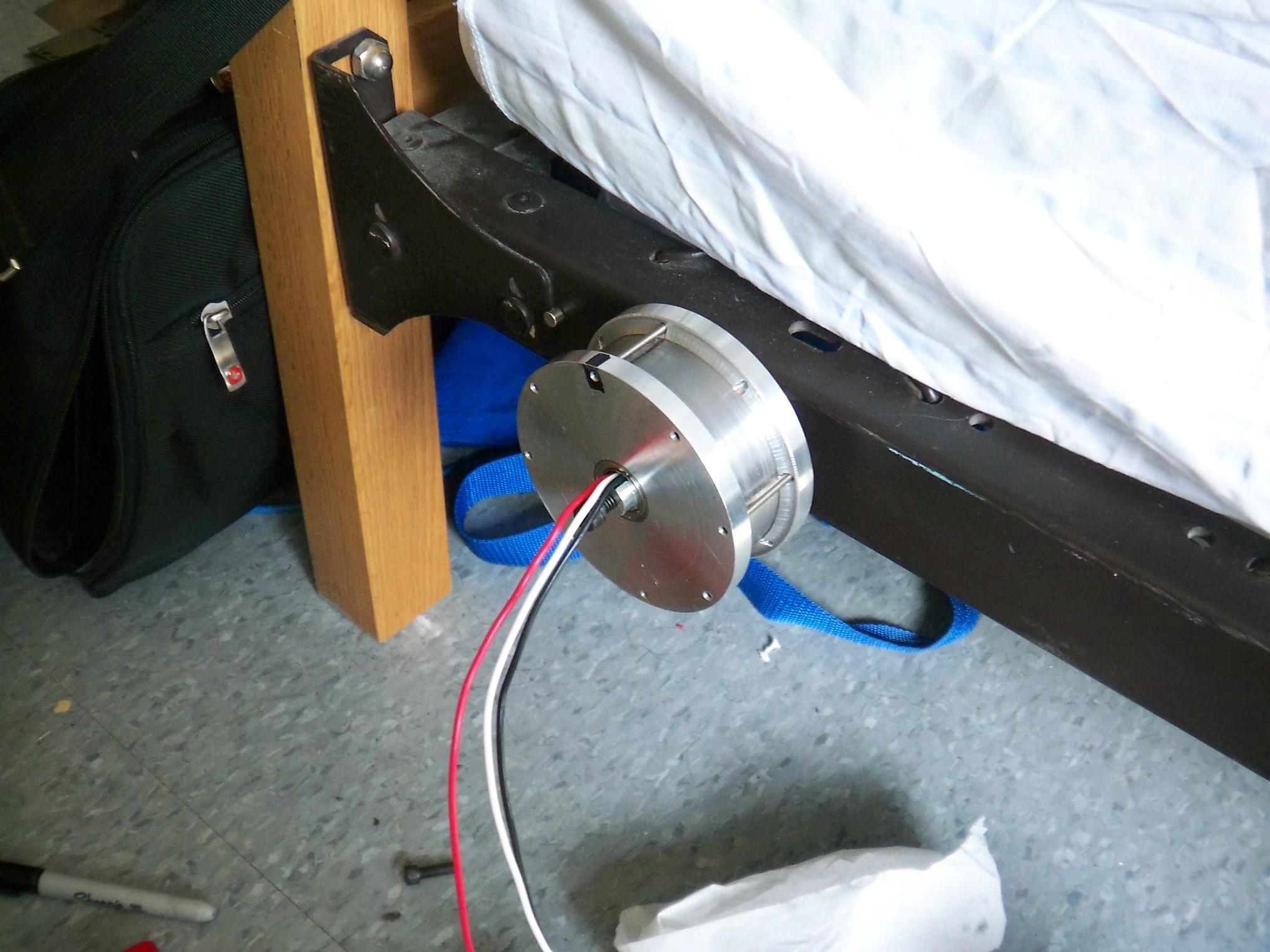
So now that it was put together, it was time for a test run. Of course, I neglected to bring my stator mounting pole back with me from MITERS, so I bolted it to the nearest object that had a 1/4″ hole in it.

Conveniently, it was my Institvte-provided bedframe. This brings up great visions of motorized furniture, but that’s another project for another day.

Here’s a video of the first firing of the motor. It’s a bit choppy – One of the side plates is not a good press fit, which, along with the poor molding tolerances of the wheel, caused the side place to mount a bit off-axis.

Using a drill motor with a wheel, I was able to calculate how fast the wheelmotor was rotating at a given drill motor voltage, and correlate it with the AC voltage it was producing at the leads. This gave me a working value for the voltage vonstant Kv, which tells how fast the motor turns given a certain voltage and an unlimited power source.

I worked out the number to be around 65, since it should have been rotating about 306 RPM given my 900RPM drill motor. It was producing 4.7 AC volts at that speed. An actual tachometer will give a more precise reading (and can do one better by factoring in system losses since it’s measuring the motor RPM while driven). Most likely, it’s higher than this, but not by much.

Anyone have a tach I can borrow?

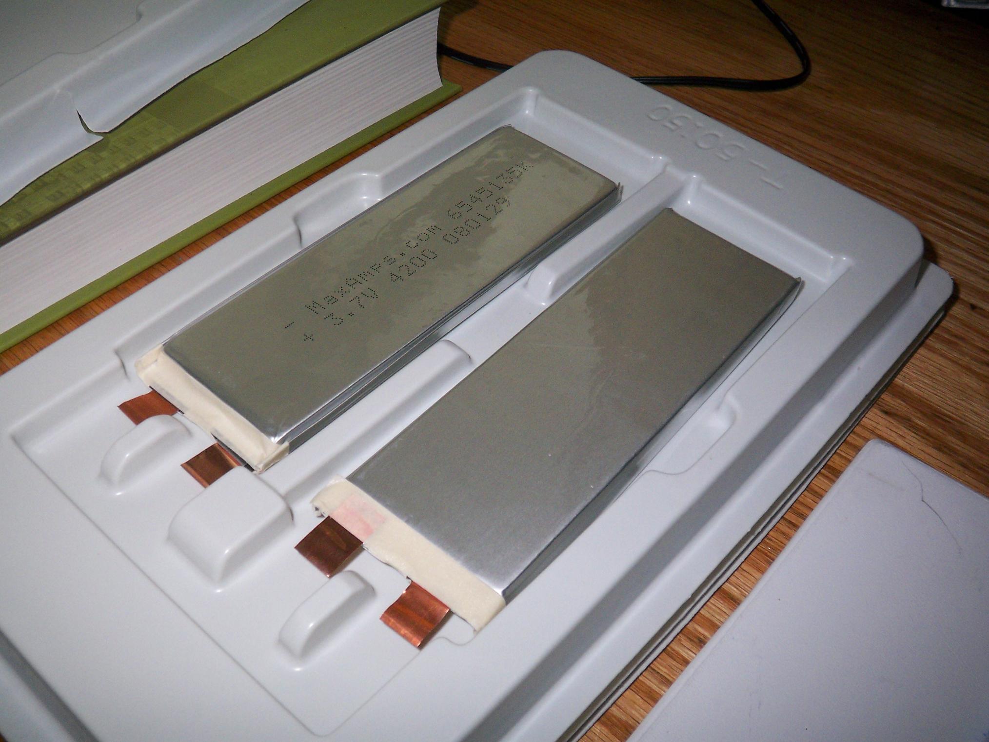
It’s time to address the electrical system. Here’s some 4,000mAh LiPo flat cells from Maxamps, courtesy of the folks at the Media Lab. According to Maxamps, they’re good for at least 80 amps continuously. If I ever draw that much current continuously, I’m making a large smoke cloud with it. I currently (PUN!) have 6 cells for 22.2 volts.

Curiously, Maxamps doesn’t quite explain how 80 amps could be drawn through a little aluminum flashing tab. Yes, one of the tabs is actually aluminum with a copper bit spot-welded to it. Whatever, if it has worked for everyone else…..

Trouble alert.

The 3 cell stack doesn’t fit by about .5 millimeters. I wish I were kidding. However, I knew this would be risky business.

Most LiPo cells of this capacity are around 5.5mm to 6.5mm thick, with the thicker being the higher discharge-rated ones. Maxamps advertised their cells as 6mm thick, which, in a 3-stack, left me less than 1 millimeter of play inside the scooter’s 19mm tall internal channel. The original battery mount was going to be “bottomless”, with the supports for the cells coming only from the sides and the bottom capped by a wide tape, such as fiberglass strapping tape or Kapton tape. My 3S pack with 6mm thick cells (which is not high discharge, unfortunately!) did fit in a test.

However, these cells are actually the 6.5mm type. I won’t blame Maxamps despite the fact that it’s printed right on the cell: “6545135” indicates a 6.5 x 45 x 135mm cell; beecause designing a battery mount to such tight specs is not very wise anyway, considering wires and heat shrink and tolerances have to be accounted for.

The result is that 3 * 6.5 = 19.5 which is more than what a snug fit would allow.

So naturally it’s time to deploy the backup plan.

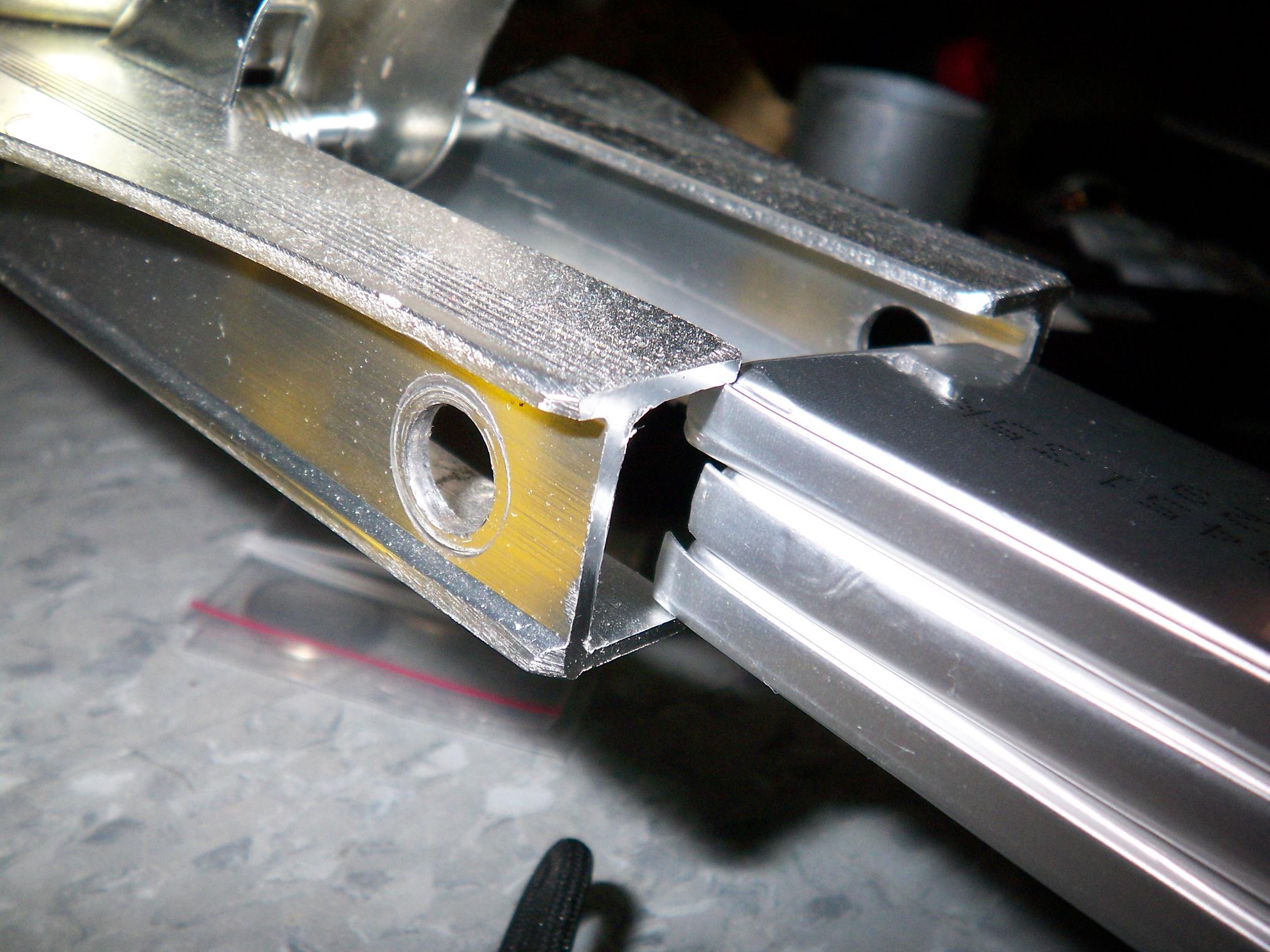
Here’s a sample section of a Razor scooter chassis. It’s a one-piece extrusion, which is great for mounting stuff to. The part above the flange (which is actually the underside, if you can’t tell from the scuffs) is 63mm side with a 57mm inner width.

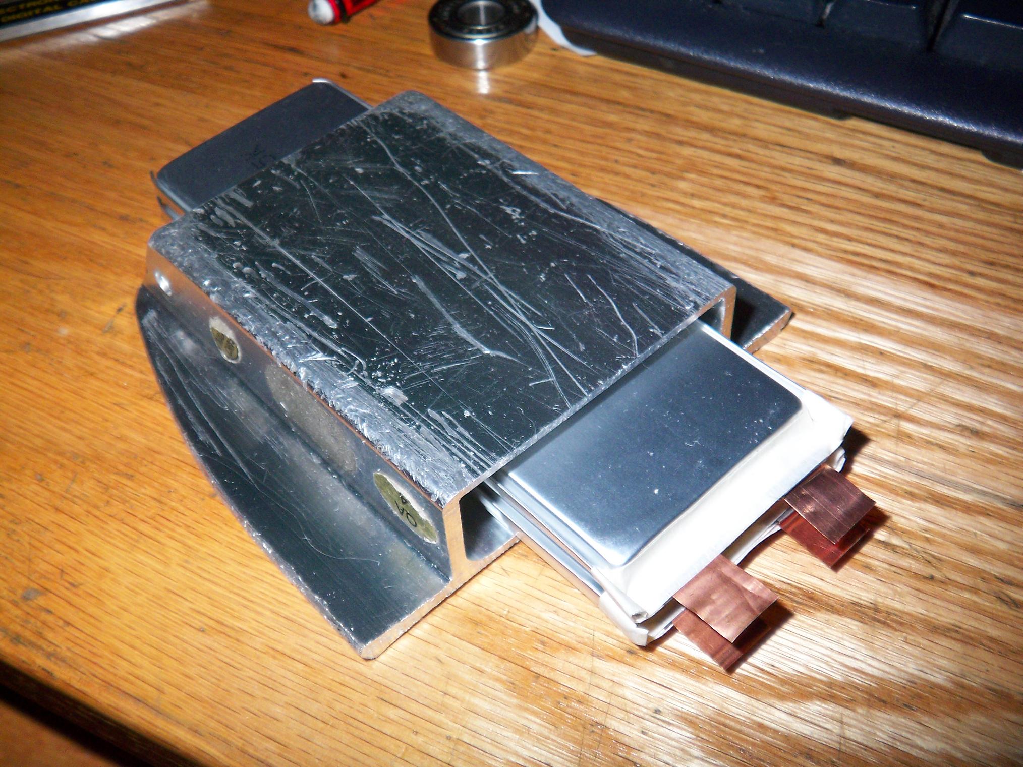
Two of the cells stacked give ample clearance for a proper internal mount. Conveniently enough, a regular Razor scooter has enough material between the wheel mounts to hold 4 cells, 2 stacks of 2.

Here’s a rendering of the hypothetical underbody battery pack. The original plan was to use 6 cells mounted inside the body with an optional 6 added on in series on the underside to more run time. However, I have also considered just running one 8S pack split between the internal channel and the external mount.

So the plan is to take the long section of chassis, mill off the flanges and one long side, then make mounting ears that slip onto the underside of my frame and screw in place. I lose about 0.6″ of ground clearance by doing this, which is as low as I want to go anyway. Going this route with only 6 cells isn’t worth the effort, and so I will buy 2 more cells from Maxamps.

The charging port and balancer will probably be located in this secondary channel, since I’m free to machine it however I want.

But wait! Why do all this work to the chassis of another scooter when I could just use plain aluminum channel?!

…because they don’t make 63mm channel, sadly enough, at least not where I can get it readily. The only channel close in dimensions to what I need (that I have found so far) is far enough such that I can’t machine the walls down and maintain structural integrity.

Besides, there’s a junked scooter that’s exactly the size and shape I need.

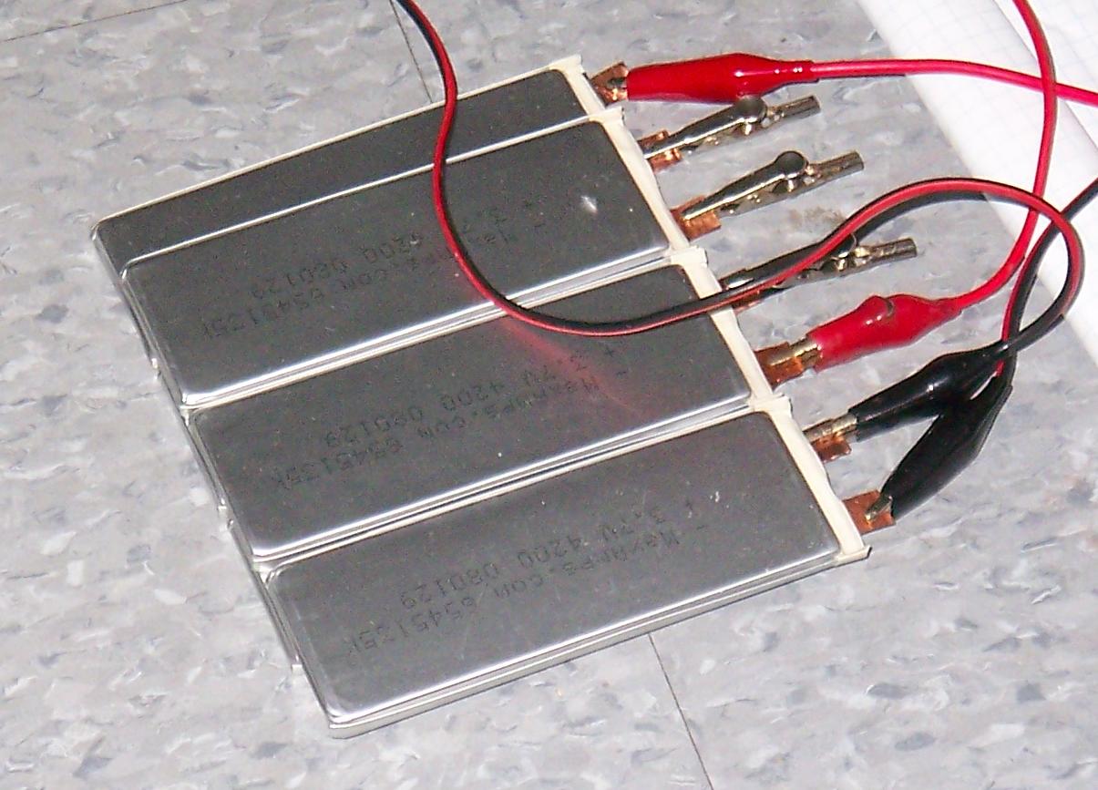
Hey kids, this is how NOT to wire up lithium batteries!

The first test run of the motor was on 36 volts, off Snuffles I’s pack. I tried a test using only 22.2 volts, and the motor was rather sluggish, and rightfully so. 8S will be advantageous in this situation anyway.

Now that things are actually wired up and moving, it’s time to make the mechanical mounts. I hope that I can get a test drive in before summer…

Bawt on?

Snuffles Reloaded: Update ∫f(t)e^(iωt)dt

Oh man, it’s ALMOST THERE! Spring break was too short, or else I partied too much at the Media Lab. Either way, OH MAN, IT’S ALMOST THERE! Build pics from the past few days…

So, to make the motor endcaps, I had to perform some slightly odd machining. The endcaps are dish-shaped, which would have been simple had there not been a lump in the middle to house the axle bearings. In order to make this lump in a dish, I needed to plunge cut into the face of the dish by about 2 millimeters.

This was a simple enough task when I had access to an awesome shop full of precise machinery and tooling out the nose, since some careful boring bar work took care of it the first time.

Unfortunately, I only had my not-boring-bar. Despite my best attempts at grinding the proper angles to let it plunge cut, and trying to align the toolpost to my best ability, it still sucked ass. I decided to wait until the building was vacated to keep working, since although the tool did cut, it made a 9000+ decibel high-pitched squealing despite all attempts to quell it. So there’s a very good reason I waited until 4AM to finish these things…

And so above is a picture of the First Attempt. All I had to do was make a trench big enough to stick a real tool in, or use the Not Boring Bar like how it’s supposed to be used (which is how…?). The outside is decent, but as you can see, the inside surface is horrific.

A quick run-through with a pointy tool solved the problem, however. It turns (hehe) out I cut a bit shallow, but fortunately, the custom-ground HSS bit could face cut a few hundredths and clean the inside corners to boot.

Flipping the thing around to bore the bearing cavity. As usual, it was ghettocentered with additional assistance from a stack of milling parallels jammed between it and the chuck. This insured the stator against being completely off-axis from the can and blowing things up like it did on the previous wheelmotor’s first build attempt.

Done. This is what I call a “Loctite finish”, which is when the finish is so smooth and accurate that whatever is being mounted slips in with a modest push of the thumb. With some green Loctite (I prefer 609 ultra-thin retaining compound) in the mix, the part will never come off again.

Ever.

(BTW, I lost the above image twice due to WordPress’ curious habit of making “undo” remove everything you’ve done for the past 5 minutes….)

And so with lessons learned from the first part, the second part was much, much smoother. I ground one of the 60 degree threading tools with a rake and side clearance angles so it could take the plunge smoothly. The procedure was to plunge cut, then move the tool in and out radially, making a wide slope-sided trench, feeding in more with each pass. When the sloped sided trench had been cut to the proper depth, the not-boring-bar was used to square off the corners.

The last step was to trim the diameters and cut the odd taper to mate with the scooter wheel. The diameter downsizing was smooth, the taper was not. There’s one downside to machining on low sleep reserve – you also have low common sense reserve. It would have been greatly smoother if I had set the compound slide at an angle and fed it in and out, like how you’re supposed to cut short tapers.

But instead I angled the tool itself and brute-forced it. Chattery results clearly shown. The dimensions and such are acceptable, but the finish is total bullshit. I slid some sandpaper over it to try and redeem myself, but decided it wasn’t worth the effort.

It’s on the inside of the wheel anyway….

Hey, it’s the 100th build picture of Reloaded! I have a habit now of documenting every little process involved with my projects. This is good, I suppose. Too bad the 100th picture can’t be of a finished product.

Instead, it’s of the magnet can. There will be 14 magnet poles (7 pairs), each of which is composed of either 2 or 4 mini-magnets.

Permanent magnets really love to 1) stick to eachother when you don’t want them to and 2) repel eachother when you want them to stick. Hence, I couldn’t back the mini-magnets up against each other. Instead, I had to place 14 “keystone magnets” first, at the proper angular displacements, and make sure they were firmly in place.

Thin CA wicked into the gaps between the magnet and the can held them in place well, and was also more convenient than making a mess with epoxy. I printed a 1:1 template from Gobrushless to help with spacing the magnets. When I’m happy with the magnet arrangement, I’ll lock them in with said epoxy.

The round aluminum piece in the background is the original “failed test piece” which I turned into an axial spacer for keeping the magnets the right distance from the ends of the can.

14 metamagnets composed of 2 mini-magnets are installed.

At this point, I wasn’t too sure whether or not to proceed. 28 magnets around the edges give me a near-perfect filling. Unfortunately, this is actually disadvantageous to an extent, as past a certain field strength, core losses start increasing and efficiency suffers. On the other hand, I stand to drop the voltage constant of the motor even further, making a slower, and hopefully torquier motor. But only 14 magnets gives rather poor filling. If these were, say, 10mm or 15mm wide magnets, I wouldn’t complain.

Intermission! I took the advantage of having my fingertips covered in a thin layer of CA glue to wind the core. Here’s one phase completed. The winding is “distributed LRK” style, with two-stranded 22 gauge wire looped 24 times around each pole.

Unfortunately, even with CA-shell assistance, I still do not have Manly Engineering Fingersâ„¢ and doing this took quite a bit of skin off both of them. The stator was mounted on something solid so I didn’t have to hold it, but pulling the wires tight did me in enough. I need to go find some gloves or something.

So I gave in, and shoved the rest of the 28 magnets remaining into the can. Bryan, you can kill me later. I promise. Just let me get one test run in.

I had 56 magnets exactly and couldn’t stand ruining my circle. How’s that for vanity?

Additionally, I decided to designate one of the endcaps as a permanent mount for the stator. Currently, the piece is on the radiator with the epoxy setting. Why?

If you have ever pulled the can off an outrunner motor (or yanked the parts of any permanent magnet motor apart), you know the magnets are very much attracted to the iron core of the rotor. On largeish outrunners, this force can be significant. On this fucker, it’s insane, and I’m going to make a jig to mount the stator without killing myself. The first time I brought the stator near, it nearly sheared off my finger because it flew so fast into the center of the magnet ring. The only way I could get it back out was pushing on the stator as hard as I can while gripping the can. And then it wouldn’t just fall out, because it kept getting sucked back in…

Hopefully, with some überpoxy holding the can in the Designated Endcap, I can bolt this endcap onto something, say the bottom end of an arbor press, attach the stator to the ram, and slowly drop it in.

This must be why permanent magnet motors aren’t made too large.

Anyways, stay tuned for the last few updates, which should be coming soon, assuming I grow new fingers by the time summer arrives. It’s almost moving!