The Turbulent Rise of Chibi-Mikuvan

After much engineering ado, it’s time for tiny van shenanigans!

This test was the first done with the NiMh modules from the Ford Fusion battery whose construction was detailed previously. I’d say subjectively the pickup is as strong or even stronger because of the added traction of doing it outdoors, coupled with the much larger wires (no more 12 gauge and Deans connector bottleneck) of the LiPo test pack. However, since I don’t have (yet) a Wattmeter-to-150A-Anderson-Powerpole adapter, I haven’t metered it proper. I do know that indoors, I’m traction limited at 3600 watts (as in no matter how hard I gun it, the rear wheels will just slip, leaving a thick trail of itself on the waxed linoleum hallway floor and making the reesarch center administration murderous).

One of the potential plans is to get a Cycle Analyst digital dashboard system or similar. Or, since I already have processing power in the back, and the salvaged current sensors from the Fusion pack, to just make my own.

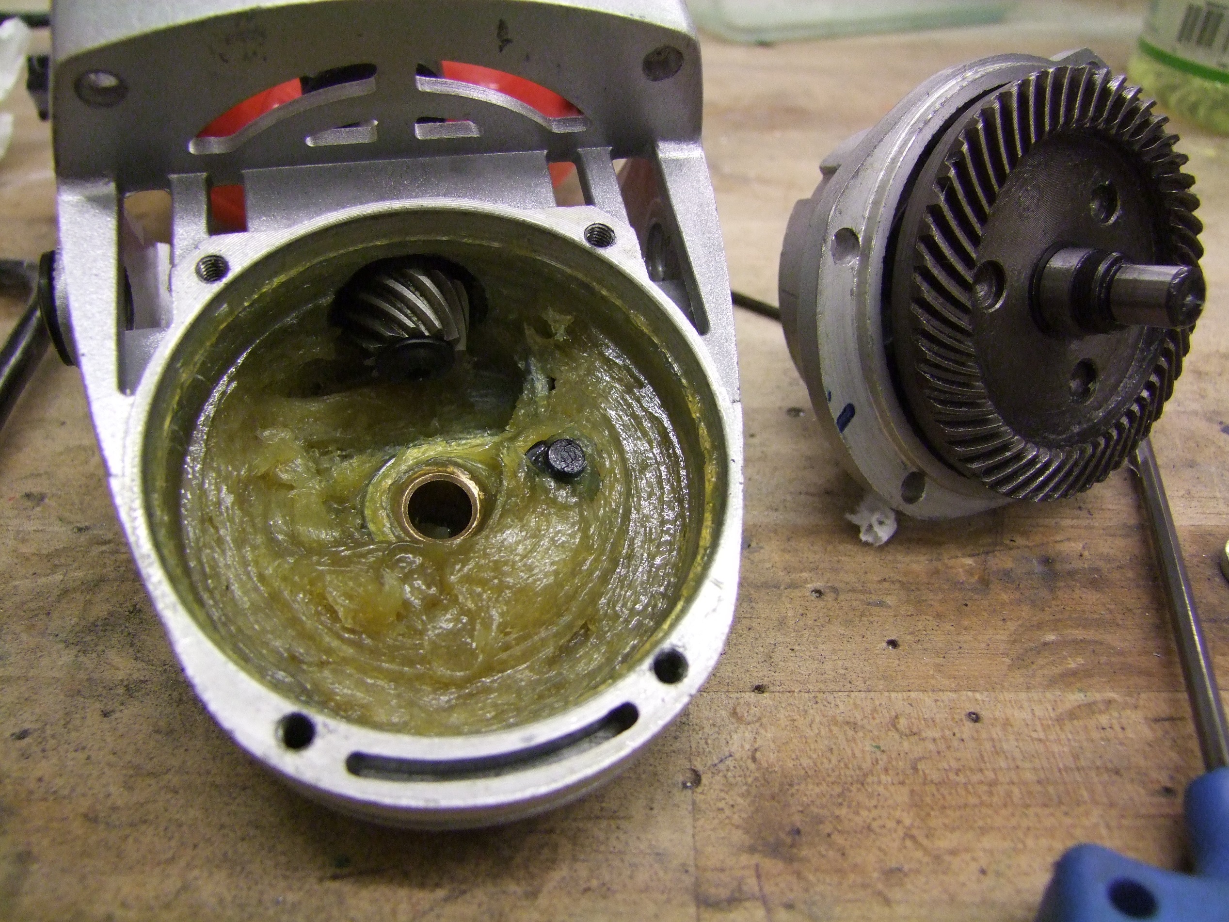
The terrible sound at 0:47 was the pinion of the angle grinder gearbox slipping its taper seat, unscrewing itself, and then falling off. It continued to jiggle and tumble in the gearbox as I pushed everything back upstairs. It’s now repaired – I didn’t torque the locking screw properly the first time because it’s in a hard-to-access spot where a regular hex wrench couldn’t get to.  After this experience, I cut down a standard L-shaped hex wrench until the short leg did fit.

To complete this round of build details, here’s the last bit work on the battery pack before the outdoor test.

After adding the tie rods to hold the endcaps together, I decided that an intelligent thing to do would be to make an easy way to lift the battery with one hand. I used the left over black 1″ wide cargo strapping which was part of the ratchet strap holding the electronics deck down, along with some rivets and washers, to make a handle. This worked out great, and I have enough of the strap to make 2 more batteries at least.

This is how the battery mounts in the frame, with the two knobs on the sides. Since this is a less than half sized battery from the original design, and the two knobs up front are directly opposite one another on the same axis, the pack can pivot forward and backward right now if the knobs aren’t super tight. Clearly not optimal. I’ll probably just resolve this by adding two bars to the front and rear of the battery pack, such that once dropped into place, they can no longer pivot.

Once I confirm that design, I have enough modules from the Fusion battery to make three more spare packs. The knobs allow the battery to be dropped out quickly, so having a ton of spares on charge during a PRS race makes sense.

And a “press shot” outside in the parking lot.

What’s missing at this point is the water cooling system for the Trackstar motor.  After the numerous high-power takeoffs during the test, the motor was hot but not unhappy hot – I could still hold onto it. But, it’s clear to me that if I want to run above 1000 watts for a long time, it’s going to need the water cooling loop. This will come after the 2.00gokart race when things quiet down a little bit.

It also doesn’t have the wye-delta switching contactor assembly I wanted to incorporate, but I’m of the opinion that the speeds attainable by the Delta termination is utterly unnecessary for an event like PRS. The project top speed under this condition is north of 40mph, which is a domain already well optimized by, like, real Mikuvan.

Here’s the final details…

Cheat Sheet

Motivation

I started this project as a museful distraction in October of last year after returning from the New York Maker Faire and mingling with the Power Racing Series folks for the third year. Having seen the league grow immensely, I decided to finally enter something while exploring new and unusual components for hobby builders (my usual MO) while also wanting to see a change away from the “model year bloat” I saw in many teams, who started using heavy forklift motors and other salvaged industrial components. Hence, the focus on R/C electronics and non-lead chemistry batteries.

Work on the project began more in earnest with this season of “2.00gokart“, since I figured I needed to have an instructor vehicle to troll my own students with.

The project was my first jump into making a composite bodied anything, motivated in part by the bodywork repair I’ve had to perform to real-Mikuvan.

Build History

In chronological order up to the previous post, here’s the process of Chibi-Mikuvan creation from conception to implementation:

Naming

The project is named Chibi-Mikuvan after its principal design predecessor, the Chibikart twins which were the “prototypes” for the design class I teach today, and my 1989 Mitsubishi Delica known familiarly as Mikuvan.

It has little to do with Chibi-Miku-san though a few large decorative decals would not look out of place on the shell. I’m an avid follower of the crowdsourced synthetic Japanese future girl-pop that you’ve never heard of world of Hatsune Miku and Vocaloid. That’s literally the most concise way to fully describe it, as I have learned over many difficult discussions about what the inglorious shit is it that’s playing all the time in my shop.

Components

Specification

  • Top Speed: 25mph (as-geared, Y-termination)
  • Acceleration: to 25mph in < 3 seconds
  • Braking distance: < 30ft from top speed
  • Skidpad: Uhhh, gimme a sec.
  • Clearance: Still not enough for the Maker Faire cable protectors
  • Drivetrain: RR layout, 1 speed, spool axle (no differential)
  • Dimensions: 50″ L, 28″ W, 24″ H
  • Weight: 113lb with battery
  • Seats: 1, though if Chibikart was any indication to go by, up to 7.

Bill of Materials

Here’s the latest iteration of the BOM (5/1/2014 version), which contains at least 95% of everything on the thing, short of the trivial like zip ties. I went into much more detail than the average PRS list; the quality is a little more closer to what I expect out of my students when it comes to found parts and used parts. Everything, to the degree possible, is given a Fair Market Value which sort of artificially inflates the cost a little. While technically over the PRS $500 statutory budget, I believe this is a more realistic representation of the cost needed to replicate this once.

The BOM has 3 cost categories. First is the actual money I spent. I had a fair amount of parts already on hand, but did have to buy things full-price like the Ford Fusion battery pack and the motor & controller. Next is the PRS rules based accounting, exempting some things like brake parts. Finally, what this vehicle would cost under my 2.007 EV Design class rules, where some raw materials are provided to the students so they only need to count materials if they need to be purchased additionally.

Future Work

I plan to finish building the water cooling rig in the coming weeks, as well as play with the nice automotive-grade Hall Effect current sensor salvaged from the Fusion pack. For the telemetry/dashboard, all I’m really interested in is instanteous volts, amps, watts, and cumulative watt-hours spent, and all of that info can be gleaned from a voltage sense (easy) and current sense (also easy with the sensor). I do need to build more battery packs, and create or buy a dedicated Giant NiMH Battery charging solution. I have a Hyperion 1420i charger that can blitz into this pack well, but having more chargers would be essential in a race scenario.

Also, make more silly magnetic stick-on anime faces.

And as usual, some fun times in our proving grounds, the spirally garage:

Chibi-Mikuvan Intensifies: Mechanical and Electrical Updates

As the 2.007 Silly Gokart Race draws closer (by which I mean it’s this weekend), so does the completion of Chibi-Mikuvan. Since last week’s outer shell work, I’ve brought the frame to mechanical and electrical completion, and have tested it under power. Technically it’s now “internet-complete”, which is a term I defined to mean that a project is finished enough that the Internet wouldn’t know the difference. It’s like “internet famous”. Here’s the somewhat chronological recap, as usual – a few things didn’t happen in a purely consecutive fashion but it’s much easier presented that way.

While the layers of resins and paints and the like were slowly crosslinking, I returned to working on the drivetrain. I last left it in a state where the frame could roll around, but the motor wasn’t mounted to the angle grinder gearbox yet, nor did I make the adapter shaft for it. I had planned for the angle grinder gearbox shaft to be keyed and for the pinion gear itself to be broached, but that would have necessitated buying a 10mm bore bushing for a 1/8″ (or 3mm) keyway, which was also nonstandard. What? Hell, if I haven’t remembered to make or buy the bushing by now, it’s clearly never happening.

That same day when I pulled up the design files, I decided to abandon the keyed shaft and return to something I last did in 2005 with my old 12lber Trial Bot: a tapered shaft and matching tapered bore. Tapers can transmit power with full material contact instead of relying on several small, discrete fastening elements like a key or set screws. They can be the strongest coupling method per volume because of the full contact and least concentration of stress.

The idea would be to machine a certain taper into the gear, machine the same but slightly shorter taper into the shaft, and then mash it together with a fastening screw. I chose a taper angle that would be self-locking to prevent the screw from having to hold rotational torque – this implied a taper of less than 10 included degrees. The design constraint here was that it had to start at 10mm diameter, end at 12mm diameter, and do so in the space of 17mm, the size of the gear.

Well that turns out to be 6.75 degrees, so I just rolled with it.

Shown above is technically the finished product – the gear on a tapered bit cut into a 12mm piece of precision-ground shafting steel. On the other end is an 8mm reamed hole to fit the motor shaft. I then took this scrupulously machined shaft and repeatedly hacked it up with a Dremel to make the clamping slit…. precision!!!!

To make the taper, I decided to exercise Tinylathe. I set the compound to as close as 3.4 degrees (roughly half of 6.75 degrees) as I could, and busted out one of my old miniature carbide boring bars for the job. The pinion steel was tough, but clearly not hardened, so this step ended up being much easier than anticipated.

The angle grinder gearbox made axial alignment of the pinion easy, since by default it’s just rested against the bearing. Spiral bevel gears are supposed to be very high precision devices, but I’m not so sure about these.

After assembling and closing everything up, here’s what the gear drive looks like. The sprocket has a big notch milled into it to interface with the spindle wrench flats of the angle grinder gearbox. The big nut is just to keep it in place axially, and it will be replaced by a smaller, more mild-mannered nut.

The coupling to the motor is done by tightening a 12mm shaft collar over the split section of the adapter shaft. This is a method I’ve used many times when one shaft is larger than the other, and is very simple to implement – drill an axial hole, then slice with a Dremel (or more legitimately, a slitting saw)

With the drivetrain basically done, I began plotting what to do about the electrical system. I was going to just lay out the contactor deck salvaged from the Ford Fusion battery on a piece of plywood or hardboard and lay the other components next to it for starters. I decided, though, that the three contactors on that assembly were just totally overkill for the end goal – I have no reason to need a precharge contactor AND discrete battery positive AND ground isolating (battery negative) contactors. Really all I need is a single positive side contactor with the precharge system built in on it.

Once the stock contactor deck was out, I began getting creative with the packaging. It occurred to me that I had several 7.62 NATO ammo cans which fit very well in the rear box frame. This was a complete accident, but a satisfying one. The ammo can could fit all the components and keep them water and splash resistant, since every year at the New York Maker Faire, it somehow rains. I took a while to arrange the components in a manner which made sense.

I decided to pursue a vertical solution with two levels, keeping the big power on the bottom and the signal interfacing on top for easier access. This is, of course, all predicated on the reliability of the power components, the Hobbyking motor controller in particular. In the design above, though, it’s still not too hard to get out if needed.

I left a large gap on the right side, by the ammo can’s hinge, so I can put the Hella master cutoff switch in the area (it sticks down pretty far) and a fuse block on the outside to make the mandatory fuse easily accessible.

The white component in the design is an “isolated ground stud”. I elected to use this method instead of a large terminal or bus block because of the limited number of ground connections I needed – basically one big wire in, and one big wire out. I remembered using these in FIRST Robotics before the power distribution became all fancy and modular.

The ground stud itself is a custom 3d printed job using a Makerbot, with a broken Hella switch’s terminal inserted through the bottom as the stud.

The first step in processing the ammo case was to remove the handle to make way for the switch and fuse block. I drilled the spot welds out to remove the handle anchors. The cutouts for the Hella switch and fuse block were made with a Dremel cutting wheel.

The Hella switch is now installed along with the mini-ANL (or MIDI, depending on who you buy it from) fuse block. I designed some wire guide/grommet/panel mount things which are installed into their own cutouts on the sides. These were designed with three tiny holes which I could drill out to fit different wire and cable sizes. They’re split into two pieces so they can install over a wire I thread in first, instead of having to deal with pre-installation, which makes the whole system more flexible in case I change something. Remember, this was practically designed on the fly.

Laser cut MDF lower deck with power components installed.

I prepared some auxiliary components, including the 12V rail supply and the precharge resistor. The 12V supply is a chopped up 5V R/C BEC unit like eNanoHerpyBike’s – I have a pile of dozens of these things, so it’s easy to grab one and go. The primary 12V consumer will be the roughly 0.9 amps needed to supply the contactor coils, and a very small amount otherwise running logic and fans.

Installing the first deck now. In this design, I chose to have the DC/DC unit pull power from ahead of the precharge resistor. What this implies is that the 12V and logic systems are powered on as soon as the Hella switch is turned on, ensuring that the logic is in a deterministic state before the ESC wakes up – the precharge resistor causes a delay in its turn-on since the voltage fed to the ESC rises slowly. Subsequently, if the contactor is opened for any reason, the power to the  ESC is soft-killed while the logic power remains on.

The second deck contains a 2.007 Arduino breakout board and a terminal strip to make outside-world connections with. The 2.007 board is currently only being used for its Arduino Nano, though the breadboard opens the possibility of adding some more custom signal processing circuitry, if needed.

I cut out a MDF plate that closes of the bottom of the box in the rear portion of the frame. It has two slots to allow the use of a small ratchet strap to hold the entire thing down. Perfect fit!

Here’s a profile view of the go-kart side of things. Overall, the setup is fairly clean and all of the powertrain is confined to the rear.

And yeah, that chain needed tensioning. I ended up using a half-link (example) to shorten the chain just enough that the slotted mount of the rear bearing blocks were enough to take up the rest.

In this configuration, with a makeshift 7S lithium polymer battery jacked into the massive 150A Anderson powerpole connector, I rode it around to test the Trackstar controller‘s startup response. As with all sensorless R/C starts, it was jolty, but the controller is smart enough to slow down the open-loop forced commutation frequency if it detects a no-start (cogging or “pole slip”) condition, then try and ramp up from there. It’s clearly designed for ground applications.

With the very high gear ratio present in the system, it’s able to take off basically within half a second of applying throttle each time. If the motor lands in an unlucky spot, it does cog, but recovers quickly.

I do want to use the liquid cooling feature of the Aquastar motor, so I had to sequester a water pump and radiator from somewhere. Luckily, a MITERS member had a spare cooling rig from an old PowerMac G5. I would just need interconnecting tubing and a little jar as a reservoir.

Power Mac G5 liquid cooling pump pinout

It took me a great deal of Internet wandering and the sacrificing of one of the pumps to find out the pinout of this connector. So if you don’t get this information anywhere else, here is the pinout of the Power Mac G5 liquid cooling pumps, the kind with the 6-pin connector. Did I mention that this is the pinout of the Power Mac G5 liquid cooling pump with the 6 pin connector? By the way, this is the pinout of the Power Mac G5 liquid cooling pump with the 6 pin connector. I even added image descriptions to the image itself saying that. Google is about to delist me for black-hat SEO, I’m sure.

To turn the pump on, ON must be connected to the 12v rail. It’s a very quiet centrifugal type pump.

I put aside the pumps for the time being to finish the last bit of visual detailing for the outer shell. I’m not going to be fancy and add working tail lights (yet), so for the time being they’re patches of orange and red paint. I basically reused the “inverse stencil” method again, covering the area in masking tape and knifing away what was not needed using the drawn lines as a guide.

Here’s the taillight painted details with the first bumper sticker! Okay, Beantown, you win. Beantown Taqueria is the nemesis in my ongoing fight against obesity and heart disease, but a very delicious nemesis.

Moving back to the powertrain now, here is a set of shortened battery pack endcaps I machined. But wait! Wasn’t the battery going to occupy the entire floor area?

It was also going to weigh about 60+ pounds. I test rode the chassis while holding a 55 pound Class-D fire extinguisher, because I love being ironic and also because it was the most compact object to weigh that much. This was such that I could simulate the battery’s weight. Conclusion: The sensorless starting routine is getting really borderline.  Adding 60 pounds to the combined weight of me plus vehicle (about 70lb of vehicle and 150lb of me) is a 27% weight increase, and the gear ratio is no longer enough to guarantee starts!

Alright, so 1.0kWh of battery was going to be ridiculous. I decided to cut the battery to a third of its original size. In a PRS race scenario, I’ll have to run for at most 15 minutes between required pit-ins and driver change (in the endurance race format), so as long as the battery is quickly swappable, it should work fine. The new battery, 28.8v and 16Ah, will weigh only about 22 pounds.

Hence, I redesigned the battery caps to only hold 6 of the Ford Fusion modules, and mount by only two of the four mounting holes.

To make this battery, I started taking slices off the cake and rearranging the cells inside the module. Some of them needed to be flipped around in their casings, so the positive and negative terminals could face the correct way. I discovered that the rubber isolators that they put around the cells are designed to only fit in one way, so the casings could no longer close if I just flipped the cells. Those had to come off – they’re the rings to the right.

I reused the bus bars that came with the battery pack to make the interconnects. There are two modules in parallel per “cell group”, and 3 groups in series, to make 28.8V and 16Ah.

Here they are, stuffed into the endcaps as a test fit. There are some touches I have to add, such as, you know, output wires.

So this is the progress of Chibi-Mikuvan up until last night. I’m intending to have it running, maybe not liquid cooled, by Saturday’s 2.007 EV race. I also have half a mind to drive across the country to Bay Area Maker Faire (not driving it, mind you…) and enter in the first PRS race of the year.