The DeWut Motor: Next Steps, and Design Files for Making Your Own DeWalt 3-Speed Motor Mount

Alright, with the Long Weekend of Nobody Being Open coming to a close, I’ve pretty much finished the ‘version 1’ of this project and am moving onto another fork of it. As discussed previously, the DeWut is an effort to make the new generation DeWalt 3-speed hammerdrill gearbox actually useful. The ‘old generation’, according to my sources, has totally stopped production, and are getting harder to purchase spares for. DeWalt has been the foundation of so many robots I’m surprised they don’t straight up sponsor events.

The short story is that I am skipping over a waterjet-plate stacking version (… what? Are you out of your mind?!) directly to investigating an all-billet, CNC machined version. That seems a very not-me thing to do, and actually I’m going to build a few of the aforementioned waterjet-compatible mounts for my own amusement, but as a potential product, I am in the process of gathering quotes and potential suppliers.

The long story…

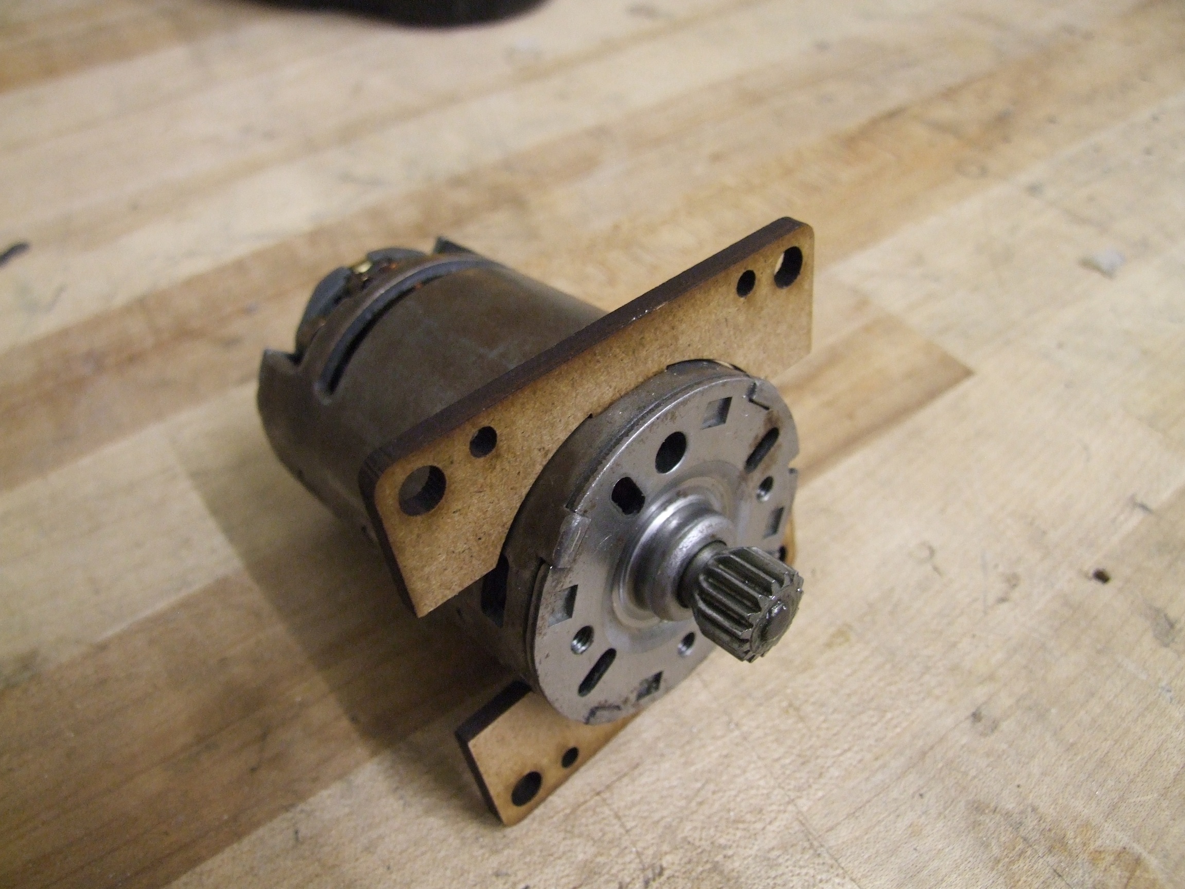
After completing the body of the first version gearbox, I went ahead and carved the future shaft out of some 1566 precision-ground steel stock. Luckily for me, the new generation DeWalt gearbox has a rather normal double-D shaped output adapter, so it was a short mill pass to turn the round shaft into the proper mating shape. Unlike the old style gearbox, which had a…. what the hell is that? Apparently a massive stress riser. This would be only a manufacturability test, because untreated steel is going to be far too weak to handle the torque output of the motor. Based on a few FEA torque simulations, to hold the torque of the motor at stall in low gear at 100 amps, the double-D area is going to see about 180ksi of shear stress.

Ouch. That’s some serious steel – comparatively few alloys can heat treat to the 200ksi+ range and not be brittle as glass, and we all know how my last adventure with “heat treating” went. This is a subject I’m not so familiar with and so will probably have to leave to the professionals when I make these into production parts. For my own amusement, though, I’m probably going to buy a sampler plate of steel rods, make the axles, and try heat treating the ends to various degrees.

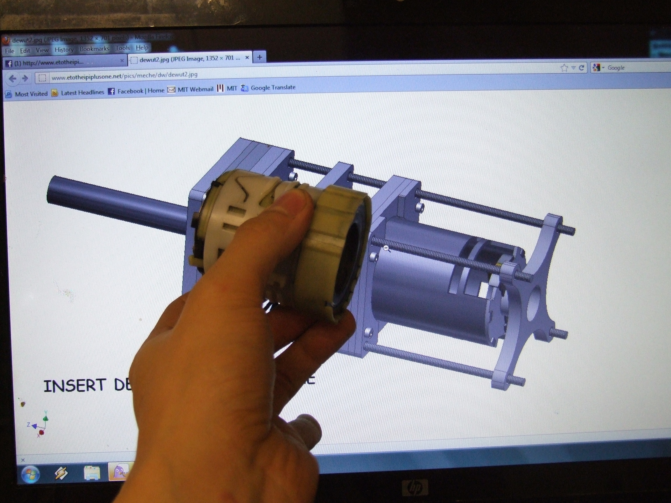
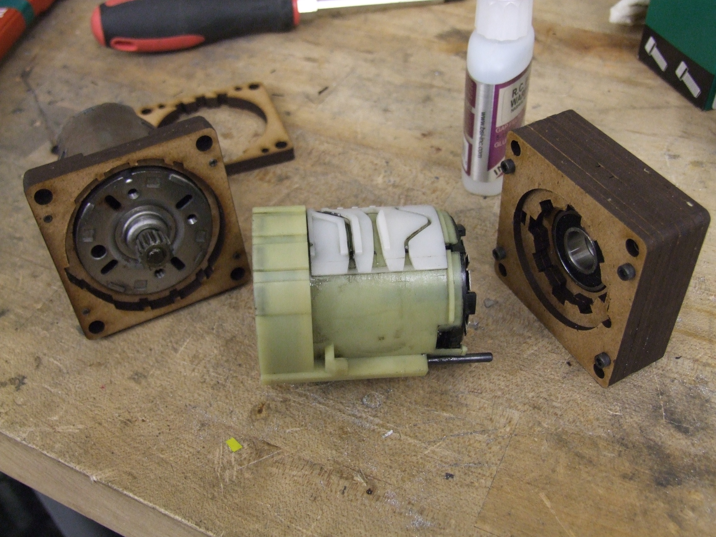
I also came up with a new arrangement for the motor’s rear retaining plate. Previously, it only held onto that little nub that the motor’s tailshaft sticks into, and was fairly unstable. A more stable method is enveloping the ‘nub’ and pressing entirely against the motor’s endcap. Unfortunately, the brush holders have conductive crimps that end flush with the endcap surface, but can still short on metal. Hence, a ‘gasket’ of sorts is necessary, shaped to the endcap’s outline, and I’ve modeled that as the little yellow-beige-brown thing to be made out of a thin insulating material.

Additionally, the structure of the Nifty Barrel Shifter retainer has changed. It’s now removable from the side and the idea is to hold onto it with a nut from either side. The bolt slotting narrow a little before opening up to the proper center, so it ‘snaps’ into place and is less likely to fall off. This arrangement makes it easier to change gearing (if needed) but also allows the whole thing to be assembled before picking the gear ratio, since it does not have to be stuffed onto the gearbox while it is being lowered into position.

But the most important addition conducive towards kitting this assembly up is the alignment marks on the side. Starting with 1 little indent slot on the side, just line the plates up in incrementing slot count order. I figure the X shaped motor back end is obvious enough on its own. There’s 9 in the structure, then the gasket, then the motor retainer, for 11 total.

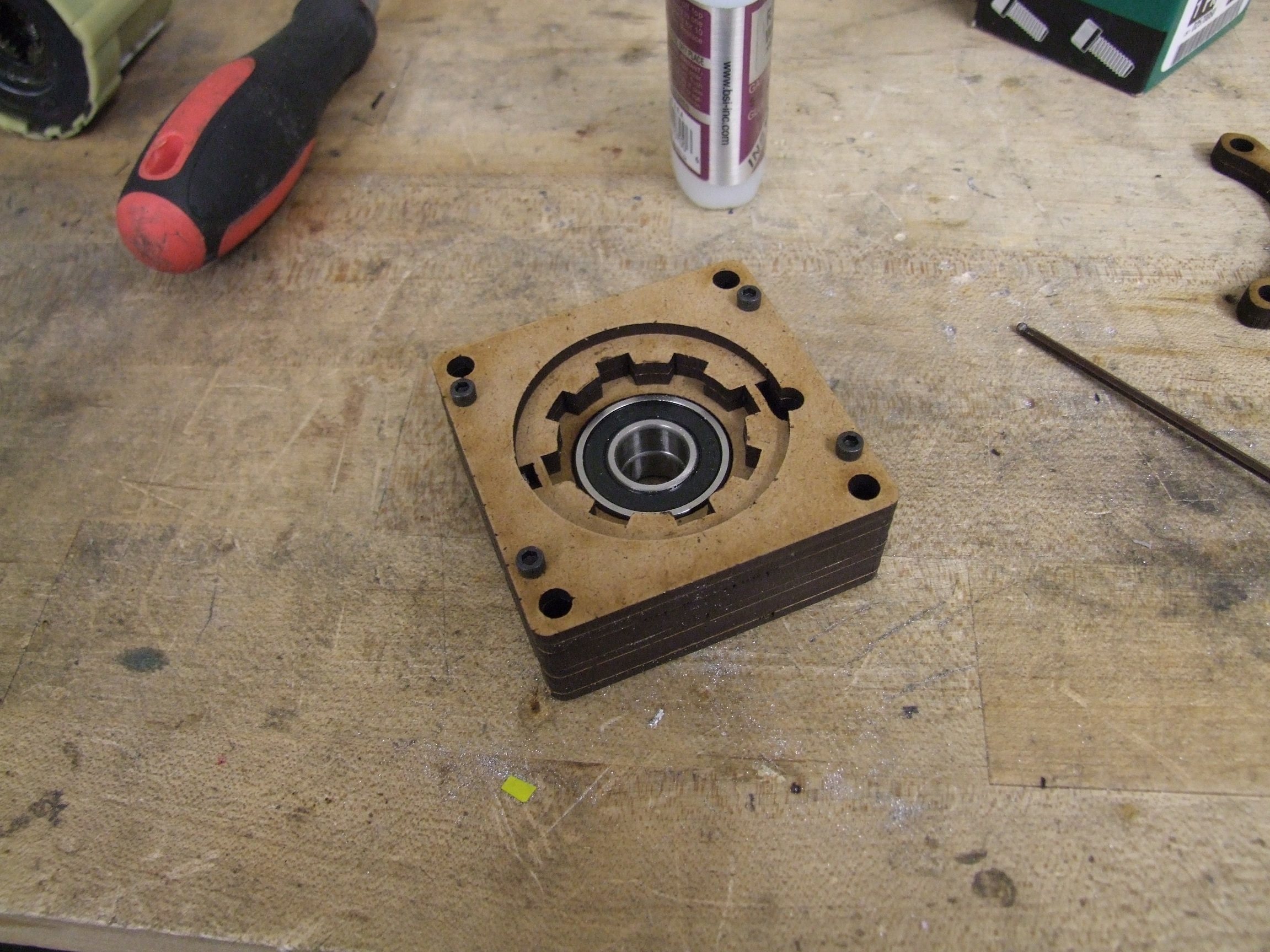
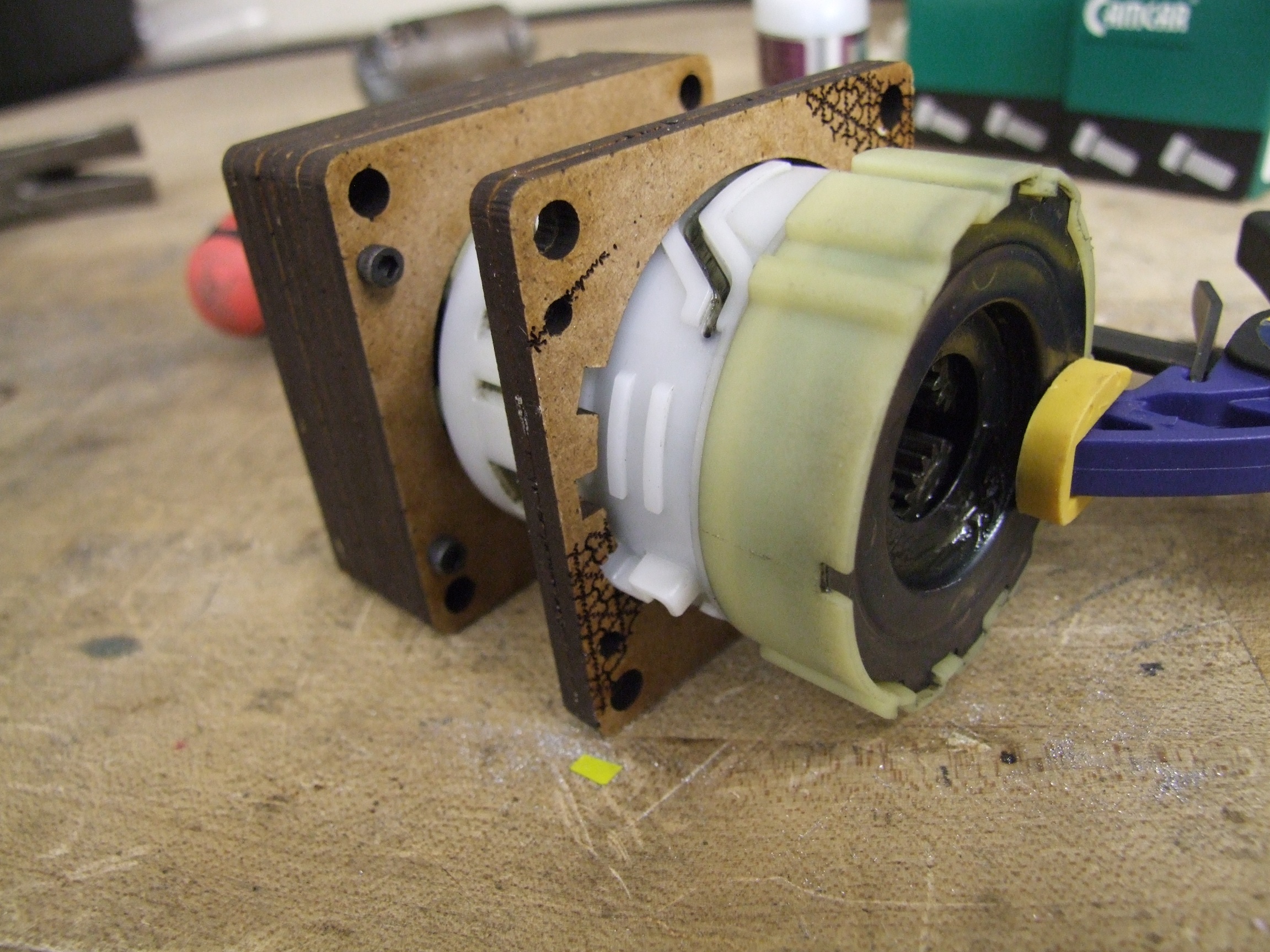
This is what the retaining plate looks like now. Of course, one option to bypass the need of a sketchy nonconductive shim which COULD conceivably become conductive by accident, is to make the thing out of a nonconductive material. Garolite (G10/FR-4 grade) was my prime candidate, but electrical grade fiberglass ought to work too. Anything in 1/4″ short of nonfiberous squishy plastics ought to be stiff enough to hold the motor in place.

Moving the retainer plate onto the motor endcap means the whole assembly becomes basically 6″ long minus the shaft length. A nice, even number to work with!

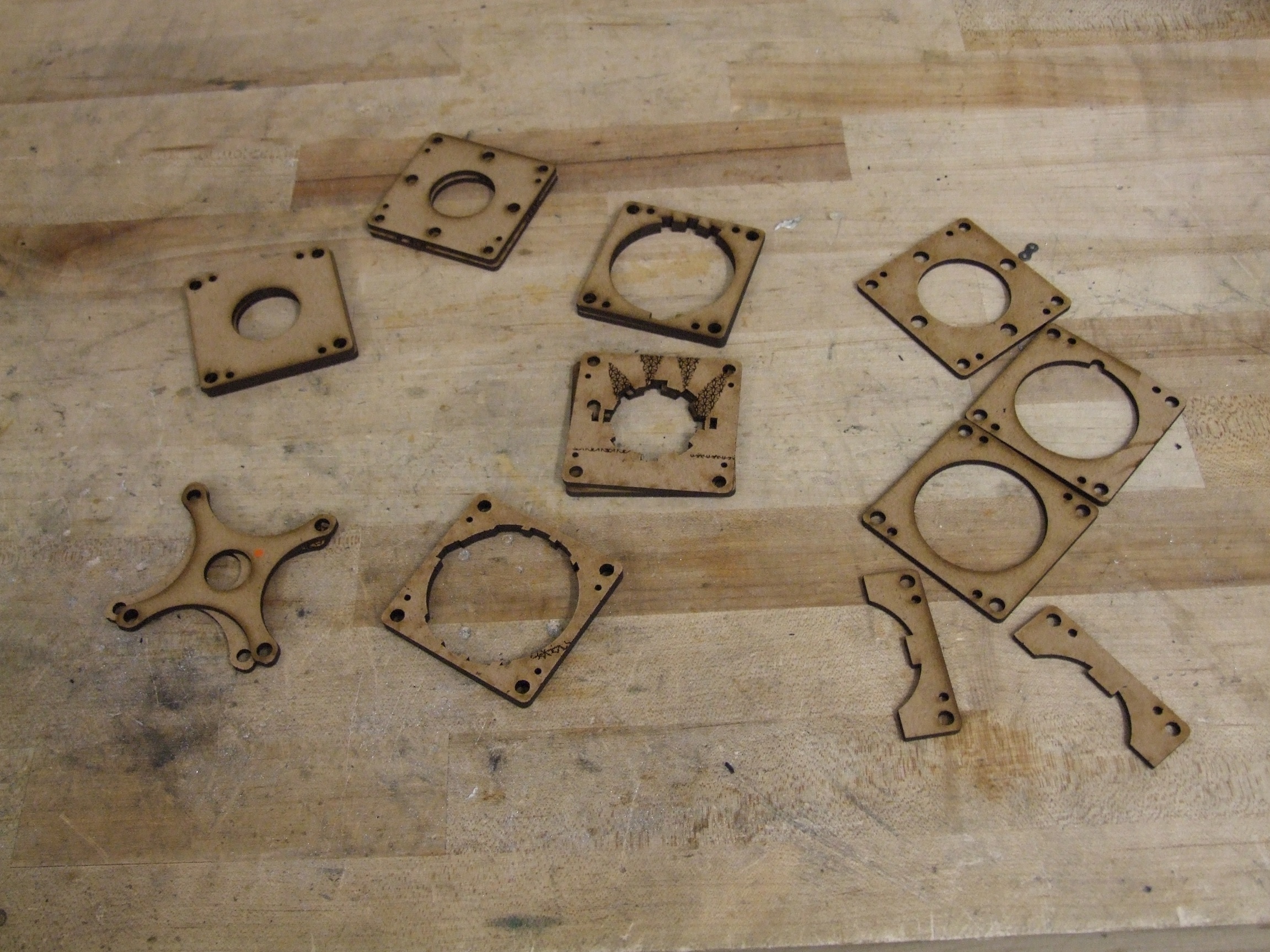
For the purposes of easy cutting, I arranged these plates into separate 1/4″ and 1/8″ assembly files with little “sprues” in between the plates. This ensures that they stay together and cut as one part, and can be extracted whole.  It’s a little more dangerous than individual parts, but machine time is billable by the second and precious seconds are spent cycling the nozzle, so continuous cutting is marginally cheaper too. For small parts, the sprues prevent them from falling into the tank.

However, I think that’s as far as I’m going to go with this design. Here’s why:

Huh. Well then.

That’s just for the 1/4″ parts! Note that I tiled 4 of the assemblies together, so the real cost is about $38 per set. Add to that the 1/8″ plates (another $20 per set) and the heat treated, custom machined steel shaft (estimating $30+ each), plus all the hardware and the laser-cut gasket. I’m basically looking at a hair under $100 just in cost. And only in quantities 10 and up, assuming I have like $8000 to drop on this right now.

As funny as modern digital manufacturing is, and as great as it is if I really just needed 1 of something, I think I can get a much better price by falling back to good ol’ subtractive machining. Hey, as it turns out, waterjetting in real life is expensive.

So, as previously mentioned, even though I could pop out a few for my own use, I won’t be able to introduce these as a viable product (in my opinion – feel free to differ). So what’s next?

DeWut? Design Files

I’m going to make everyone else do it. Contained in the above ZIP file is the two tiled parts to be cut (0.25″ and .125″ aluminum) and a 2D drawing of the gasket to be made from something nonconductive, in DXF version 2000. Also included are the original Autodesk Inventor 2012 3d models of the assembly and an exported version in X_T (Parasolid) which can be imported back into individual solids.

The assembly should only fit together one way, basically described in the first post.

There are a few #4-40 holes to tap in order to make blocks from the plates at first.

The mounting holes up front are properly sized to be threaded 1/4″-20, no more than 3/8″ deep.

The shaft solution, however, is left as an exercise to the reader (the shaft model is included).

The model as-cut should fit the new-style DeWalt transmissions (397892 series), possibly with a little stuffing.

There’s no warranty expressed or implied.

Next Stage

Based on my experiences sourcing the hub motor parts for Chibikart, I believe I can get billet mounts for the gearboxes contracted out through a Sketchy Chinese Dude With a CNC Machine for substantially less price. Leaving the thickness quantum domain also means I can make the gearbox mounts better fitting and have multiple threaded mounting holes, etc.

I basically began translating features found in the stacked plates into a single, solid model. There were optimizations for weight reduction made, as well as thicknesses and details changed to fit the manufacturing technology.

This is the end result. Now, it’s not totally free of potential laserjetted parts, because I’m keeping the Nifty Barrel Shifter holder. It will still rest on the tie rods that hold the thing together.

Check out that new motor mount. It’s a 2-piece clamp affair out of necessity because the DeWalt motors don’t face mount to the transmissions, they stick into them a good 1/4″ or so. Hence, the idea is to tighten together the gearbox and shaft portion, then stuff the motor in, then tighten the mounting collar. With a 1/2″ of support on the collar and additionally 3/8″ of support in the aluminum block, I think the motor’s not going to go anywhere short of having the output shaft shoved through it (by which time, terrible things have happened). This obviates the need for a rear retainer.

Overall, I’m looking at 3 aluminum machined parts, 1 heat treated steel part, and a derpy laser-cut thing. Because the NBS holder is not structural, I’m content with making it from Delrin or ABS plastic.

Incidentally, the mounting holes match a Banebots P80, at least on the front. This whole thing is basically a lighter P80 type motor with 3 speeds!

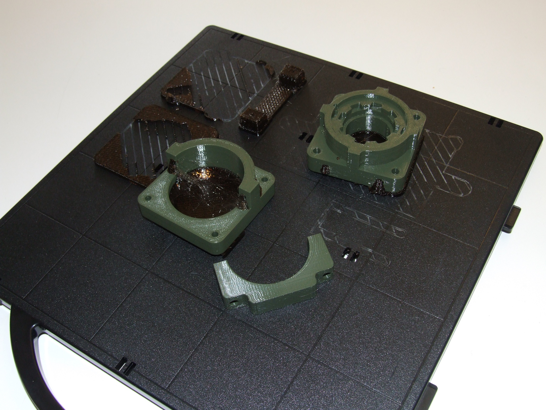
Of course, I’m not leaving the world of 3DRP forever. I wasn’t going to send anything out without a sanity check for the critical mounting dimensions. I turned, appropriately, to a Dimension 1200ES to produce these mostly hollow plastic shell representations of the gearbox. The Dimension printer is much better at making parts ….. on dimension…. than the Makerbot Flock.

Since it cost 3 times more than the aforementioned Makerbot Flock combined, I would expect nothing less…

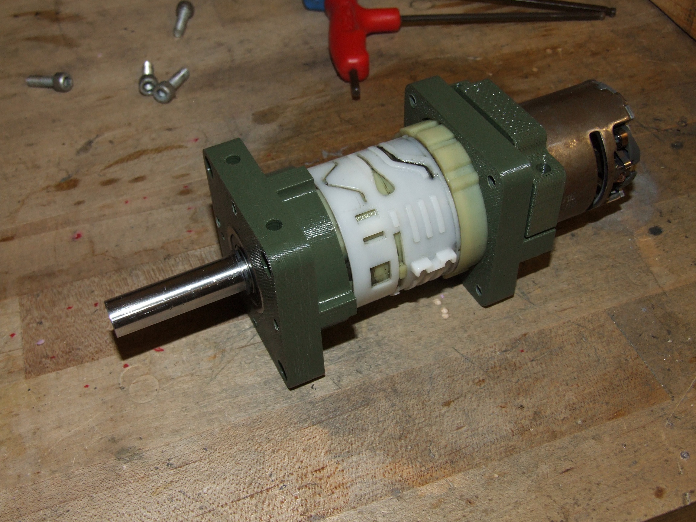
And hey, everything fits! I verified that the little slots and cutouts to cater to the DeWalt housing were within reason – if they fit in slightly shrinky plastic, then they will be a little looser in aluminum unless Sketchy Chinese Dude with a CNC Machine is really that sketchy. The overall length has remained essentially the same – this was basically a direct plate translation, after all. The Nifty Barrel Shifter holder is not seen in this picture, nor are the #10 cap screws that will keep the two halves firmly locked together.

The next step from here is to pitch all of these parts to my favorite SCDwCNCM as well as mfg.com (my new favorite snack) to compare prices vs. features. At this point in the year, I’m going to consider getting prototypes in before the holiday breaks a total not-happening, so expect some more news on these DeWuts in January.

By the way, this is what is inside an allegedly “empty” Stratasys Dimension ABS build cartridge.

…seriously? That’s like 50 feet. I only feel slightly ripped off.

Luckily, this filament is 1.75mm diameter just like the latest generation Makerbot Flock feed, so I’ve been making heart gears using the Replicator. Productivity!


The DeWut? Motor Project

With the Thanksgiving holiday weekend in full swing (read: nothing is open) and with RageBridge revision 3 boards still out for manufacturing (read: nothing’s gotten shipped), I’ve been shaking up the old random project idea jar a little for quick, useful things that I can whip out over the next few days. Here’s one of them. It’s been baking in mind actually for a long time (like since Überclocker-original), and I really think it’s long, long overdue to be introduced. I present the DeWut? Motor Project.

This is a “new style” 12-18 volt DeWalt cordless drill gearbox found in their line of 3-speed drills. New, of course meaning a design that’s about 6-7 years old and not actually found in new DeWalt drills as far as I can tell. Correction! These are still used in the 14.4v XRP hammerdrill line (Models 984, 985, and 939) as well as the 18v XRP hammerdrills (models 988 and 989).

Photo shamelessly stolen from the Robot Marketplace (from which you should buy things). These gearboxes have seemingly never found a home in robot drives unlike the “old style” 18 volt drills, partially because they’re so hokey. The “old style” motor bolted to its transmission as a unit – hence making the whole thing relatively easy to mount, and for the longest time, the Team Delta style mount was dominant in the market and used in many different drivetrains. The “new style”, however, is totally dependent on being in the drill in order to be held together and function. Great if you’re DeWalt and aiming to vertically integrate and cost-cut or something, but it makes using these motors a total bitch. Typical solutions have just involved using the gearbox for parts and repackaging the ring gears (Überclocker ran a haphazardly built gearbox for the longest time).

I am probably one of the most persistent preachers for the Church of Power Tool Hacks, and DeWalt is kind of like the robot messiah because their equipment, no matter how hard to use, is generally well engineered. Recently, I’ve pretty much given up hope on the less expensive Harbor Freight class drills for anything bigger than a 12lber – cost cutting and reductions in material durability have rendered them marginally useful even for 30lbers, as I’m finding out in Null Hypothesis. With that option pretty much ruled out for future robots, I’ve been rumbling internally about coming up with a way to use these damn motors and gearboxes.

There’s two major design paths that the process of making the “new style” gearbox useful can take.

  1. As I mentioned before, just extracting the gears and stuffing them into a box of custom design. This is perhaps the most robust, but expensive and up-front engineering intensive cost, because it’s probably going to end up being a pile of CNC machined billets. It would probably be locked to one ratio (out of three) and optimized for space and weight saving. They already make this anyway (see RMP link under gear repackaging).
  2. Using the gearbox as a unit, Team Delta style, including the ability to use the nifty barrel-shifter gear change. The new-style gearbox no longer has any plastic ring gears molded into the casing, which is great. It’s steel rings all the way down, so the casing really just there just to herd the involute-toothed cats. It will be bigger because the case is so damn huge. There can be billetwork involved, but it can also be made from a pile of waterjet-cut plates.

It is probably obvious which way I’m going based on the above. Even if it’s an empty design exercise, I think retaining the ability to switch gears (if needed) is useful, and keeping the gearbox unit intact is also beneficial because you buy them in units, not by the gear, so if one takes damage or wears out another can be swapped in.

Incidentally, the “nifty barrel shifter” seems to have been the downfall of this style of transmission as compared to the newest DW offerings. They seem to have a reputation of falling out of gear or neutral-dropping under power, which probably causes shredding in short order. So whatever I cook up should keep the Nifty Barrel Shifter in place and stop it from moving or expanding. It’s also important to note that these drill transmissions arenot designed for shifting under power like a car transmission would be. They just crash gears into eachother, so shifting while transmitting torque results in sadness. The ability to retain speed selection would only be for switching between projects and duties, in my opinion.

So that’s the brainstorming part. The next step is the stare-really-hard-at-the-gearbox part, where I try to think of where I can use a plate of discrete thickness to retain the gearbox.

I had to start at 3 ends here – the front of the gearbox, the back of the motor, and the middle end, where they need to come together. This picture is already pretty late into the first revision proces.

I’m serious when I say ‘stare at the gearbox’ – I think I’ve managed to just look at the damn thing for 10 minutes straight. It must have appeared very disturbing to an outside viewer. What I’m doing while staring is literally running dozens of different design visualizations, mentally dressing up and stripping the gearbox and motor repeatedly. Consider it using a natural skill for the greater good of robots instead of… other things.

If a potential design vision looks good, I caliper it up and see if it’s even possible given my design constraints: using 0.25″ and 0.125″ plates, and ideally no other weird thicknesses, in as few of them as possible. If it ends up being bogus, I keep staring.

To the uninitiated, it looks like the most unproductive thing on the planet, but neural-net design is definitely a thing, and you can get pretty far with it. It’s also very, very hard to teach because it pretty much relies on I’ve done this before.

That’s pretty much how it’s going to go down. Notice that I didn’t even bother modeling the gearbox itself – I was just plucking dimensions from it as needed.

The constraint for the front end of the gearbox was that there had to be a feature to center it using a convenient circular shoulder, followed by a shaped cutout that prevented it from rotating using the features of the output carrier cap (the weird black endcap on the left in this post’s leading image). X = 0 for this design was actually that black endcap – everything is referenced off it and made to fit it. The octagonal shaped cutout is clearly visible in the pile of plates at the front in the picture above.

It was pretty clear to me that the motor would not be screw-mounted. I don’t even know why it has tapped holes in it – in the native 18v drill, the motor is just mashed a good 1/8″ into the end of the gearbox and retained by an external plastic structure. I had to replicate that somehow, and this explains the strange plate structure in the middle. It contains the weird Ferrari-sides pattern of the ass end of the gearbox (rightmost in the leader image), then bolts to a plate that actually grips the motor by its air cooling vents.

The entire thing has to be retained by tie rods, and that’s what the X plate at the back is for. Because there’s no way to secure the motor to the gearbox (the middle stack of plates is basically alignment-only), I’ll have to crank the whole assembly down using nuts and bolts.

Finally, in the middle, and intended to be adjustable back and forth, is the Nifty Barrel Shifter Holder. The intention is to pick a gear and then lock down the selection with nuts, keeping the plate in one place (and hopefully the NBS too).

That’s about as descriptive as I can get about the design process. Take every word up there and add in 10 seconds of staring at the gearbox between each one and that’s basically how it went down.

Yeah.

Because everything on this design is empirically calipered and eyeballed, I knew it would just have to get iterated until it worked. Sadly, I don’t have enough 1/8″ and 1/4″ aluminum on hand to just keep getting it wrong in metal, so laser-cut-something will need to suffice. Luckily, MDF is not only cheap but also made to exacting specification and tolerances (unlike, say, even plywood). I scrounged several panels of half-used hardboard (masonite, HDF, etc…) that was 1/8″ thick and decided to pile it twice in order to make the 1/4″ parts.

Laser cutting prototypes is a bit dangerous for duplication to metal, because lasers cut on the line and waterjets offset to one side. The advantage of the former is that holes are implicity larger, so you can totally make a part that fits over a protuberance (like a gearbox end) on the laser cutter and then totally have it fail in metal, because the more precise process means that your dimensions, which were wrong but compensated for by the laser kerf, are now totally wrong. I designed in some liberal over-estimates of kerf for these plates, so I was expecting the laser-cut parts to be super loose.

To minimize the kerf effect, I experimented with a few small changes in power setting such that the beam barely broke through the material, leaving the kerf almost zero on one side. A few test cuts later and I was ready to make the real parts. Splitting the 1/4″ thick pieces into two 1/8″ ones also helps with this, because it ensures that there’s at least 2 somewhat on dimension edges in the part.

Here’s a vaguely DeWalt-shaped cavity starting to emerge. The little socket on the right of the circle is designed to compress the torque-limiting clutch to almost all the way locked. The natural movement of the plunger that actuates the torque clutch is a little more than 1/4″, so it won’t compress all the way. If it slips, then I’ll have to add a shim somewhere.

The barrel shifter holder and gearbox stuff in next. Conclusion: Octagonal thing fits perfectly! That, of course, means I need to bring out the dimensions a little if I want the metal version to fit – the hole has to get slightly bigger.

While this assembly was occurring, I was thinking of how I’d write it up for someone else to do it. I’m probably still really good at designing impossible-to-assembly machinery, so if I couldn’t figure out a streamlined way to do this, something has to be changed.

Here’s the Hokey Motor Mount coming together. This part needed a little stuffing, meaning the tab that interfaces with the motor vent is too wide.

As I aligned the plates, I superglued them together to create a more monolithic piece. If the plates were shifting around, I’d have a tougher time confirming that my tolerances were reasonable. These two Dewalt-Shaped Cavities will capture and align the gearbox, and also prevent it from torquing. However, I suspect most of the anti-torque will still come from clamping friction.

Stuff’s starting to get piled together now. Seating the gearbox into the Dewalt-Shaped Cavity means the torque clutch plunger is pushing up on the ring gears. The motor must be clamped down in place to keep the whole thing together, again. Hokeyness.

With the motor in place, things are looking better.

I neglected to put any NBS-securing nuts on because… well.. I was out of 10-24 nuts. Completely. And so was MITERS, and so was the bin of alleged 10-24 hardware upstairs. What.

I could only find six #10-24 locknuts, and 4 of those were going to get reserved for the tie rod at the end. So, in the interest of being able to play around with the different gears, I left the NBS holding plate unsecured.

Whatever, here is the thing. Not bad for a day and some’s design and rapid prototyping work.

The shaft is probably not going to be made right now, because I need to figure out what to make it from first. The Weird Spline Output on DeWalt drill gearboxes has always been a headache for the robot world – usually you’d want a 1/2″ or 5/8″ output shaft to mount a sprocket to, well-supported by bearings. Problem is, that shaft has to get reduced down to a little 8mm flatted shaft in this case, or a very weird ~3/8″ 4-sided spline in the old style gearboxes. Hello, stress riser.

It will most likely be a one-piece machined deal from 1/2″ steel rod, with one heat-treated end for strength. There will be 2 retaining ring grooves on it in order to secure it to the bearings. For the final metal version, I’m thinking of just carving up some O-1 tool steel rod, but if I were to hire this out for machining, I’d probably order a higher strength alloy steel. A popular shaft steel solution for the old style gearboxes was ETD150 or 4140.

By the way, there ARE two bearings. They’re flanged FR8 for easy installation (and convenient 1/8″ spacing in between), so this thing should be able to take reasonable sprocket-belt tension loads or directly drive an overhung wheel.

The next step from here is to copy and paste it in aluminum. This thing is going to be chunky and heavy – 2.5″ square, 6.5″ long, and current weighing just under 2.5 pounds. Change the dense wood to aluminum and it will probably be at least 3 pounds. 2.5″ square is essentially the smallest it can get because otherwise I’d be dealing with very small wall thicknesses on the back end of the gearbox (which is already 2.3″ by itself!). No more 2″ bots for me…

Should this experiment turn out well, I’m strongly interested in kitting it up and offering it for sale through the site. One DW motor per side is a good match for RageBridge as Überclocker has confirmed. The plates would be waterjet-machined and shafting sourced appropriately, and the fastening hardware is like $10 on McMaster. Short of that, I’m hoping to convert Null Hypothesis over to quad-DeWaltWut? drive for even more pushybot horsepower, and it will also power the next generation Überclocker.