I have resurfaced.
Like last year and the year before, major gaps occur in my webospheric presence because I’m busy with corralling a group of undergraduate students before one of them sails right off the 3rd floor of the building on a silly go-kart – 2.00gokart is running again this spring, with only minor changes to last year’s edition. In the mean time, Chibi-Mikuvan has been progressing slowly.
Because this post is going to have some obvious… length issue, here are jumps to the directly relevant sections:
- The Anime Boston recap (a.k.a “My Fangirls Rejoice”)
- 2.00Gokart’s current state
- The work on Chibi-Mikuvan since a few weeks ago
amine boson
One of the quirks of running a shop is you actually never have time to use your own shop; go figure, because you’re either fixing something or helping someone else with tools or their own projects. And many projects there were in the past few weeks: the IDC has been the ad-hoc command headquarters of the MIT Anime Boston brigade, probably because I know everyone and am there all the time anyhow. I even joined in this time! Historically I’ve been an incredibly lazy cosplayer and have just done whatever involved a lab coat or sunglasses.

Except that one time at Dragon*Con, with the 6-foot steel venier caliper, but I digress…
I think the only other time I went above and beyond for a character was the RazErBlades, which were more independent project than not, and I threw together an easy version of the character for Otakon 2010. My interest in this domain is primarily that of impractically large transforming mechanical weapons, but I have never taken it seriously enough to work on one as a project in its own right.
But that doesn’t mean I won’t facilititate or encourage people doing so. Check out Jamison’s Impractically Large Transforming Hammer-Cannon (from League of Legends) That He Finally Blogged About, for example.
And the one I am partial to, Cynthia’s Impractically Large Transforming RWBY Scythe.

I’m a fairly close follower of the RWBY series because of its proportion of fancy transforming mechanical weapons, all of which I say “Monty Oum, you son of a bitch.” to because I’m almost certain there are some volume discrepancies going on, such that if you actually built the weapons and had them function visually in real life, there would be no place to put the actual weapon part. But Monty designs are hardly the worst perpetrators of this in all of impractical transforming weapon history. In fact, I think a lot of thought was put into their actuation and mechanical design for the most part, especially for Ruby up there. Things at least don’t magically appear and disappear.
Anyways, I strongly recommend reading through Cynthia’s design and build process because it covers all the bases of design to iteration to implementation, all in a first large mechanical build. My own first mechanical projects were way more, umm, ad hoc organized. I saw a ton of the prep work that went into it, and my involvement was limited to some backend hardware support only (e.g. “make 23 of these e-clip things” “ok”) during the final days of the build. So yeah, here’s the link again to Cynthia’s Impractically Large Transforming RWBY Scythe (which I am told will become slightly more practical but no less large soon)
I elected to make myself some accessories and attend the convention as the fan-made “Rule 63” of this character:
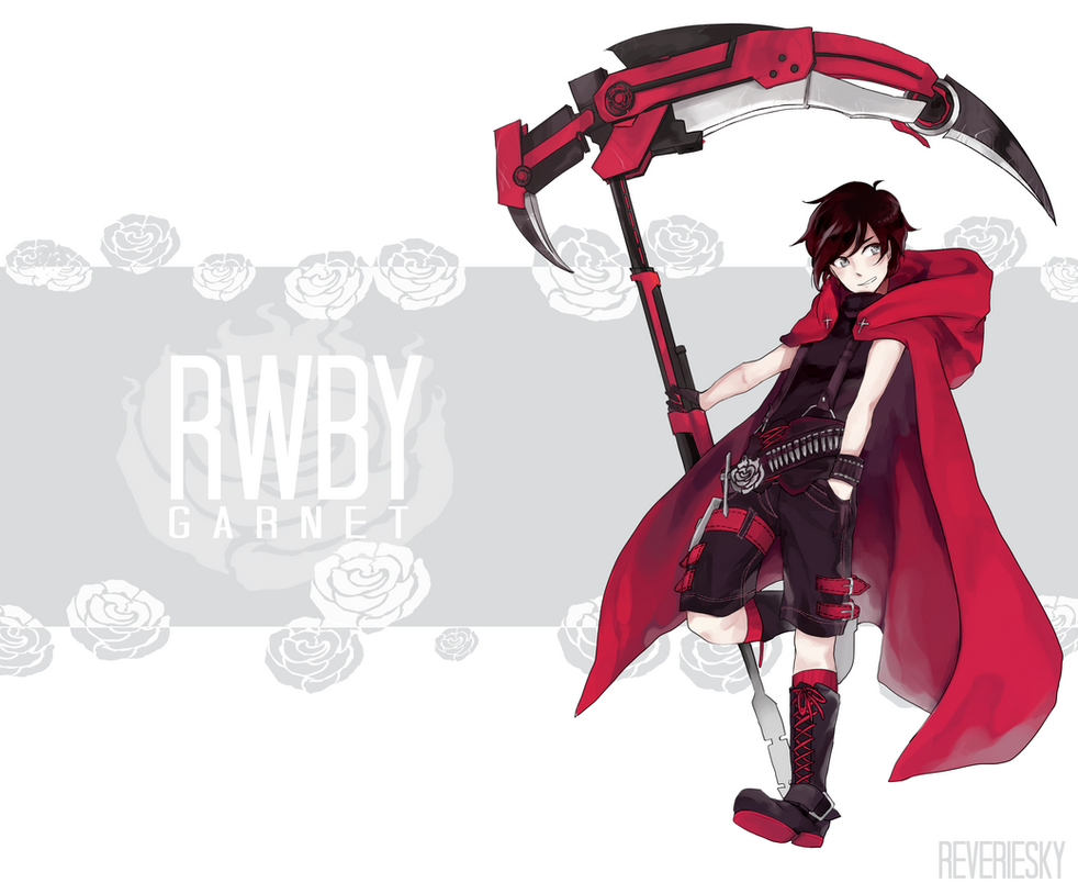
Image links to creator’s DA page
Okay, you can’t give a character that weapon, call him Garnet (I must use literally a ton of this stuff a year), and expect me not to bite.
Luckily, it still ranked on the favorable end of “easy” to “You have to be cosplaying for as long as I’ve been building robots to do it right”. I even made up a “make versus buy” chart for it:

One of the end goals of all the “Makes” was to use some of the rapid prototyping tools I had in the IDC which could be reasonably accessible to anyone – the Replicator 3D printer (which has sort of become our “student beater” machine), and a laser cutter. Harking back to my Maker Resources 2013 presentation at Dragon*Con, this year our group of maker-oriented con-goers (not to be confused with conga’ers) decided to host a panel with much the same topics, geared specifically towards costuming:

Unfortunately, I don’t actually have many pictures of my build, largely because it took place during the last two days before the convention where I was mostly aiding the completion of other props and handling 2.00gokart. But stuff did pan out. For instance, here’s a rose sigil thing that I made from the scrap outline of Cynthia’s rose cutouts. The bracket on the back was designed to snap-fit into the buckle of a large tool belt I bought and chopped up for this purpose.


The material is “silver” PLA, which I bought from Amazon (and which Zenn Toolworks hasn’t stopped calling me about to review… yeah guys, it’s filament! It’s all melty and stuff! Yay!)
It’s not silver in the traditional sense, but more like a gray PLA with some metallic sheen in it, which I suppose gets the job done.
A ton of other parts were also made in this same PLA – the large ammo boxes, for instance, which I drew up to hold two side by side .50 BMG rounds up to 6 high, because I don’t know if that was the idea or not, but had the dimensions of the .50 BMG in front of me. Plus, the scythe is allegedly also a .50 caliber sniper rifle. The ammo boxes had removable lids and actually served very practical purposes during the con. Besides those, the decorative crosses were also made in the same material.

I also used it to print the decorative bullets for the belts. Unfortunately, due to time, I didn’t make anything else to hold them to the belts, so we went without them – that will come later. I had a few feet of black cargo webbing and decorative rivets ready for the task.

Termed by my compatriots as “nerd-cute” or “nerdorable”
I think I shot pretty close in the end, eh? This was on Sunday, after Cynthia had broken her scythe demoing it so many times, so she designed and made a comically small stand-in from leftover MDF.
I ended up not being able to attend the panel, unfortunately, since Friday night / Saturday morning I was plowed over pretty hard by a (what I assume was) exhaustion-driven opportunistic flu/cold. It was bad – as in, I could barely stand up and walk straight bad. I ended up sleeping most of Saturday off in the IDC, and felt better enough on Sunday to tag along to the convention, since I paid $60 for that entry pass, dammit.
Which I lost, by the way, some time in the chaos of the week and had to borrow Nancy’s. Also, I never thought I would ever buy suspenders for any reason in life, but this was it. (They’re black, so not really visible in the picture).
While I have no plans for Dragon*Con but to bring back this character in more detail, Cynthia plans on a full rebuild of the scythe, so I’d pay attention to her site in the mean time.
2.00gokart: Year of the Weird Angular-Framed Karts
It’s back!
This year’s 2.00gokart session saw record application and enrollment. I had 64 students, mostly mechanical engineering sophomores but there were some serious left-fielders like Architecture/Visual Arts (course 4) seniors apply, but could only take 20. Man, my acceptance rate is getting to be almost as bad as MIT itself.
I expanded the field to 20 students (i.e. 10 vehicles) this year because of the experience over the summer with dealing with 27. It’s incrementally not much worse, especially now that I’ve produced more reference and lecture material which has cut down greatly on the time-consuming basic questions. The operations are now much more streamlined now that I have experience myself.
The rule changes this year are very slight, but are again designed to put a little bit of a twist in:
- Your vehicle now has to fit through a standard U.S. doorway, basically 33″ wide. Sorry Nelson. And like half of everyone from last year…
- You now have the option of getting once nice wheel…. or two Harbor Freight pink wheels. Cue evil laughter here.
Besides that and some minor clarifications, it’s the same thing as last year.

As usual, the class started with a “demo night” where everyone got to see examples from last year, and past students dropped by to visit. Here’s dgonz giving a short informative talk about the dangers of “dgonzing” in your chassis design.

A few weeks in, and people have their first orders.

This year, I got sheets of hardboard (Masonite) from a local wood distributor for super cheap, so everyone got to prototype their heads off on the laser cutter again…

…before I committed it to metal.
There are a lot more teams daring to wander outside the safety of 90 degree angles this year, including Triforce-kart up there. Which I’m sure is not the actual name, but I’m naming it just like I’ve named other things “5-degree-kart” (for having a frame that is a 95 degree trapezoid) and “bus-ass kart” which… you’ll see later.

The hardware in general is more robust this year, I think in part due to the added lecture / reference content and the availability of more examples from past years. Remember – these don’t come from kits, each piece is cut or machined from the students’ own designs.

In general, the design diversity is up from last year, which is what I want to see. Here’s one of the three teams that have elected to do live-axle, but they’ve also went and bought a differential (and named it Humphrey…). All this equipment came from Surplus Center.
Electrical system-wise, Kelly + SK3 still rules, but there are more dual-motor drive setups as well as one team going super experimental and taking a shot at using the Trackstar 200 – the big one. I eagerly await the results of this test since I’m using one on Chibi-Mikuvan.
Speaking of which…
Chibi-Mikuvan
Ah, now the section that will take the longest since it’s about me!
In the past few weeks, I’ve completely welded and assembled (and painted!) the frame, plus gained much more experience using the Shopbot CNC router to make the foam cores for the body. I also tried making the battery pack housings, but there’s either some quirk of the machine I’m missing or my parts are all scaled around 95% in the Y direction. The frame is almost mechanically done, upon which I’ll focus on getting the electrical system installed.

In the last episode, I cut all the tubing parts to size but had not yet put anything together. I had one giant weekend of welding some time ago in which I assembled the entire frame. The first things to come together were the steering knuckles, which also mount the brakes.

After dialing in my practice again with those, I decided to work on the motor mount. Recall that I’m using an angle grinder gearbox to “preduce” the motor speed before it goes into a chain drive. What better way to mount an angle grinder gearbox than with the disc guard ring it comes with? I cut the ring off using the other large angle grinder, then wire brushed the paint off in the critical areas.

Here’s the motor mount welded up, along with some of the outer frame parts. I wanted to put together as much independently as I could before joining the long frame rails, just so there was less fixturing shenanigans.

In the welding room…
I made tack welds to the frame with a TIG welder, but then came back with the MIG welder to finish the beads. This strikes many people as weird – and it kind of is, since typically you do it the other way around. My rationale is, the TIG allows me to exert no force at all to make the tack, whereas the MIG will always have a little wire poking your part and could therefore move the fixturing.
Well why not fixture better? I think the reason I fixture tenuously – generally with only those red magnets – is the same reason why I can’t finish the weld with the TIG welder. Time and patience. I’m insufficiently patient to do a nice TIG joint, when patience is the key virtue in getting a good one.
Spray and pray!

You know what they say, though. A grinder and paint…

…makes up for a welder who ain’t.
To be fair, there’s no shitty welding on the frame, but I also don’t take myself seriously enough as a welder to say anything more insightful.
The frame was thoroughly cleaned with acetone first, then I put down a few coats of self-etching primer followed by black engine enamel paint.

Overall, after a day of drying, it came out very nicely.

I test fitted some hardware to gain more insight on the lengths of spacer needed for the front wheels. Now that they’re mounted, the front disc brakes look even more ridiculous. Seriously, I think I could stop 3 other sketchily-braked entries in the next PRS race.

Rear axle in bearing blocks installed.

A closeup of the front axle kingpin and spindle assembly.

It’s up on four wheels! No steering parts yet….

The steering column supports are a fairly classic tactic around here of drilling some holes in Delrin (acetal) blocks. Acetal is a bearing plastic, so it’s super slippery while being pretty rigid. Two pin-jointed blocks constraint a steering column at any angle you please, then two shaft collars (one on the bottom, one up top) constrain it axially.
The driving link at the bottom is welded onto the column – instead of bolting into a face-drilled shaft collar like on Chibikart. This is just for expediency.
This forms the extent of the mechanical work as of yesterday. Likely right after I hit “post” here, I’ll go hook up the steering linkage and use a vise grip as a steering wheel and get pushed around the hallways.
Here’s some Shopbot work making the battery pack sides and the bodywork!

The battery pack sides capture the Fusion Sticks into groups of 5 so I can parallel the cells. They’re 3D milled parts by design; I guess I could split them into 2D layers, but I wanted to learn the 3 axis milling mode of the Shopbot. The material of choice is a 2×10 chunk of sanded fir I bought from Home Depot. To stay within the PRS budget, I need to make this from something reasonably strong but cheap, and wood actually qualifies well there.

After roughing and finishing, the end result looks pretty good!

I made two versions. The one on top is both roughed and finished, and is the best quality. The bottom one was one of my attempts to shortcut the process by only roughing. The Partworks software that came with the Shopbot is sort of limited in the things it can do – it’s for beginners and general non-engineers, after all, so isn’t full featured like MasterCAM or HSMWorks. It won’t cut the part out in “roughing” mode, only finishing, so I tried to trick it into thinking the part was thicker than it actually is such that it would “cut out” in the roughing cycle by virtue of stopping too far down. This did work, but the internal features were then too far down also!
Seems like the only way to really make this work is to make sure the stock is thinner than you tell it, which couldn’t work in this case because the parts are 1.5″ thick and so is a “2 unit” dimensional lumber.
I’ll just put up with the extra 30 minutes of finishing. What’s weirder is that these parts are seemingly compressed in the Y direction by about .05 inches consistently, almost like someone put in a “scale 95%” in the program that I haven’t found. I’m going to try running another version sideways (long direction oriented in Y) to see if it is signficantly shorter, which would tell me “someone set a fixed scale percentage”, or still 0.05-0.1″ shorter, which would indicate to me an offset problem.

With some lessons learned making the battery sides, I started routing out the foam cores which will eventually be between the fiberglassy bread in the composite sandwich shell.
I bonded the foam together with slow-curing epoxy that was filled with “milled fiber” until it was pasty. Which is really overkill since it seems like 77 spray adhesive worked just as well, but let’s keep it legit since this thing is totally going into space after all. I made several bricks that were to contain the four sides of the body.
Foam is messy. You can’t use the dust collecting nozzle because it would hit the part, so the foam flies everywhere and generally covers everything. And it’s ultra static-y when you try to vacuum it up.

Doing a finishing pass after the initial rouging!
Foam machines like a dense air, so I set the machine to run as fast as it could. All of these parts finished in around 1.5 hours.

One of the sides right after cleanup.
The foam was held to the MDF disposable surface by…. hot glue. That’s it. I drooled hot glue in a vaguely grid pattern, about 2 lines per foot, in roughly the shape of the part, then slammed the foam brick down before it cooled off. It worked great!
To dislodge the part, I used a giant dustpan to split the hot glue under the edges, then slowly pulled up with it.

IT’S ALMOST A THING
Too bad that I welded the front wheels 1 inch too far forward – mistaking the end positioning of a dimension while jigging it up.
This means two things: One, that the frame needs to be cut in 2 places, and 1 inch subtracted from one side and added to the other, or two, the body has to get split and a 1″ foam extension added.

I went for the second, since it would also make the gluing easier to manage (I didn’t have any 48″+ clamps). So I split the body in half on my hot wire cutter. A 1″ cross section will be made and bonded to the body, bridging the two halves, and the whole thing rejoined with carbon fiber rods running lengthwise to give the bridge some structure.
Bonding the rear panel to the two sides was easy, since it was nice and arch shaped. I just piled heavy things on top to keep everything down, and used 1 clamp in spreader mode to set the angular displacement (It wanted to lean to one side). For added legitimacy, I used the fiber-filled epoxy here, as Burt Rutan would.

The front half was also easy, just another mess of clamps.
I received an order of 2 gallons of Nice Epoxy yesterday, and otherwise have all the supplies needed to do the fiber layup on-hand. I’m hoping to get to it this weekend, but it miiiiiiight involve a little more psyching myself out beforehand.
For now, I’ll work on getting the frame to mechanical completion because then I can wave it in my own students’ faces to encourage them to finish!


