12 O’Clocker: The Completion, and Überclocker Upgrades for This Year; Dragon*Con panel information

What a week! 12 o’clocker was completed early on, then I began to focus more intensely on upgrading and repairing Überclocker for this year’s competition. 12 o’clocker is currently working and undergoing test driving. It handles enough like Überclocker, but I hope to be able to second-nature the peculiarities of its operation. Plus, it’s fast. Just how fast? Find out now.

Continuing the manufacturing of the “solid state reactive outriggers”, I needed to drill some 1/4-20 clearance holes through the Rockwell C44 hardness spring steel. The week before, I purchased two solid carbide drills off eBay for a cool $7 each – if you have the patience, eBay is a wonderful industrial and machinery supply house – to do this one task. These are straight-flute bits designed specifically for drilling shallow holes into very hard metal. The straight flute maximizes stiffness, but of course does not allow for very deep holes.

Carbide wins over steel any day, and this process was totally straightfoward. The curls that came off this thing could cut you open in an instant – to prevent this from happening in MITERS, I hammered them all apart and trashed them before anyone could discover them on the mill.

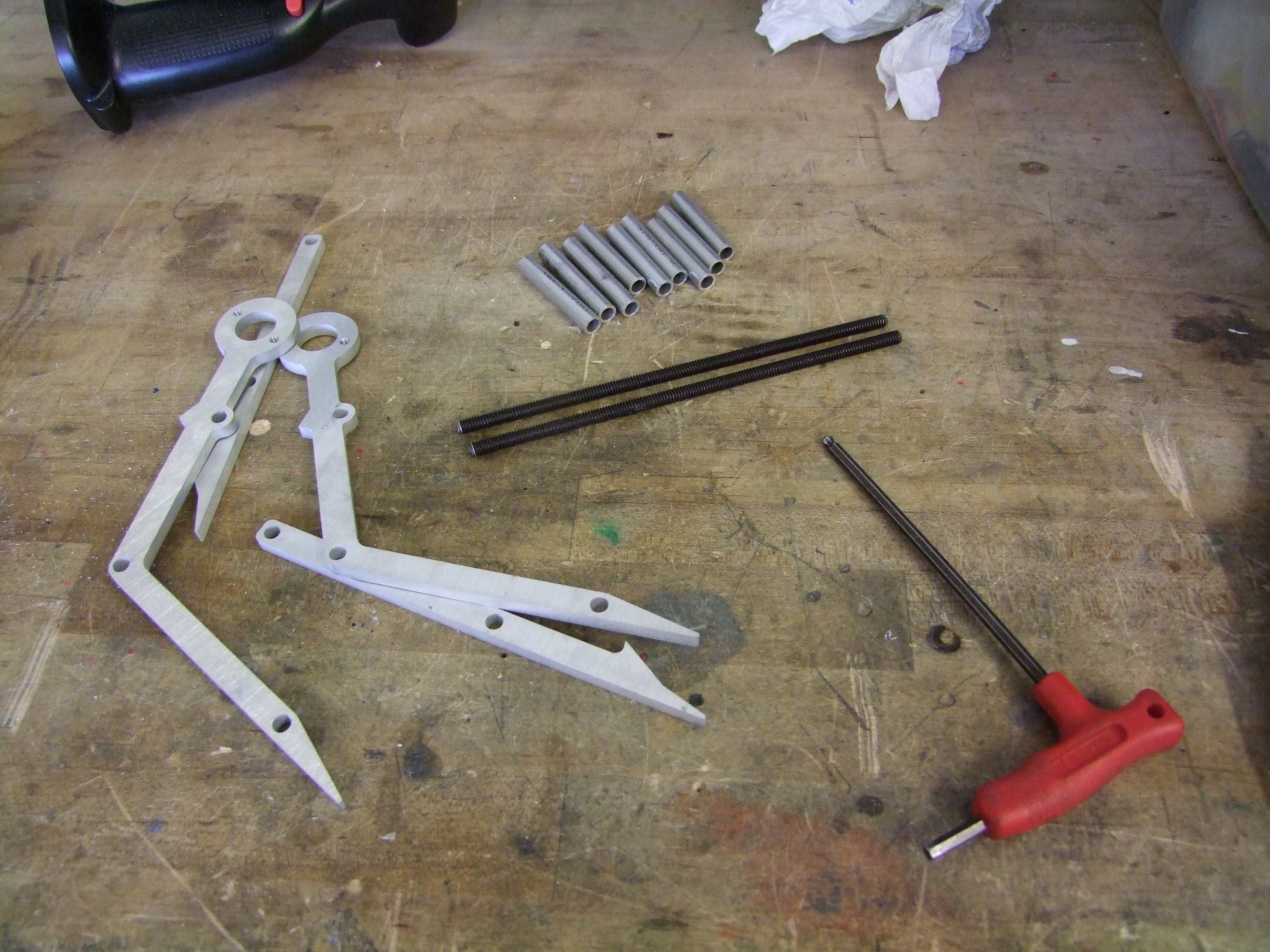
Here is an assembled leg. The aluminum end blocks are also drilled clearance, and a bolt holds each end block together. I elected to take this route over threading the aluminum because the bolt could impart much higher fastening forces without stripping the thread.

The legs mounted. I unfortunately didn’t have any lower profile nuts, so the big locknuts on the end kind of function as 2nd-order fish-hooks. Strange how a normal 1/4-20 nut – just about the most common possible nut – couldn’t be located this time of day. I bought an entire bag of 1/4-20 Keps and grade 8 plain nuts from McMaster in retaliation.

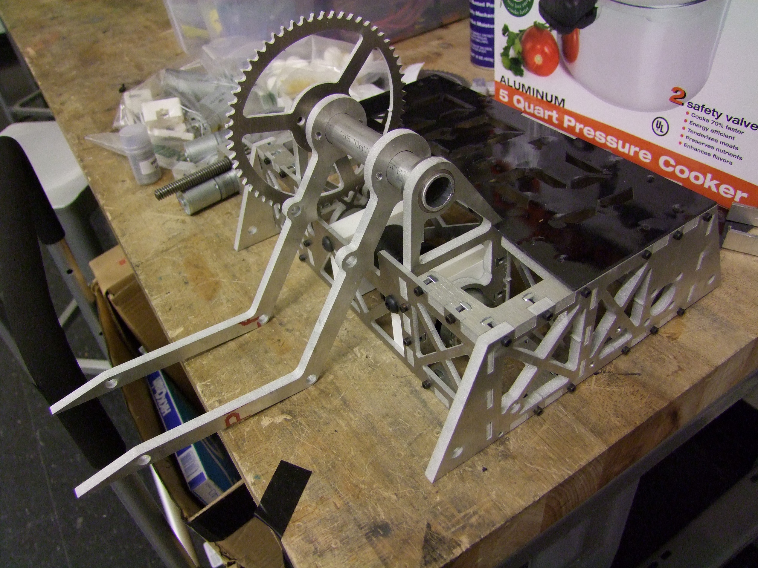
With the bot now mechanically done, I turned immediately to electrical work. Remember the original CAD picture and how it had the cells in the middle and the RageBridges above the motors? I found that arrangement wasn’t optimal. Instead, some arranging of parts in real life found a better arrangement which kept the battery mass in the rear. This arrangement did however force me to mount the Ragebridges vertically. That, and the batteries shouldn’t be lying directly on top of the drive motors because that would be unfavorable to the motors in high impact applications… like combat. I needed to come up with a vertical rack for the controllers, and some kind of shelf for the batteries.

I went back to the 3D model to generate these required components. This is the result, after a few minutes of staring. The black vertical guides hold a hardboard (HDF, pegboard) plate upon which the RageBridges are bolted. Two auxiliary motor supports keep the battery from jouncing on the motors directly; these were originally slated to be made from Delrin, but I only had enough of the material left to do this right exactly once….and didn’t. So they ended up being made of HDF anyway.

The little squiggle at the bottom is a flexure joint to keep these plates tightly stuffed onto the motor. Unfortunately, they were made pretty much useless in HDF.

I decided to make the battery first, since it could take a first balance-charge overnight while the Ragebridge mounting end guides were 3D printed on my Up? machine. The first step is to select a group of “relatively” matching cells out of the cell medley. I generally reserve the highest voltage, most closely matched ones for EV use. This is because robot packs may be frequently swapped out and charged externally (with the implication that you’re usually using an R/C style balance charger), but an EV pack needs to be buried inside the vehicle and out-of-balance or weak cells can degenerate from lack of charge monitoring very quickly. It actually took a little while to gather enough middle-of-the-road cells. The majority of the A123 Collection hovers at 3.29 volts these days, and I was looking for cells in the 3.20 to 3.25 range. The camp is pretty well split 90%-5%-5% between good ones, shady ones, and ones that are totally dead (defined as an OCV of under 2 volts).

The end-to-end architecture of the pack meant I had to fold over the interconnecting battery braid once I was done with a joint, and I had to do these one “string” of 3 cells at a time. Usually, in a professional setting, packs like these are made by end-to-end soldering using a “hammer head” iron tip, or with spot welded tabs which are then similarly folded over.

A side effect of folded tabs is that they are well exposed on one side to attach the cell taps for balancing to.

Many of my robot and rideable things have featured custom A123 packs. If you’re interested the basics of assembling a custom pack, here’s a short writeup getting the basics of the process by a former duckling student of mine. With some… uhh, more detail and rigor, this is essentially what I train people regularly to do these days – after all, if we’re going to have a pile of donated batteries, it is better to train people to safely and correctly use them than to try and hide everything. In my opinion. If you’re a safety bureaucrat, you may disagree.

Balance taps added. These days, I usually don’t bugger with soldering and crimping my own JST terminals, but buy balance harnesses off eBay en-masse and cut them up. These are professionally crimped and molded, and usually only cost a few dollars.

While the battery pack balanced, I uploaded the print job to the Up printer and by the next morning it had produced the RageBridge rack in question. The HDF parts were laser cut.

RageBridges pulled “from stock” and mounted to the rack. I’ll totally have some of these at Robot Battles.

In the process of wiring it all up. Notice that I’ve bussed the wiring together on the RageBridges – this is one shortcoming of the current style design which I openly acknowledge. Recall that these things were designed originally to replace two Victor 883s in Überclocker. It had 2 sets of power wires already, so it stayed like that in the “production” versions.

The battery is just coated with 2 layers of heavy polyolefin heat shrink, and then unceremoniously stuffed in place. There’s just not enough room to pack all the wires in – a bit of stuffing has to be done. Unfortunately at this point I decided to scrap the glowing 12:00 idea because I didn’t have any space left in this thing to add an EL inverter.

The last few bits of distribution wiring added. Notice the small yellow and brown wire on the right side. This is a direct battery tap for whenever I decide that I have the capability of adding gaudy lighting.  The master power switch for this bot is just “disconnect the battery” – as such, the battery wires are just run outside the bot. When on, the wires are stuffed into the protective confines of the front right frame rails. The RageBridges are set to 25 amps (drive) and 20 amps (weapon motors), which is a pretty egregious waste of their capacity. I’m strongly contemplating a RageBridge “mini” version that retains the Hysterical Current Limiting scheme but can be more finely tuned for amperage at the low end – say 25 amps continuous and 50 for short terms.

With the wires complete, it was time to function-test and pack everything up! I had to play “change the motor wires” a few times to get 12 o’clocker’s control directions to match up with Überclocker

Here’s the ‘press shot’, so to speak, of the completed bot. The weight is 12.05 pounds.

Yes, it’s over, but I’ll remove one of the standoffs from the clamp arm if it’s really that bad. Or just wear the wheels down a little. Worst cast, I’ll replace the steel drive sprockets with aluminum ones.

Remember that part where I said it’s fast? It’s like, unnecessarily fast. Here’s how fast it is:

The calculated ideal top speed with these new motors is somewhere north of 20mph (30 ft/s). In the narrow hallway I wasn’t confident enough of its straightlining ability to push the throttle to full. In the narrow arena confines, it will never be able to hit this top speed, but the acceleration (also shown in the video) is blazingly fast. I think 12 o’clocker is going to warrant a slightly different strategy against opponents than Überclocker just due to it speed. The extra speed overhead will give me some room to maneuver around and behind people instead of strategically avoiding head-on engagement like with Überclocker.

I found out in sparring matches with Turboencabulator that I needed some more current on the lifter and drive, so the adjust-o-knobs were turned up to 30 amps (drive) and 25 amps (lift). Those extra few amps made for substantial improvements in the lift.

Here’s the D’aaaaaaaaaaawwwwwwwwwwwww size comparison shot with 30lber Überclocker. 12 O’clocker is currently ready for action. Speaking of which…

Überclocker

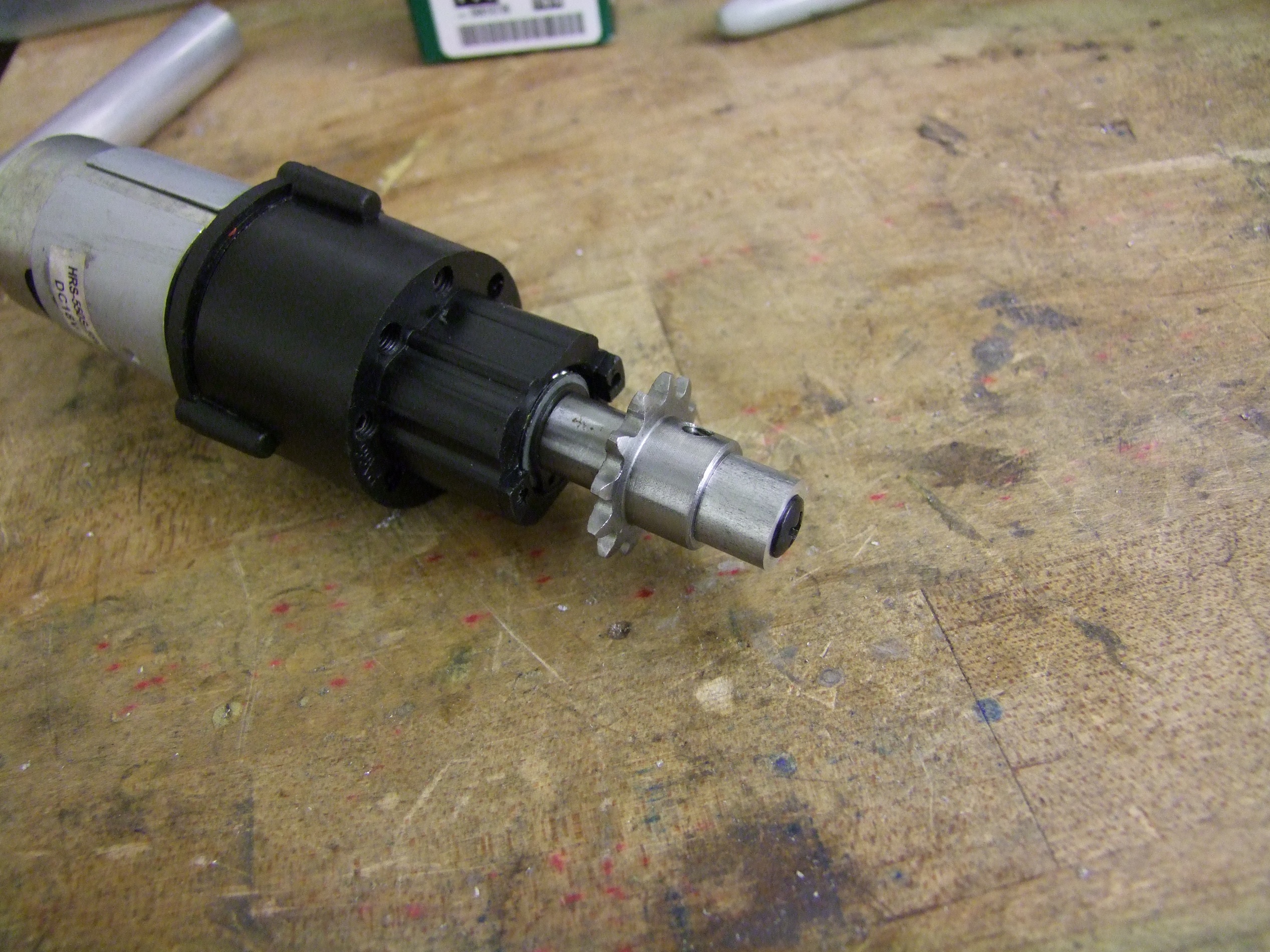
The big change I wanted to make to Überclocker this year is making a more robust clamp actuator. As recapped before, the issue with the Cold Arbor harvested actuator is that it was slowly destroying itself from being made of untensionable chain drives, and the lead screw was damaged pretty badly at Motorama. The shallow pitch leadscrew also made it prone to “bolting” itself, tightening to the point where it couldn’t loosen again. The reason I purchased the IGxx gearmotors was to see if they can act as a commercial replacement for my custom hacked drill gearboxes. That post concluded that yes, they could, but not in a way I would like, so I made the hybrid all-metal gearbox from two of the ones I purchased.

The gearbox was later wrapped into an actuator design:

The architecture of this is very similar to my other custom actuators. The gearset is from Vex (I’m obliged to say every time I mention Vex: When the hell did they get so legit?). In the center of the top gear is shoved a machined down McMaster fast-travel ACME leadscrew nut. The two bronze bushings supporting it are flanged to also handle the thrust loading, and not shown in the model is the gigantic loogie of grease that this whole thing will be basked in.

The lifter model refined a little and inserted into the robot model. This actuator orientation better uses the leadscrew length (instead of having like half of it as filler length just to reach the clamp arm. One thing that I don’t like about it now is that it does not actually shield the motor that much better. With a standard-can speed-400 (RS-385) type motor, it’s okay. But, I only had “long can” motors (RS-395 type) that won’t grenade at the 26v electrical system, and those stick out a little further. The standoff is there as some degree of protection and as a lower travel limit for the leadscrew.

It’s totally fine against blunt-sided bots, but a good high speed wedge drive can probably reach the motor and bend it. I almost want to re-engineer this whole system from scratch instead of just patching parts onto existing structures.

This is what the reach looks like. If I *am* facing a blunt sided opponent, then this actuator is also a nice “hard stop” for the back of the fork. It doesn’t really stick out that far.

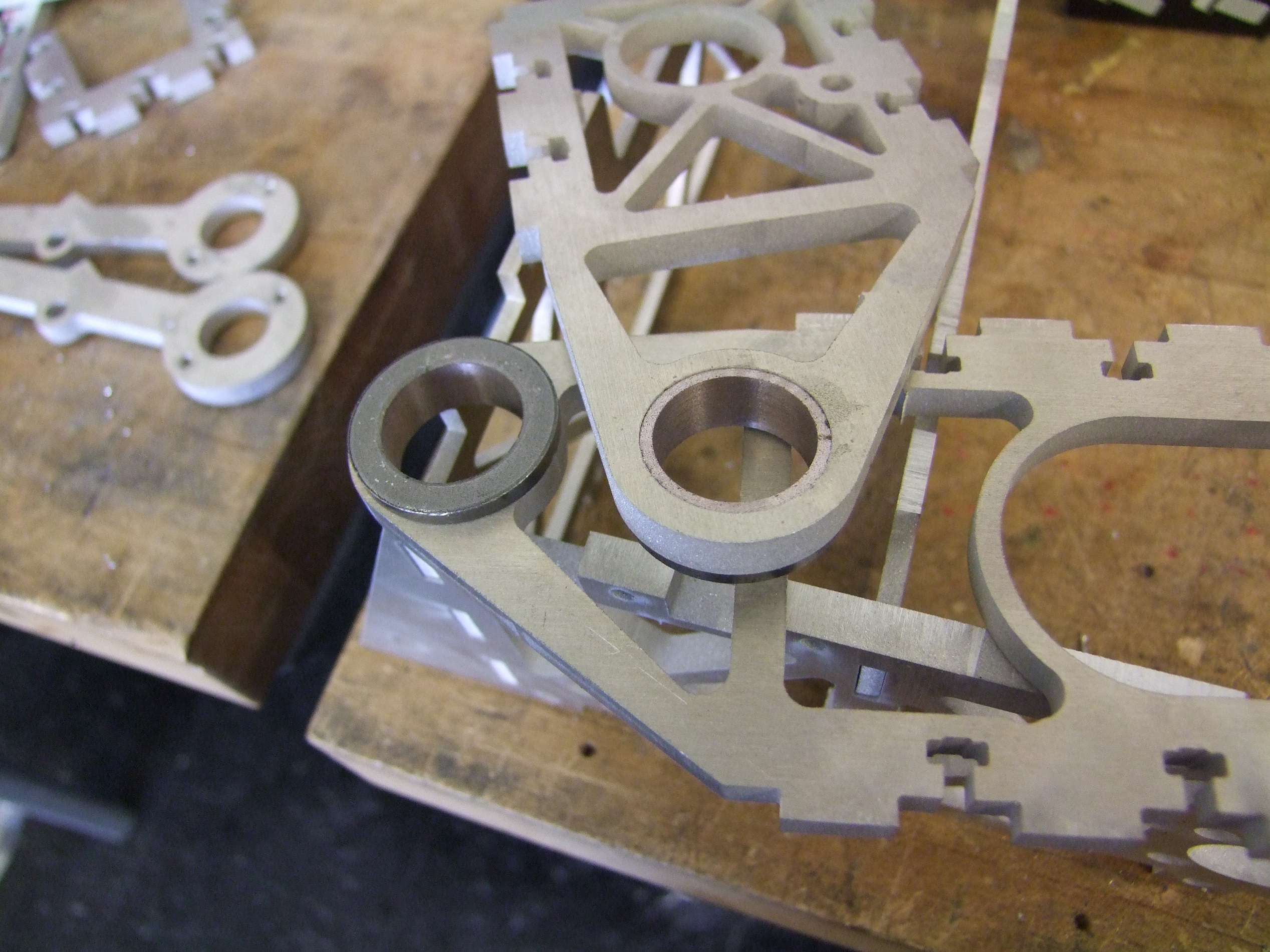
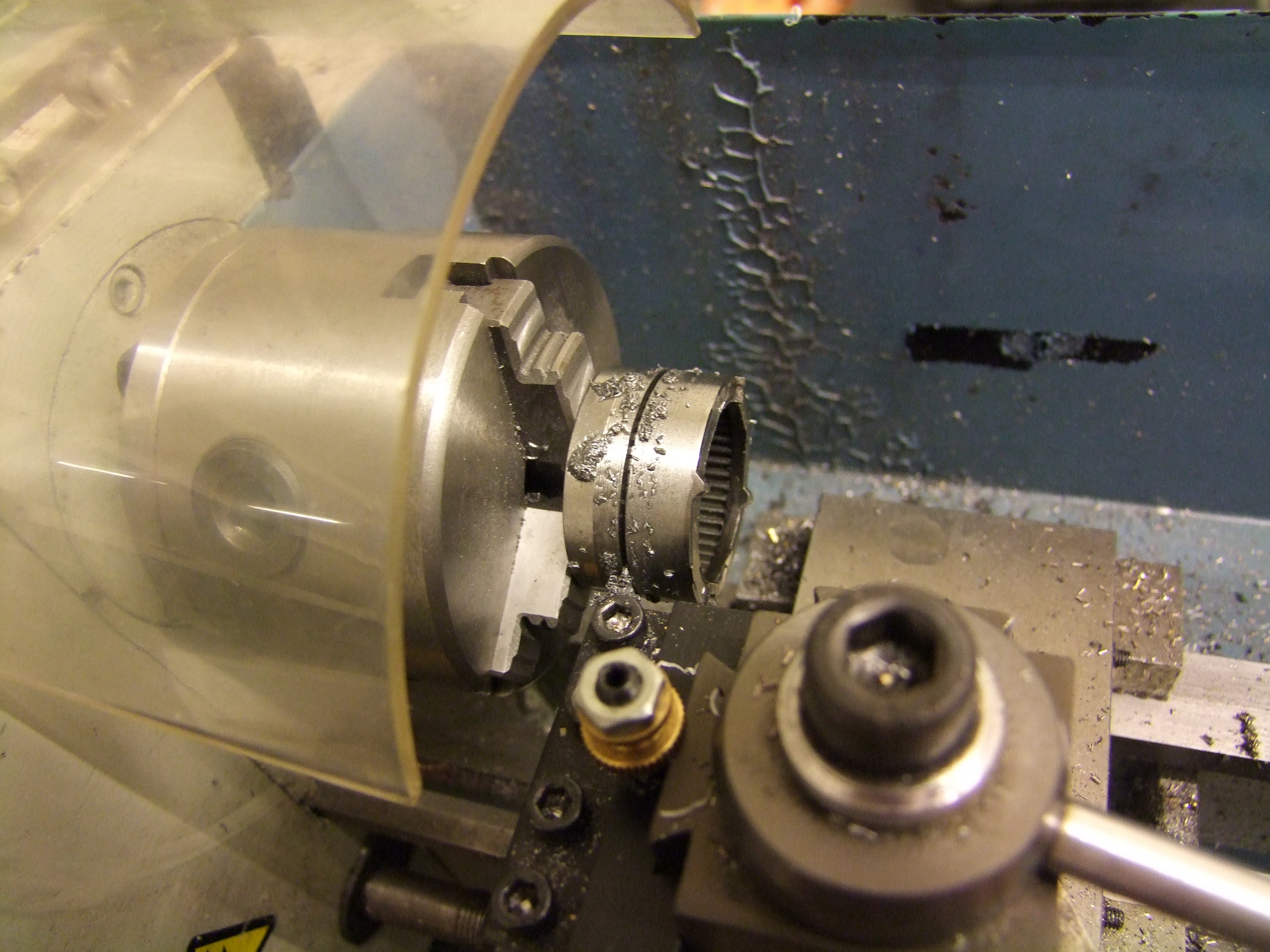
It was time to start cutting metal. Here’s the ACME nut about to lose about 50% of its volume! The threads had to be machined off and the part turned to press-fit diameter, then cut off at 1/2″ long. I was wasting 2/3rds of it by mass, but until McMaster makes raw Acme nut stock…

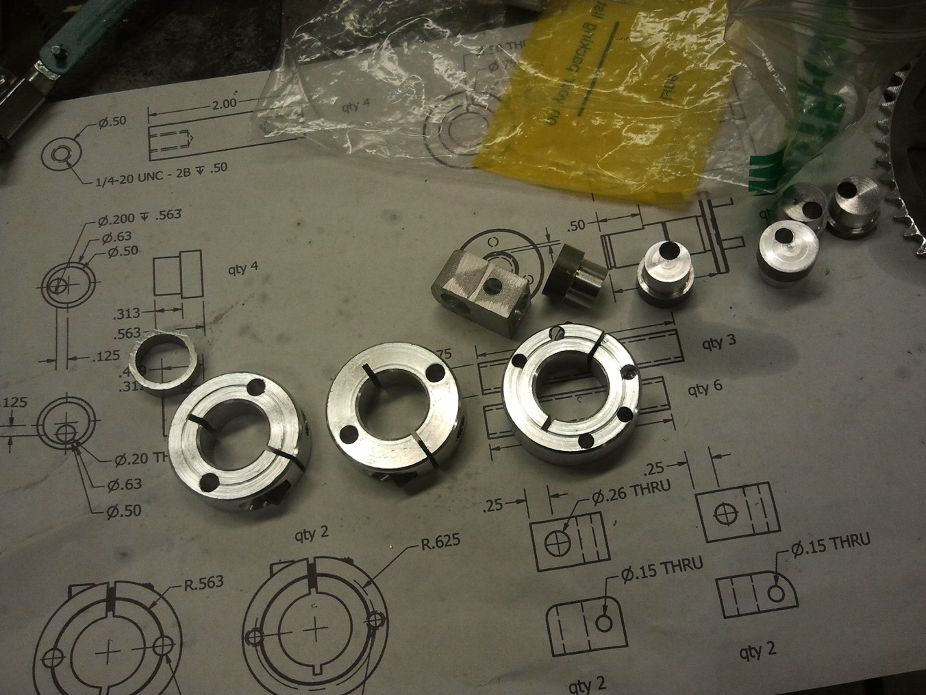
The nut turned down and the gear bored out. They are to be combined using copious amounts of green Loctite and an arbor press.

Pictured behind it is one of my “troll drawings” – in which I put about 10 parts on one page with just enough dimensions to remind myself of what I’m doing. Some times it even fails at that.

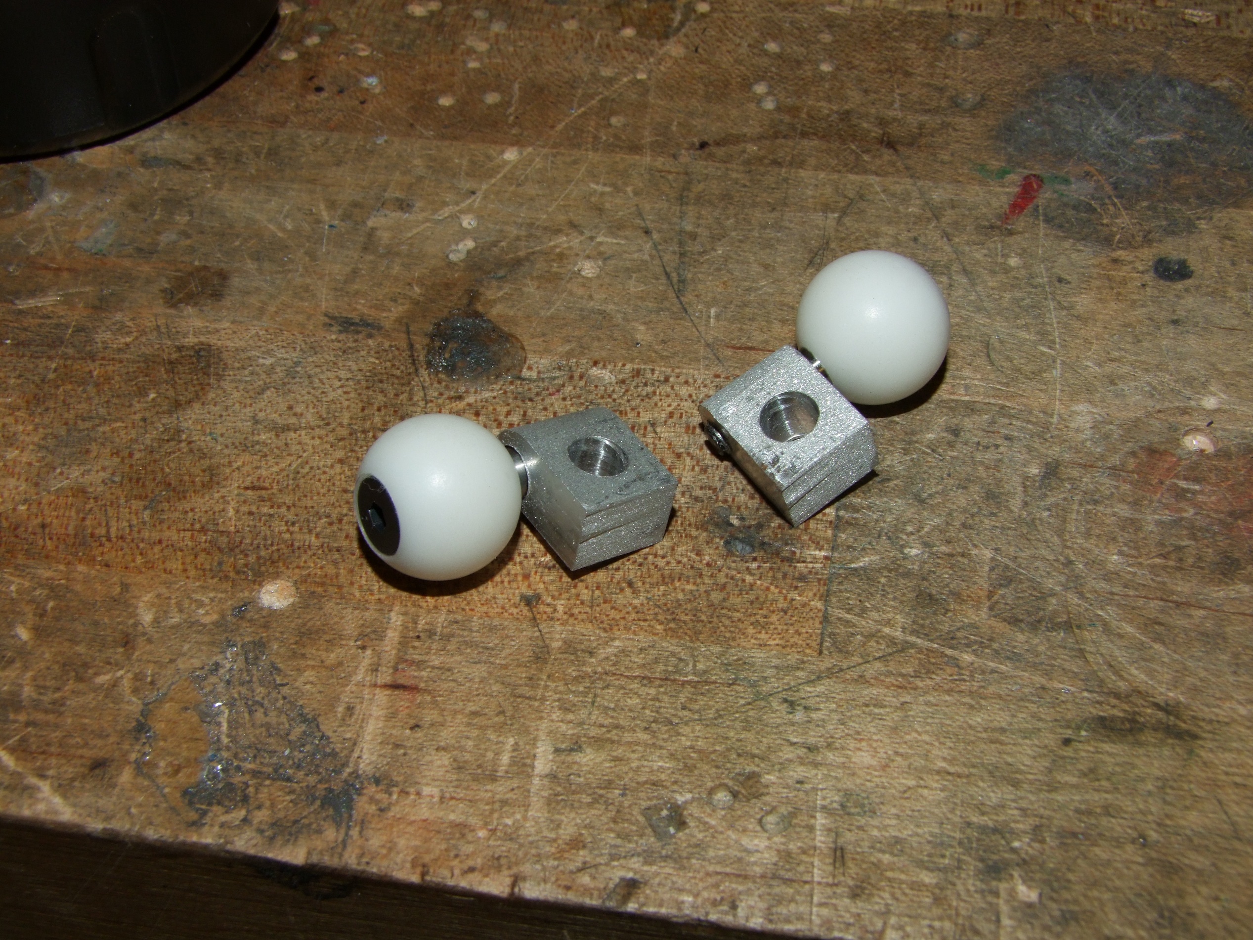
The lower gear is attached to the motor by… well, not much. I machined a hex adapter from some steel hexagonal stock. It’s set screwed to the motor, and the gear simply sits on the hex. That’s it – that’s FIRST Robotics engineering for you. It just has to last the season.

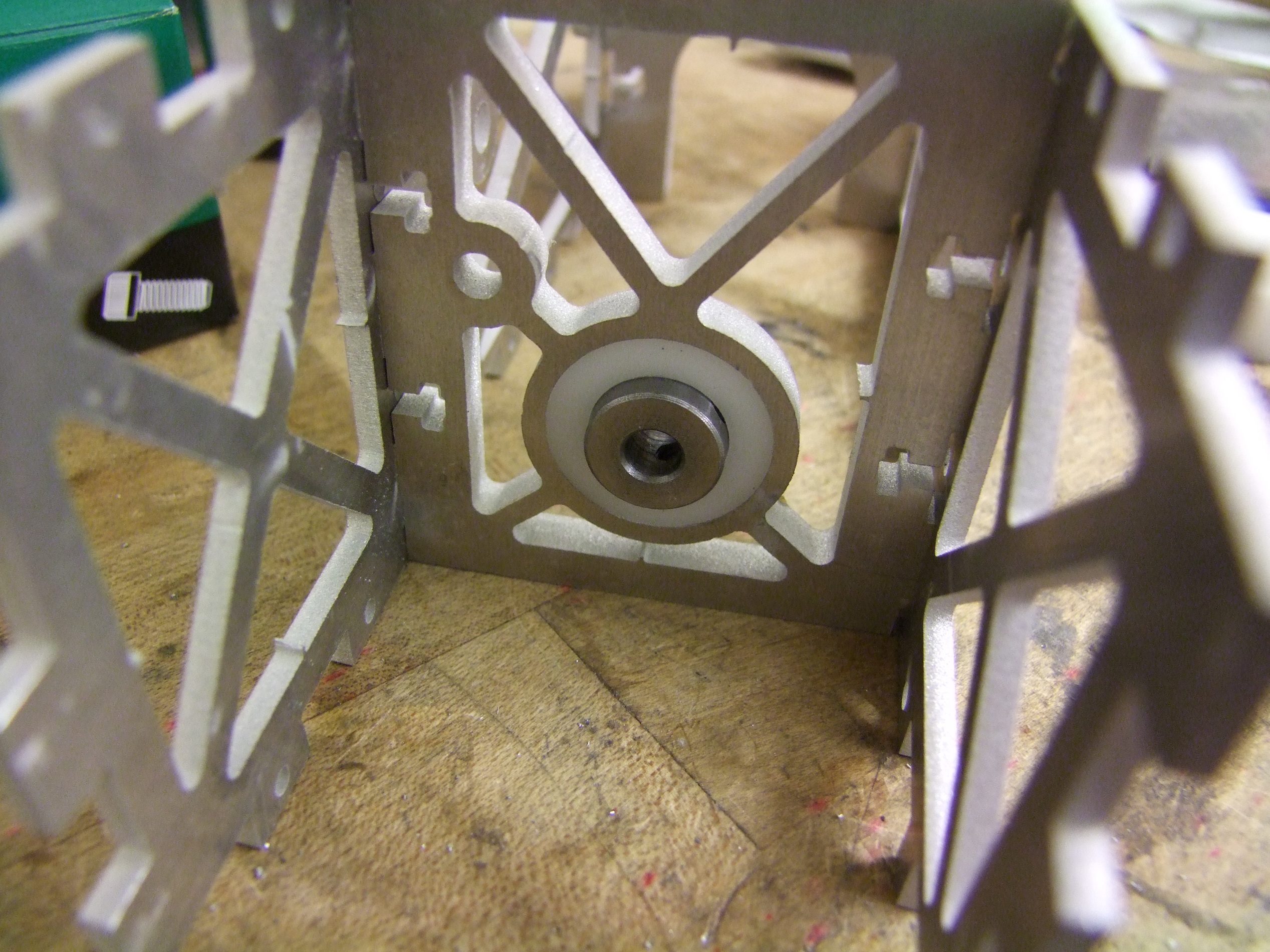
What everything looks like when put together. On the bottom (motor side), the hex adapter is supported by another one of those R1212 bearings.

The new leadscrew cut to length and with attachment flat machined.

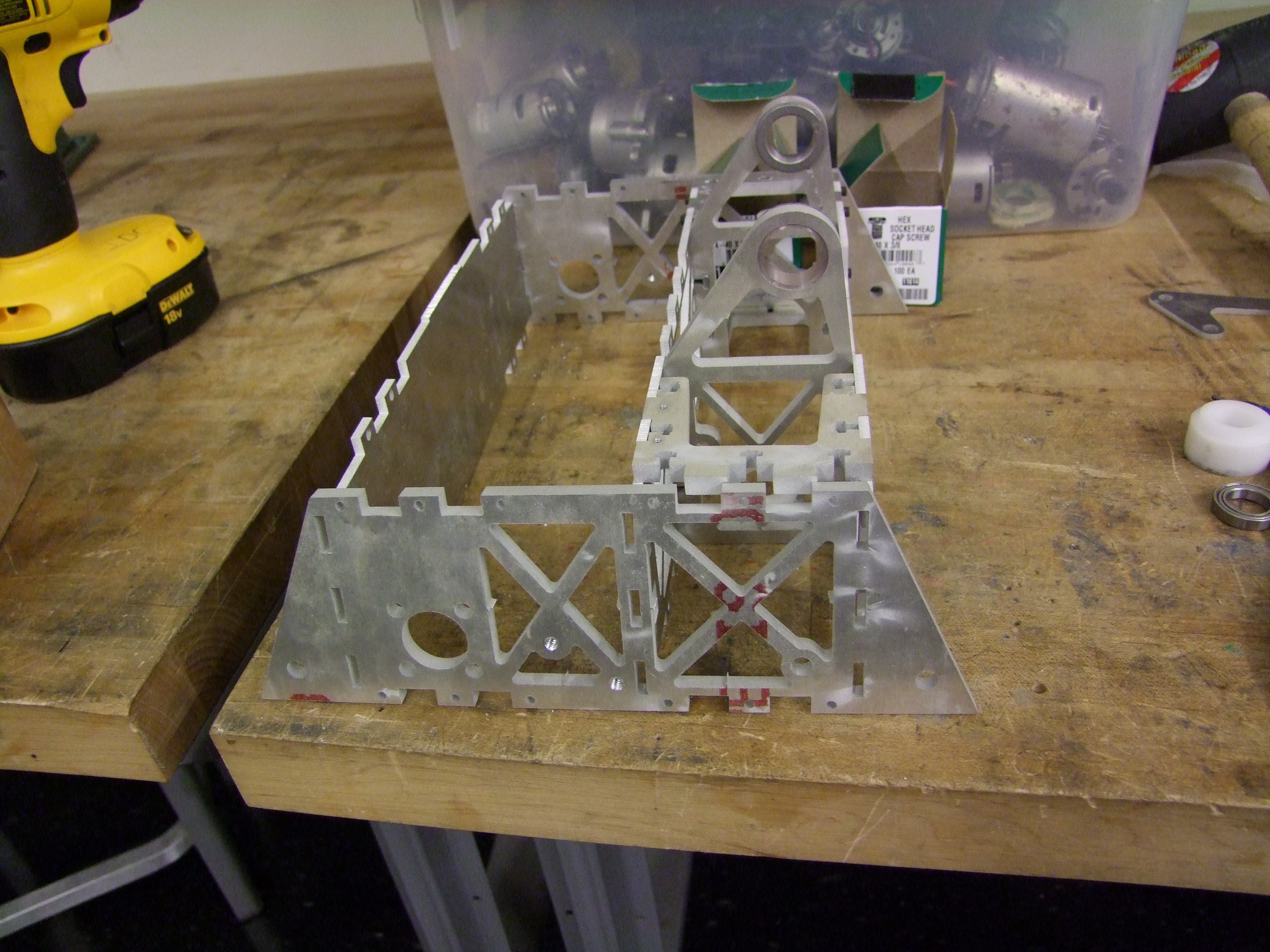
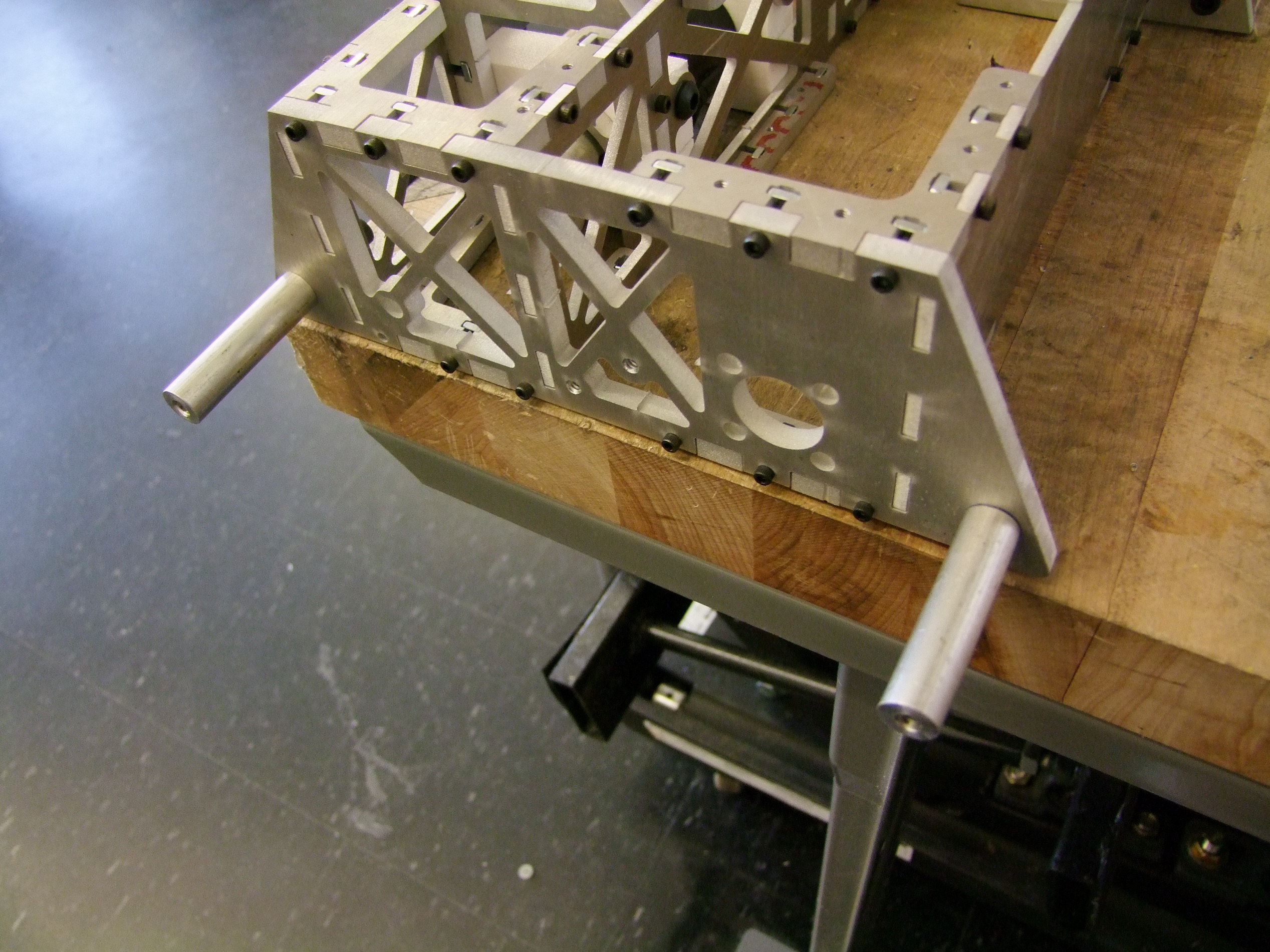
And finally, everything mounted in the bot. See how far that motor sticks out?

When the clamp is down (in a position ready to close on something), it isn’t a problem since the motor is well shielded by the aluminum body of the actuator. I guess one thing that I have to watch out for now is someone taking a high speed run at me when the clamp is all the way up.

I extended the umbilical cord from the bot to account for the new actuator placement, backing up the wire the entire way with heat shrink.

Fully installed, wired up, and with a healthy dose of lithium grease. I ran some tests where I practice “clampbot yoga” using Null Hypothesis as a chew toy:

This new actuator is great so far. With the actuator motor’s Ragebridge half set to 15 amps, I can literally run it from endstop to endstop, full speed, and still release in either direction. The RB’s fast current limit algorithm helps here, as does the high lead angle of the screw so it can never “bolt” itself together. The clamp speed has also increased to about twice what it was before. Clocker should miss less grabs now because of this upgrade.

I sparred Clocker briefly with Null Hypothesis (feat. Jamison as the pilot of Null) just to shake everything up from Motorama and to try and catch problems early:

Guess this wasn’t really that representative of a match – the floor is super slick polished concrete, first of all, instead of hard outdoor carpet. However, I did confirm my vulnerability to someone getting stuck between the springy legs and the fork. Careful maneuvering will be needed to make sure this does not happen.

I put the bot away for a few days to work on 12 o’clocker, but with that affair now complete, it was time for some pre-competition preventative maintenance.

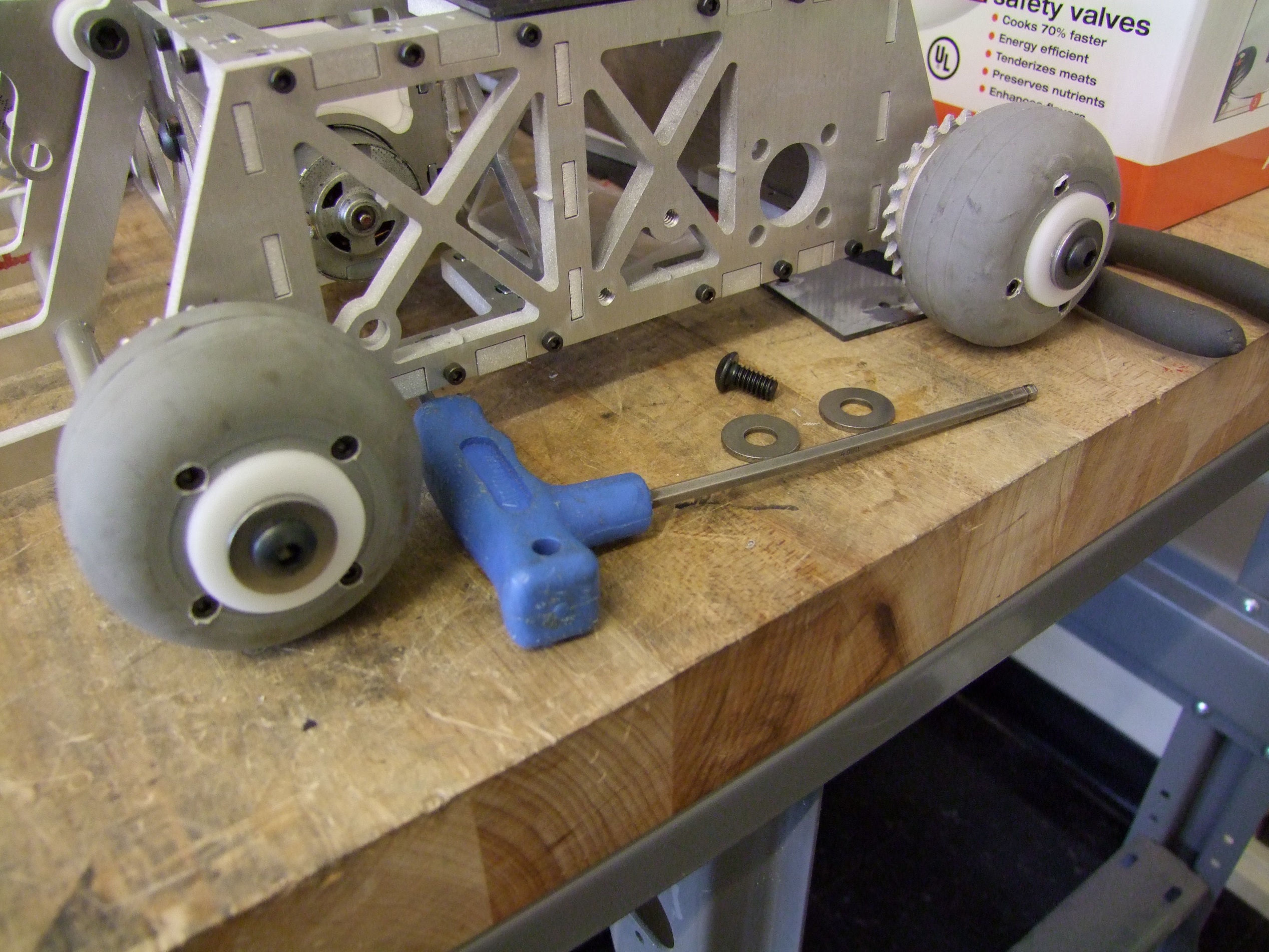
I tore down both drive halves of the bot completely to check for issues. Are the DeWalts still in one piece? Is anything really, really worn down?

I mean, besides those wheels. They’re pretty destroyed, and only got more destroyed after Motorama from demos and sparring. I did make spare wheel stock before Motorama, so I decided to give Clocker 4 new wheels and keep the half-worn front tires as spares for now. (Due to the way the fork can load against the ground, Clocker goes through back wheels much faster than fronts.)

All I needed to do to swap wheels was to use one of the spacer rings holding the sprocket away from the wheel as a template to drill clearance holes into the new ones.

Überclocker is now cleaned and buttoned back up.

At this point, both of the bots are totally ready to fight tomorrow if need be. However, the story doesn’t quite end there. In these past few days, I also went and upgraded certain parts of my 3200lb 2WD wedgebot to prepare it for the 1000-mile (one way…) trip to Atlanta and ideally back. That’s a story for later on.

Dragon Con 2013 Panel Info

I’m coming back as a speaker this year on two panels for the Makers & Robotics track at Dragon Con. See the full schedule here!

The first one, CAD and Maker Resources, is an extension of my talk last year on where to buy things for your mechanical whirlygigs and doobobs. Except this time, I’m focusing more on how to make nice things. By this, I mean exploring using free and free-ish CAD programs to better design out your projects before laying into a piece of aluminum with a plastic safety scissor, and taking advantage of modern rapid prototyping and digital fabrication resources. Basically, How to Build your Everything Really Really Fast for Kids who Can’t Build Good.

It’s been my observation that many folks, especially those already well-versed in the EE and software side of things, are dying to get into mechanical projects, so it will focus on such possible routes to start immediately instead of mocking things up with plywood and hot glue. Having been on all 3 sides of the proverbial coin (the knurled edge is a side, I swear),I’ll explain why hardware, and especially mechanical, projects are more involved in general and how they differ from the typical fancy PCB.

The second is in conjunction with my partner in hoodrat shit, Adam, and will concentrate on Electric Vehicles. The panel last year was a primarily discussion and Q&A driven session where we used peoples’ questions about EVs to dive off, and that will remain the same this year. Hopefully some hardware will be in attendance too.

I’ll at least try to have a set of slides made for both of these; no guarantees, of course, that they are actually representative of the panel. If the media resources are available, I will record the sessions and upload them after the fact.

12 O’Clocker Epic Post

Damn. This past week -and-a-little has seen 12 O’Clocker basically go from a plate of aluminum to an essentially complete bot minus wiring. I’m making good time for Dragon*Con 2013 after all, it seems. In a slight departure from my usual day-by-day- updates, I’m going to make one single epic post capturing the construction up until yesterday or so. I tended to stay later than usual in the shop in the past days, and writing up daily posts would have pushed my already marginally stable bedtime out to a level which would have made interacting with anyone else… difficult.

As I mentioned previously, by the time I made the introductory post, I had already frozen the design and put most of the parts down on aluminum. The first stages of assembly were doing finishing machining on these parts, as well as machining that which I could not figure out how to waterjet. These days, my ‘style’ is reducing everything to a waterjettable or McMasterable condition and trying to minimize manual machining operations. After mechanical assembly was complete, I spent time figuring out where exactly the electrical components – batteries and RageBridges – will be mounted internally, and this is the stage of the bot right now. Here’s forty pictures (from #24 to #64!) for your amusement. I recommend packing drinking water and high-carb food supplies.

This is the final series of parts made for this bot – previous parts, seen in the upper regions of the picture, were rolled in with a waterjet-cutting session for the SUTD summer go-kart class (which I still owe a full writeup on, before I completely forget it!). In most respects, 12 O’Clocker is a pretty simple bot, and there were (relatively) few parts to be cut.

One thing which mystifies most people who see me waterjet is that I manually path everything. I started this habit some time in 2010 when I was getting tired of losing entire plates to the shoddy Autorouter built into OMAX Layout. When I manual-path, I instruct the machine to make one part at a time (holes and all), then move onto the next whole part, and I try to route in a fashion which does not cross over anything it cut before. Because the path includes only whole parts, the plate can accidentally shift (such as in the all-too-common nozzle collision with a pre-cut piece) and I may only lose that one part. The autorouter likes to do all the holes and internal features first for some reason, so if anything messes up, you usually lose the entire sheet. It took only one $200 write-off to permanently scare me into manual pathing. Additionally, I use the Tab function like a maniac, on anything that looks like it can stick up and bump the machine, and on all plastic parts.

This way, I can route an two-hour-plus long job, then practically go to sleep and then come back to find everything all good. Okay, so I don’t really go to sleep, since the machine still needs abrasive feeding.

So here’s everything! The obligatory picture of the pile of parts includes all the aforementioned waterjet-cut puzzle pieces, a few different motors, and Delrin balls.

I machined the black Garolite, my choice of robot covering, on low-pressure to avoid substantial delamination. I further suspended the Garolite on a piece of waterjet brick, which offers a much higher support density. Without these two addenda to the process, I’ve always had massive delamination from Garolite. In this plate, the delam is limited to areas around the holes and initial pierces.

I design the holes in these parts to be already on-size for finish tapping without having to redrill (usually). The first step in assembling a puzzlebot is to tap with threads that which needs to be threaded. Because all of the holes are necessarily thru-holes, it’s easy to chuck up a gun tap (spiral point tap) into a drill and then just go at it. I mixed up a little cup of machining coolant (high-lubricity oil-water suspension – a.k.a the juice that flows in every CNC porno) that I dunked the tap in after every part.

In the background is one of my collections of random cordless tool motors. I think there’s like 50 drills (most of which are parted totally down) and like 10 cordless saws in there.

Next up was machining down the main lift shaft bushings. My approach to live weapon axles is to make them huge, and usually this implies buying metal tube stock to use as shafting. Now, the difference between metal you buy as shaft and metal you buy as tube is that the former is implied to be precision-finished to a size under the nominal (i.e. a 3/4″ shaft might be .748″) so it for sure will fit through your bearings and other driven parts. Tubing has no such guarantee, and in fact is usually oversize. The cheap 3/4″ 6061 surplus tubing I purchased was a cool 5 thousandths oversize.

To compensate, I bore out the bronze bushings on a lathe beforehand – the dimension needed, plus a thousandth or so for the bearing squish fit into the housing. These days, Tinylathe is my tool of choice if only because it’s like 5 feet away.

There was one problem I ran into right away. I didn’t have the right bearing to support the lift motor shaft. I ordered it, but it most definitely didn’t come on time, and I was sort of itching to put this together instead of waiting for the parts. That, and I couldn’t find the 13-tooth sprocket I originally specified. Since 12 O’Clocker isn’t going into space or (ideally) poking around inside an organ, I decided to make a design change on the fly to adapt to the parts I had on hand.

The bearing was going to be a 6803 type, 17mm bore bearing to basically envelope the hub of the sprocket. The 13 tooth sprocket’s hub was just the right diameter to shave down a little and throw into a 17mm bearing.

I had on hand 12 tooth sprockets left over from the EV class, and a 6802 type bearing (15mm bore). I decided to machine an adapter to turn the 26mm 6803 housing into a 24mm 6802 housing, and machine down the smaller sprocket hub to 15mm. This increases the reduction of the lift arm just a hair, which is  differentially speaking to my benefit, since it would both slow down the lift another few % as well as reduce the required current to lift an opponent.

….but in the end, I just shoved a machined Delrin donut in it and called it a day. Didn’t even machine the sprocket.

This is a very slow-moving part already, and drill gearboxen already have bearings! The whole purpose of this bearing is just to reduce the bending load (versus shear load) on the shaft. It doesn’t need to be sophisticated, and can just be Delrin, the venerable bearing-grade plastic I had a few rods of. After spending all of 3 minutes on this, I moved on with my life.

Assembling the puzzlebot now.  The part precedence I designed in means I fasten together the center towers, then the U-braces on the ends, then finally shove the sides on. If you’re thinking of designing a puzzlebot, and don’t read anything else in this whole post, read this: all of these parts were cut on an artificially close nozzle offset so all external dimensions are about .005″ smaller, and all internal dimensions .005″ larger. This is a cheat code to account for the waterjet’s taper between entry and exit sides, something inevitable unless you are really rich-ass and have a taper-free or 5-axis cutting head.

If you don’t have the ability to run a custom offset, then you must design all the slots larger and tabs smaller in CAD. Or, you’re going to be miserable filing and grinding everything.

These parts required very light belt sanding to take off the burrs and tabs, and only in a few cases a hit to the thickness of the tabs.

I’m sort of round-robin machining parts here – in one round, me versus everything. I put the puzzlebot aside and tested the fit of the Angerboxes. Beforehand, I threw these gearcase models on a Dimension 1200ES machine to be made from ABS plastic.

It turns out that the drill gearbox CAD model I had used a smaller diameter ring gear by about 0.5mm than the ones I picked out from the Tomb of Tool Parts. These drills are usually similar enough to swap parts into each other, but different enough that any design involving them is going to jump your precision-havin’ ass in an alleyway. I had to machine down the ring gears a little to fit them.

After a radial pass, I sliced off just enough to contain one stage. These ring gears are made via sintering, so it turns to powder when machined. This is actually the sign of a shitty sintering job, but hey, $20 cordless drills.

6801 type (12mm) bearings support the 12mm drill spindles.

No, I’m not using those plastic gears – they were just the first things I grabbed from the Tomb of Tool Parts to test thickness fit.

After verifying that everything fit as designed, I put these gearboxes down and went to…

…the lifter gearbox. This is a totally stock 18v-native, 36:1 drill gearbox that I replaced the first stage gears with spare steel ones. The 12 tooth sprocket seen in previous pictures was bored out and threaded for its 3/8″-24 spindle. The long standoff piece at the end spaces out the reverse-thread M5 flat-head screw which typically locks a drill chuck in place.

Another blob of 3D printer poop with a drill gearbox shaped cutout will hold this motor in place. I basically made this mount to let me emulate the motor mount style used on Überclocker, which uses DeWut motors with side mounting holes. The generic drills don’t, so the sandwiching mount does.

Overly-long 1/4″-20 cap screws fixture the motor to its mounting cradle. In soft plastics (or at least, anything where $fastener_hardness >> $material_hardness), you generally want 3+ fastener diameters to take advantage of the material strength.

As a random aside, the recommendation for situations of comparable material strength (say aluminum threads with steel bolts) is one screw diameter, and materials of nearly equal strength just 4-5 threads. This is why steel nuts are usually made really skinny – count the threads on the inside of a typical machine nut some time.

The first pretend-o-bot! At this point, I was getting pretty damn excited to see this thing finished.

After the pretend-o-bot assembly, I moved on to the last item of the day, which was to put together the top clamp arm. This was a quick standoff assembly job.

I attached the end-effector, the rubber bumper, with a convenient chunk of 1/8″-wall aluminum square tube I snagged before getting to that part of the design.

The next window of progress was spent making some of the repetitive side parts. Seen here is my “sheet of every part drawing since they’re so damned simple anyway”. The majority of these are standoffs of various kinds.

The inter-fork spacers are designed to be made using some 3/8″ OD, .050 wall 6061 tubing. This was way better than the other option, which was to drill out all of those from a solid rod.

Pictured above are all the fork standoffs and two of the Angerbox output shafts in progress.

Axle pins attached. This is my first intentional foray into single-support wheels in a long time. Single-support wheels tend to last … not very long in combat, so I made everything here overkill. First, half-inch diameter axles on anything that weighs 12 pounds.

The 1/4″-20 bolts are unnecessarily long, to give the aluminum a stronger core, and the threads are actually embedded under a half inch of clearance hole as to preload most of the structure where the most stresses from impact will be seen.

It’s often these little unseen details which can make or break a design, and I’m really hoping for make this time.

Time to assemble the fork! Like Überclocker’s fork everything I build now? , this is just a pile of plates and standoffs…

…that looks like this. If there’s one lesson I have to summarize 2.00Gokart and the SUTD summer EV class with, it’s tighten your damn bolts. Untightened and unloaded structures are just flappy metal noodles.

Moving on now to the drive hubs, these are simple Delrin one-piece jobs. Since Tinylathe is too cute to contain a 1.25″ Delrin rod all the way through, I had to cut off chunks and sacrifice about 1/2″ of length off each to grab them.

The final machining step for these hubs is to purposefully chatter an endmill through them. Why? It’s once again the difference between buying shaft and buying metal rods. The aluminum rods I had standing by are just plain-finished loose-tolerance rods! They’re actually much larger than their nominal 0.5″ (more like 0.505-ish), because you’re supposed to machine them to something smaller with more precision.

Well, I didn’t have a .505 drill bit, nor an over-size reamer. Nor a boring bar long enough. The shortcut is to take a super-rigid cutter and purposefully guarantee it no center, so it just has to deal with it. I basically revved the spindle to full speed and manually shoved the thing through the center bore.

It made a terrifying screeching racket, but the end result was a bore crudely enlarged to about .510″ (varies greatly…)

Fits great though. Here’s 12 O’Clocker looking like someone stole its rims. In reality, I haven’t bored and machined the wheels yet.

The wheel assemblies were, again, designed to smash together quickly and template itself for finish machining. It has four parts – the wheel, a 1/8″ thick ring spacer, the sprocket, and the Delrin hub.

Here is one wheel as a test fit, and the clamp arm assembled on for looks. At this point, I called it a day for assembly because I discovered I ran out of 2″ long #4 screws. I needed long bolts to go through the wheel and spacer and into the threaded holes in the sprocket, acting as lug nuts.

I moved onto making the rest of the irritating small parts. Here are five blanks for the eggy-rolley-cam tensioners machined out.

Because they differed only in length, I lined them up one next to the other on the MITERS Bridgeport and drilled the off-center holes in one shot.

While downstairs, I revisited an old friend, the MITERS South Bend 10L, upon which many of my freshman and sophomore shenanigans were first performed. For how hard it gets wailed on by students, most of whom aren’t experience machinists, it’s never had any problems. 1950s style brute force tends to come out on top. I used the machine’s much larger swing to chamfer the tips of the main lift sprocket.

The MITERS lathe to me represents roughly the most useful machine size for the general hobbyist. It’s a nominal 10″ swing machine, with a 42″ bed, and a big through-bore. Tinylathe is too damned small, and the other machines in this building are enormous – 16″ and 19″ swing. I think the 10″ class has just enough feedback to enable really precise work on small parts, but can still contain sizeable workpieces like wheels and round plates. Plus, my favorite lathe (I have one, just like I have a favorite weird 1980s Japanese cargo van) is the Monarch 10EE, nominally a 10″ machine. Round dial, please.

Here’s a collection of little side parts. The shaft collars are for transmission of lift torque to the main lift fork, and you might notice on of them took me a few… tries. I tried taking eyeball and by-feel shortcuts on the Bridgeport right away again, but remembered about as fast why I only do that for machines I use every day and know exactly the recent alignment history of: because not everyone trams the head and squares the vise. Whoops.

Well, time to bust out the edge finders.

Fast forward to Day…. three? four? Whatever like 2 days ago was. I had dug out my box of 1.5″ long #4-40 screws, but they’re still too short!

Or are they? I decided to get this damned thing together, buy 2″ bolts later, and just counter-bore the shorter screws into the wheel for now, so they could still reach the other side.

So here we go. All 4 wheels counterbored up and installed!

Next comes the lift axle itself. The shaft collars are loosely scrwed into to the forks, the lift shaft slid through, then the screws tightened. The white residue on the shaft is a healthy dose of Teflon anti-seize paste. The reason is that this time, it’s aluminum shaft collars and an aluminum sprocket rubbing on an aluminum shaft. Without this intermediate layer, I would soon have a very curiously shaped solid aluminum modern art sculpture as all of the above galled into eachother and became one. The antiseize lets the clutching action of the clamp shaft collar still occur.

I maneuvered the lift chain tensioner into place and secured it for the time being. It will be adjusted out slowly as the bot wears in the lift chain.

Chains typically stretch a few tenths of a % shortly after installation as soon as they are loaded, since the burrs and high spots from manufacturing get worn down quickly. In my case, with so many custom sprockets, the net amount is a little more because I also have components besides the chains to wear in.

Here is a more detailed view of the eggy-rolley-cam tensioners. The ball bearings will directly push the chain (no intermediate sprocket teeth here).

The bearings themselves are type R1212 bearings, which is part of a series that is basically the 68xx of the English unit world. I’ve spent a long time searching for thin-section inch bearings that don’t cost $9000 each, and for the 1/2″ case, at least I have found the R1212. Apparently the other sizes (3/4″, etc…) are nonstandard and its code depends on the manufacturer. In contrast, searching ‘R1212 bearing’ gives me a world of generics.

With the tensioners ready for installation, I went hardcore after finishing the Angerboxes. The motors I ended up using are some unknown 12V (ish?) 550-class motors I found in a bin. The reason is because I’ve actually ran out of matching shitty 18v drill motors! I have a mishmash of gearboxes with motors, but I couldn’t find two matching 18v motors, especially not with the 36:1 standard 9 tooth pinions. Oddly enough, I have more 24:1 drills than 36:1, and this gearbox depended on the (far more common) latter pinion. I harvested some pinions from the Tomb of Tool Parts and pressed them on these motors.

Now that I’m running 12v motors, I’m actually going to drop back from the planned 8S (25.6v) system to a more sane 6S (19.2v) system. 30-lb Clocker does run a 8S-equivalent system, but with “real” motors which are 18v native anyway. A 12v to 24v overvolt in this case would have given me an unacceptably high top speed and would probably bake the motors in short order.

Three harvested, mismatching metal gears ride on the output pins, and the whole thing is closed from the back from harvested mismatching wear washers. I’m like the Iron Chef of making stuff from shitty drill parts. I did say that all of these drills tend to be the same enough…

Here’s one Angerbox closed up with another one awaiting. The shafts have milled flats (not quite visible) to aid in using set screws properly.

The first installation of all drive parts on one side is complete! This spent a few minutes just running from a power supply to seat all the bearings and run in the chain. A portion of the back wall is now covered in a very weird vertical black splatter mark, like a highly precise mechanical crime scene. The same process was repeated for the other side.

Lift chain in place! Now I could manually wang (that’s a strict technical term) the fork up and down and backdrive the motor.

One issue is that switching to a 12 tooth from a 13 tooth sprocket meant my original tensioner design doesn’t tension very much any more. I’m almost at the limit of travel and the chain will most likely slack beyond that limit. The narrow confines of these 3 rolling elements should not cause deraining problems, though. Worst case, I’ll put a spacing ring around the outside of the tensioner so it can push further.

Clamp actuator now installed, and run back and forth a few times with a dose of lithium grease. This motor will definitely be unhappy on even 18 volts, but I’m hoping the current mode of the RageBridge can delay the onset of magic smoke arbitrary far into the future.

After all this was done, I turned the bot over to install the bottom plate.

I decided to get a start on the very last item on the list of manufacture for the mechanical side: The springy legs. I segmented the 3/32″ thick spring steel bar into two 8″ lengths with an abrasive cutoff wheel and selective belt sanding. These will have two holes each put into them with a solid carbide drill bit, then have the accessories attached.

Here, have some robot googly-eyes.

These are actually the front rollers for the legs above. The axles these things ride on are 1/4″ diameter hardened steel shoulder screws, counterbored all the way into the Delrin ball, and extending halfway through the aluminum. This is to make sure that bending impacts are borne as much as possible by the aluminum and not the weaker threaded area of the screw.

This is the mostly mechanically done pretend-o-bot , with the only thing missing at this point being the legs. I cut out a “window” using 1/16″ LDPE sheet to cover the 12:00 and give it some contrast. I hope to have this whole thing back-lit by a big EL panel.

That’s it for now. I’m going to now compile the previous day-ish, and whatever happens today and tomorrow, hopefully into one more post to complete the construction of the bot. That, and reveal the upgrades to 30lb-Überclocker for this year!