Überclocker Remix: Round Four

how is robbot formed

how robbot get moters

Questions for which I wish I knew the answers. One full week left of Überclocker work, half of which is Orientation for the Class of 2013, which means I sort of have half a week left.

The past while has been filled with high-intensity gearbox manufacturing. I am now relieved of work obligations, so that means I can plug on the build day and night. The drive motors are done, and with another run on a waterjet, I can have the drive base structurally complete. Hopefully that will occur by the end of the weekend.

Oh, yeah, pics. Usually by the end of a build, I’ve somehow wrecked yet another camera, but fortunately my surrogate machine is too big and chunky to forget about, then drop something on. The past few posts on this site have been garnished with pictures courtesy of my Fuji S9100, which I got for the excellent price of Free a while back.

It has too many buttons for me to operate properly.

I made two more embryonic drive gearbox halves while the Bitch Chuck was still dialed in. The bearings were put in as a test fit, but then I figured that they were sealed and it was okay to proceed without removing them.  They are 6901 type 12mm bore bearings. Each pair of two will carry a modified drill gearbox shaft in the gearboxes.

All that remained to do after putting the radially symmetric features in was… put more radially symmetric features in. Here are the gearbox halves completed and ready for population with planetary gearing. The counterbored holes on the front half are for 6-32 socket head screws to bind the halves together.

Okay, it was time to start parting out the old bot. I needed the all the juicy parts out f Uberclocker 1 – motors, gearboxen, and the Victor controllers.

Oh, and the drive wheels. I had neglected to order more 2.5″ Colson wheels. The ones on the bot were in pretty good condition, so I just transferred hubs.

Überclocker got more banged up than I remembered. When I pulled the left drive motor out, a few chunks of plastic fan fell out the vent holes. Closer inspection revealed that the motor had actually thrown a rotor winding. I wonder how long the bot was running like that, or why the motor even ran at all?

The other motor also lost its internal fan, but was otherwise functional.

I elected to not reuse these. Wheels can generally be missing chunks and still work fine. Motors gnerally do not.

Okay, so what to do now? Speed 700-size motors are more difficult to come by. I started scanning the surplus channels for possible candidates.

I installed one of the drive wheels for kicks. The mount holes still need to be countersunk, so ultimately I’d have to remove it again, but hey.

The robot will have about 0.5″ ground clearance when all is said and done.

I continued down on the drive gearboxes even without a motor to attach to them, running on the confidence that mass production has made virtually all Mabuchi 775 size (Speed 700) motors share a common bolt pattern.

Aha, a candidate motor arrives!

These HTI units are commonly found in the surplus channel. They appear to have been manufactured en-nutty-masse for some kind of small vacuum cleaner. Regardless, AllElectronics has them for $3.75, MECI for $3, and the Robot Marketplace for $Jim, are you fucking serious?

Downside: They’re not neutrally timed. The timing appears to be 5 to 7 degrees in the CCW direction. This means Überclocker will be tracing a hell of a big circle all the time, but, as the laws of mathematics dictates, under small arena-sized deviations, a curve can be considered straight.

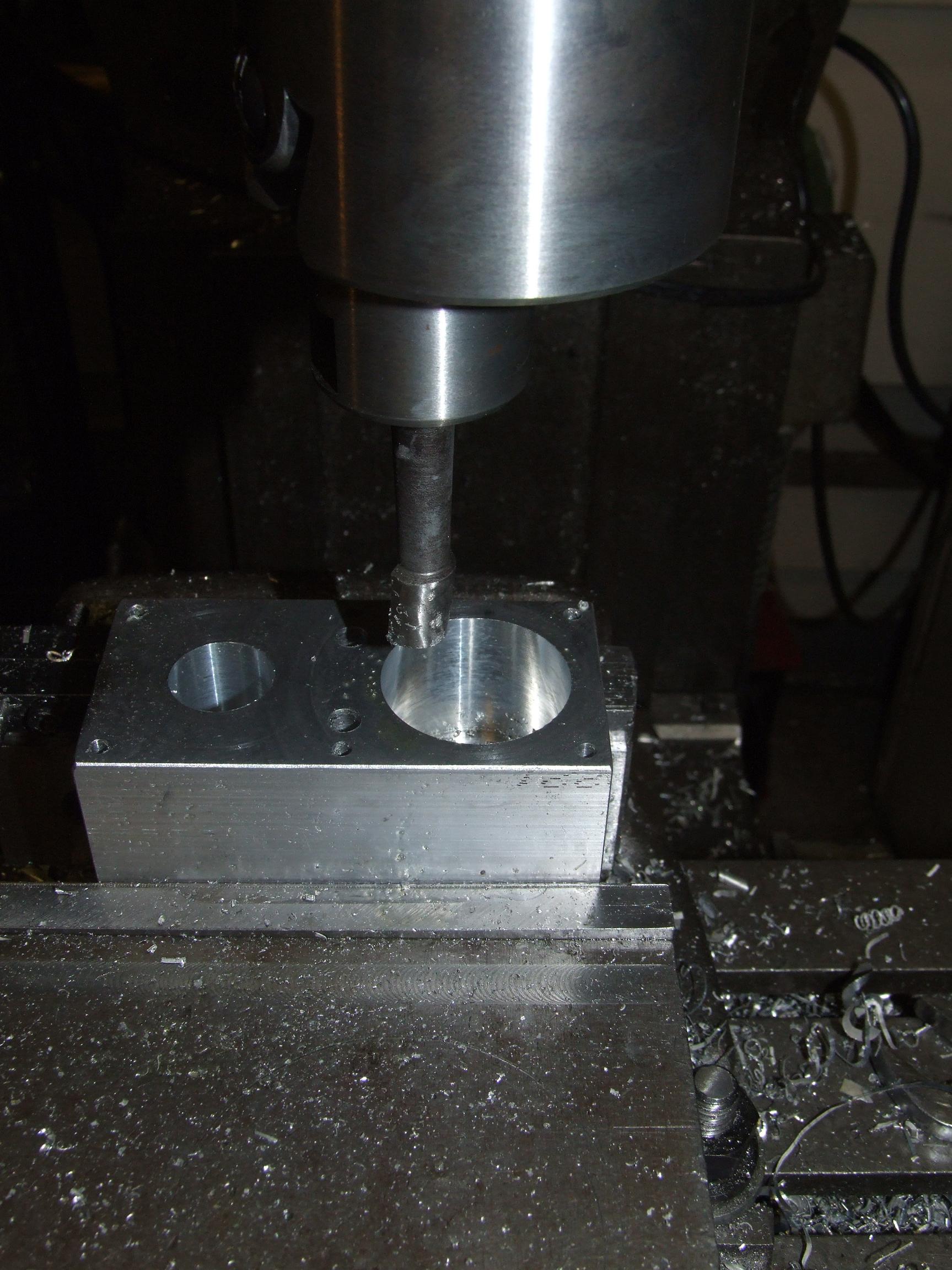
To actually be useful, the weird brass ring had to be removed from the motor shaft, and the whole thing needed to be shortened.

No problem, let’s just chuck the whole motor in the lathe and carve it all off in one setup. Again, this is one of those things that I put up just to make shop instructors cringe. Do not actually do this.

All done. The 15 tooth (rare!) pinions from the toasted motors were pulled off and reinstalled on these, with a dot of Loctite for trimmings. I say rare because only the 24:1 drill gearbox has a 15 tooth pinion, a gear large enough to actually bore out for the 5mm shaft of the Speed 700 motors.

The 24:1 drill gearbox is extremely uncommon in cheap drills. So uncommon that I have had trouble locating more for spare parts.

All mounted and ready. I’ve already cut the D-flats into the output shafts. These will engage D-flatted bores in the (still to come) final drive gears, and be retained by a single end screw.

Once I get said gears cut, the drive base can be assembled and theoretically tested. Next, to make a Siamese twin version of this gearbox – the Integrated Dual Frakenb0xen.

Überclocker Remix: Round Three; Pop Quiz and NK unofficially canceled

And the beat goes on.

The wire’s coming up fast.My summer internship with iLolbot ends this Friday. After that, I have a solid week where the only damn thing I’m going to do is plug on ‘clocker day and night. In precisely two weeks time, I’ll have to have everything wrapped up and shipped down to Atlanta. Lack of 24/7 tool access means that the state of the robot as of midnight on September 1st is pretty much going to have to be final.

At this point, I doubt I’ll have time to get to Pop Quiz at all. I thought Nuclear Kitten had required only a re-magneting, but it turns out the motor needs a total rework. Additionally, I need to reconsider the drive motors, since I went through two gearboxes last year and do not have any spares at the moment.

The insect status for Dragon Con is therefore tenuous.  NK is a second priority after Überclocker, and only if I think the design is going to be solid. Two events of last-minute rushing have sent me the message that last-minute rushing makes robots not fun.

Hell, if Überclocker doesn’t make it, I’m just going to D*C for the sake of going to D*C. Maybe I can actually take some pics this time.

Überclocker Remix

The build has pretty much reached the point where I’m the only bottleneck. That is, I have to fab all the rest of the part, and I’m slow compared to a CNC anything.

Yeah, I consider that “slow” now.

It’s time to start filling in the pretend-o-bot!

The “shocks” for the springy front legs. These are, like on Überclocker 1, post-op’d waterjet parts. I actually had to rework this design on the fly because I ordered the wrong kind of shoulder screws – 5/16″ diameter instead of 1/4″. The problem was that my springs had a 1/4″ rod-fit size.

Ever machine a spring? It’s not pretty, but a 5/16″ carbide endmill chucked in a lathe tailstock made pretty short work of it. I was expecting some epic disaster with the spring unwinding or just exploding out of the chuck.

This is the leg arrangement with the ‘shocks’ in place. I thought 100 pound/inch springs were going to be too stiff, but the high lever arm ratio of the linkage means the whole thing is still pretty bouncy.

More little shiny round things are now appearing around the robot. These are the drive “standoffs”, which function as dead axles. I formerly made these part of the robot structure, but it was an epic pain undoing the screws which held the body rail/panel to the standoff. Therefore, I just made a shoulder which sits in a bore on the outside walls of the robot. It’s not entirely structural, but will resist cave-ins (from impacts) to a degree.

I did end up putting a threaded hole on the outside end just in case I changed my mind.

The standoffs were made from 12L14 steel, which is something like two beans and a lollipop per six foot rod on McMaster. I have a new appreciation for this stuff – it’s like… steel, but it machines like aluminum.

Then again, how much should I be trusting steel which machines like fucking aluminum?

Hubs!

Well, these are actually functional prototypes of hubs. It was easier to pop four off in one cycle than to switch back and forth between machines, completing one at a time.

Completed hubs, with sprockets. Remember those sprockets with the weird double-D shaped bore? Now you know why.

Simple retainment and power transmission with the aid of the DD and a snap ring. I used to hate retaining rings (snap rings, C-clips, etc…) with a flaming magnesium passion. But after getting a set of snap ring pliers I realized they were the most compact and cheapest way to keep something axially where it should be.

So now I love snap rings. The cool thing is that the sprockets are easily removable, so I can press the wheel on later. This was just an assembly test.

… but wait, what do you mean the chain doesn’t go in my sprocket teeth?

I highly doubted it was a pitch/scaling issue, since some times the chain was able to wrap all the way around and other times not. I suspected that it was more a building up of small incremental errors made by the waterjet as the c hain went around the circle.

The solution was as simple as giving each tooth a really quick flick over the open section of a belt sander. After that, it was still sort of rough, so…

… this is TOTALLY LEGIT GUYS I PROMISE.

I am under no circumstances endorsing this kind of behavior.

Yeah. Right. Anyways, chuck one hub in a powered spindle of some sort (I had a convenient one 10 feet away), and put the other hub on a little axle that you can grab onto.Link the chain between the two sprockets and power the machine on.

Assuming you haven’t been sucked into the spindle yet, pull on the axle, hard.

This sort of grinds the chain into the sprocket teeth and forces it to round out imperfections just by virtue of being under balltastic tention. I was only limited in the pull force by the fear of the whole lathe rolling over onto me.

The sprockets ended up pretty smooth.

So I take back every mean thing I have ever said about 4 jaw chucks. They are wonderful, wonderful creations of man. More epic than the discovery of naturally-occuring sliced bread and the invention of the solar system.

But they’re still a bitch to use. However, it’s totally worth it for some situations.

Such as when you want to square off a section of barstock and insert a symmetrically-located circular feature in one setup! In fact, for situations (not speaking from personal experience at all) where your choice of barstock-portioning implement somehow makes an angled cut in two axes at the same time on both sides, the easiest way to get a known square end might be to cram it in a 4-jaw using the flat sides of the barstock and perform facing cuts.

I was only able to find tutorials on how to center round things online, but not square ones, so I had to invent my own little method first. Essentially it boils down to comparing the minimum deflection of a dial indicator on opposite sides and adjusting the jaws associated with those sides until they are the same. “Minimum deflection” refers to the location where the indicator tip is exactly perpendicular to the surface of the part. Any rotation would cause it to extend more.

…did I mention that 4-jaw chucks are a bitch to use?

Here are the results of a night bitching around with Bitch Chucks. These are embryonic drive gearboxes – more or less repackaged drill motors.

I discovered an annoying feature of one of my digital calipers which caused bore measurements to be .007″ under what they actually are. Imagine my surprise when I discover that a 0.944″ OD bearing passes through a 0.936″ hole.

It turns out the ID-measuring points were bent inwards such that they overlapped slightly.For future measurements I’m reverting back to an older (but less grunged) set.

This probably happened that one time they fell off a moving bike. Don’t ask why I have digital calipers mounted on a bike.