Face Vector Modulation Part II: Background and Theory

It all started in 6.131.

What caught my eye in the description was “go-kart controller”. I registered for the class back when I blew up a new LOLrioKart controller about once every month or so. I wanted to learn how to do it right. Lingering in the back of my mind was the little mention of 3 phase AC inverters, but I was reassured by classmates that it was just V/Hz control for an induction motor, i.e. not really that exciting. A legitimate control method it may be, but it wasn’t BLDC .

It all changed, though, when I received the assignment handout for the AC motor control. Here’s a link to a paper jointly written by the course professor along with associates, which details the apparati and methods used in the class. Pay particularly close attention to Figure 15.

So what does it do?

Space Vector Modulation

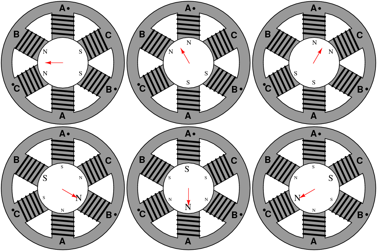
SVM is a control algorithm for generating 3 phase waveforms to drive motors. It is based off the simplest possible 3 phase AC motor, that which has 1 winding per phase and 1 pole pair (that is, 1 N and 1 S on the rotor). Such a motor has six states it can be in which are represented by 6 voltage vectors.

There are actually 8 total states, because if the three phase legs are taken to be either on (connected to V+) or off (grounded) and treated as binary digits, there exists all combinations of 0 and 1 from 000 to 111. Both 000 and 111 themselves produce no voltage across the motor, thus no movement, and are invalid states – observing the diagram on Wikipedoia, this corresponds to all the top switches or all the bottom switches being closed.

It is interesting to note that at no time are the top and bottom switches in a leg closed together. This would result in everything blowing up because the power supply is being shorted.

What this distills down to is that simple motor commutation can be achieved using a finite state machine model. A device with six (or 8, counting the zero vectors) states that steps through them in order will commutate an AC motor.

The class circuit provides this FSM functionality in the 74LS138 3-to-8 Multiplexer chip. In its legitimate life, it helped select peripherals for microcontrollers. Here, it takes the conveniently three-bit input and translates that to one output.

So that means if you put in a binary number valued 0 to 7 (000 to 111), you get one output Y0 to Y7 selected.

Now all that’s left to do is associate each output with the top and bottom switches. Observe in Figure 15 above how the OR (actually NOR, because the 74138 is an active-low chip) gates are each tied to two 74138 outputs. That means each output NOR gate is on for two sequential states, which follows the SVM rule of at least two switches, one top and one bottom, always being on.

/

So how does that correspond to the 3 phase bridge circuit? Let’s start at “state 1”. Motors are round objects, and to a degree you can fiddle with what’s called state 1. In state 1, Q1 is on. That means Q2 cannot be on, or things would smoke. So state 1 is Q1 and Q4 on, and the motor current goes in-1-out-4.

State 2 advances the motor to in-1-out-6, state 3 now toggles q1 off and turns q3 on, and so on.

  1. in-1-out-4
  2. in-1-out-6
  3. in-3-out-6
  4. in-3-out-2
  5. in-5-out-2
  6. in-5-out-4
  7. And the beat goes on.

The top and bottom switches are complementary and offset. The result in a motor is something trippy like this.

In the class circuit, the state switching is provided by the 74LS163, a 4-bit counter. In the lab assignment, we input a variable frequency square wave into the 74163, which sequentially stepped through its outputs from 000 to 101, 6 total states, then automatically resetting itself to 000 on state 5.

It is important to note that 000 and 111 here do not correspond to SVM states 000 through 111. The SVM 3 bit code is a Gray Code (of sorts), while the 74163 counts in raw binary. What the count from 000 to 101 does is select outputs 0 through 5 sequentially on the 74138. These output pins, in turn, go to the NOR gates and become commutation commands.

This was used as a crude VFD to turn an AC induction motor. The state machine sets up a rotating magnetic field in the motor, and it turns.

Oooh, shiny.

Face Vector Modulation

I wanted more.

I immediately saw how the simple SVM kernel could be used to run a brushless DC motor. Your average brushless DC motor has 3 Hall Effect magnetic sensors that pop high and low depending on the position of the magnetic rotor.

Wait, 3 bits?

This could get exciting.

Face Vector Modulation, Part I: Motivation

Everybody knows that I love brushless motors. They have essentially taken over DC brushed motors in just about every high performance application by virtue of being much more power dense and efficient. They have a fundamentally stronger physical construction (no spinning bundle of wire), less friction (no brushes), are simpler (no commutator), and can spin at speeds in the six digit range.  And are just… awesome.

And adorable.
And adorable.

What’s not awesome about them is control. A DC motor can be controlled by touching wires to battery terminals. A brushless motor opts to replace the mechanical segmented commutator with power semiconductors, control logic, and embedded software.

Wait a second. I hate software, semiconductors, and control logic. Those are electronics. They are my archnemesis. I want my DC motors back.

Historically speaking, control has been one of the roadblocks to widespread BLDC adoption by hobbyists. The issues of motor control are inevitably tied into motor application. There are a few characteristic traits represenative of the majority of BLDC motor controllers that are for sale to the general public:

  • They tend to be very optimized. R/C airplane motor controllers are cheap and power-dense, but being built for use with R/C equipment, they are completely run by (and calibrated by) the industry standard 1 to 2ms pulse duration modulation signal. They are designed for low torque (and shock), high speed loads, like a plane propellor, and have very poor torque characteristics otherwise.
  • “Industrial” controllers tend to be massively built and extensively featured. Field oriented control, precision tachometry, programmable curves for every variable motor parameter, feedback and servo amplification – you name it. The net result is “EXPENSIVE”, and usually low powered, for reasons including the fact that industrial motors tend to do the same thing all the time.
You have too many wires.

I approach this from the perspective of small electric vehicle hacking. Using BLDC motors in drivetrains presents issues which are (usually) not present in either a model aircraft or industrial setting:

  • Widely varying torque and speed requirements, especially high torques at low speeds
  • Shock loading and sudden disturbances
  • Commandable reversibility

Many small EVs such as scooters and bikes have been built with model aircraft controllers, including mine, and suffer from  the problem of launching from standstill. These controllers are what’s known as back-EMF commutated or sensorless controllers. They require the motor to be moving a bit so they can sense the phase voltages in order to know where the rotor is. A slight chicken-and-egg issue if I may say so myself. So unlike DC brush motors, you can’t usually stand on one of these and just take off. Motors with rotor sensors, usually Hall-effect type, and the controllers that can read them, can much more closely emulate the torque curve of a DC brush motor.

The other problem is one of signal interfacing. Because they are designed as black boxes, they are compatible with the industry standard, 50 hertz refresh rate 1 to 2 millisecond duration command pulse used by servo motors and receivers. The vast majority of EV throttle interfaces just use a potentiometer to output a varying voltage. To bridge the two requires some degree of electronic trickery or software hackery, or a product such as a servo tester.

The third problem with model aircraft controllers is their annoying startup and calibration routines. In the field, pilots tend to have exactly one tool to communicate with the model – the transmitter. Consequently, elaborate systems of changing controller settings involving varying the stick position (i.e. pulse duration) exist. So if your signal interface is even marginally wrong, the controller may become confused and not run at all. The majority of these settings only product noticeable effects at high RPMs.

What the fuck is this shit?

Recently, companies such as Kelly Controls have introduced low-cost, EV specialized controllers that address both the sensor and interface shortcomings. Besides being of questionable quality, however, the controllers tack on all sorts of frills that are useful only to legitimate EVs, such as contactor drivers, reverse beepers, light controllers, programmable throttle and brake curves, current limiting, etc. While nice to have, they are overkill for most small one-offs like scooters and e-bikes, and are enormous for the power they handle.

At the end of the day, I just want something that will run my Robot Jesus damned motor. It doesn’t have to do it with maximum efficiency, nor with minimal torque ripple, nor with phase current control. The best thing in the world would be a model aircraft ESC, with its extremely high power density, crossed with an EV controller that uses sensored motors and an analog throttle.

The goal of Face Vector Modulation is to produce a hardware kernel that will commutate a brushless DC motor with Hall-effect rotor sensors. It should not require specialized parts, proprietary ICs, or programming microcontrollers. This kernel can be extended and built upon, like an operating system kernel, to produce an EV (or robot, or bizarre kinetic sculpture) controller of the builders’ choosing, to arbitrary power limits.

The goal of a controller that I will make using the FVM kernel will be a small EV traction drive that can operate from 0 speed to the maximum speed of a not-yet determined motor, have high torque at low speeds, and interfaces to the user through a standard 5 kilohm throttle potentiometer.