So after the last wheelmotor build worked but failed miserably, I paused effort on it for a while as classes started again, TB needed prepping for Motorama ’08, and the Media Lab beckoned. However, with springtime approaching, I’m picking up the build where I left off.
There will be a few changes made to the design.
- Forget “minimal chassis modification needed to install”. Who the balls am I building this for anyway? A minimal chassis modification for me might as well be building a whole new back end.
- This allows me to use a wider motor. The diameter will not change much since it will still go inside a 5″ wheel. However, torque is proportional to motor length, all other things held constant, so I hope to get some more push from this next build.
- Also, I will use a real stator. Waterjetting .032 steel plates, coating them in wood lacquer, and slamming them on a hub doesn’t really count as having an iron core stator.
- The stator will have fewer, larger poles. Torque is pretty much determined by how many amps you can shove through how many windings, and for a motor of a given diameter and power rating, there’s only so much that adding more poles can do. Beta #1 was almost a stepper motor. I will never push either motor to its maximum electrical speed as dictated by the ESC anyway, so by using larger poles I can shove more windings in.
- The magnets will be ginormous. I settled on some 3.5mm thick,15mm x 8mm rectangular N50 magnets this time around. Each will be stacked end to end to give a single 30mm long metamagnet.
Hopefully the above combinations will make for a better drive motor. Just about anything will be better, actually, since eddy current losses were probably through the roof with my ghettorunner.
Some work pics over the past week or so:
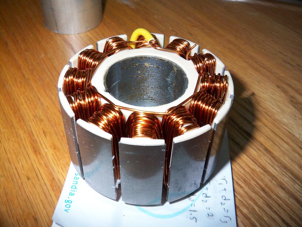
 The stator of choice was harvested from a large Kodak copier’s main drive motor. I actually stole this from said copier a while back when it was placed up for grabs as a freebie. I snuck into the building during the early morning hours, dismantled the copier, took out the motor, then put everything back together, leaving no trace.
70mm diameter and 35mm high, but unfortunately I cannot use all of it since there is no space (I don’t actually intend to rebuild the whole back end!). So it will be separated into two pieces, one 25mm for my use and one 10mm for wall decoration.
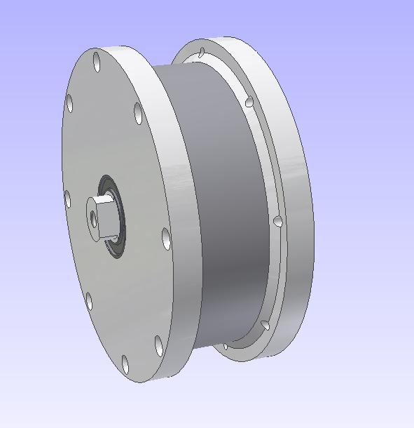
 Rendering of the new motor. It is a full 46mm wide, which is almost twice as wide as Beta 1. The middle shaft also sticks out a bit for easier mounting. Also, the wires will no longer exit through the hollow center of the shaft. Instead, they will pass through a gap between the shaft and the bearing. This will make installation significantly easier.
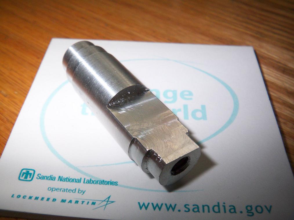
 The center shaft. This was made on the lathe using NEW TOOLING! WHEE! and then milled. The stator mount will end up flush with the end of the flat, and so the wires will be able to exit directly, without snaking through holes and the centers of screws.
 For the next step of the process, I had to bore a precise hole. This was rather hard, since we don’t have a boring bar. I snaked around this problem by grinding one of the new carbide tipped bits down to approximate a boring bar. It actually ended up working, to my utter surprise, though there were rough spots.
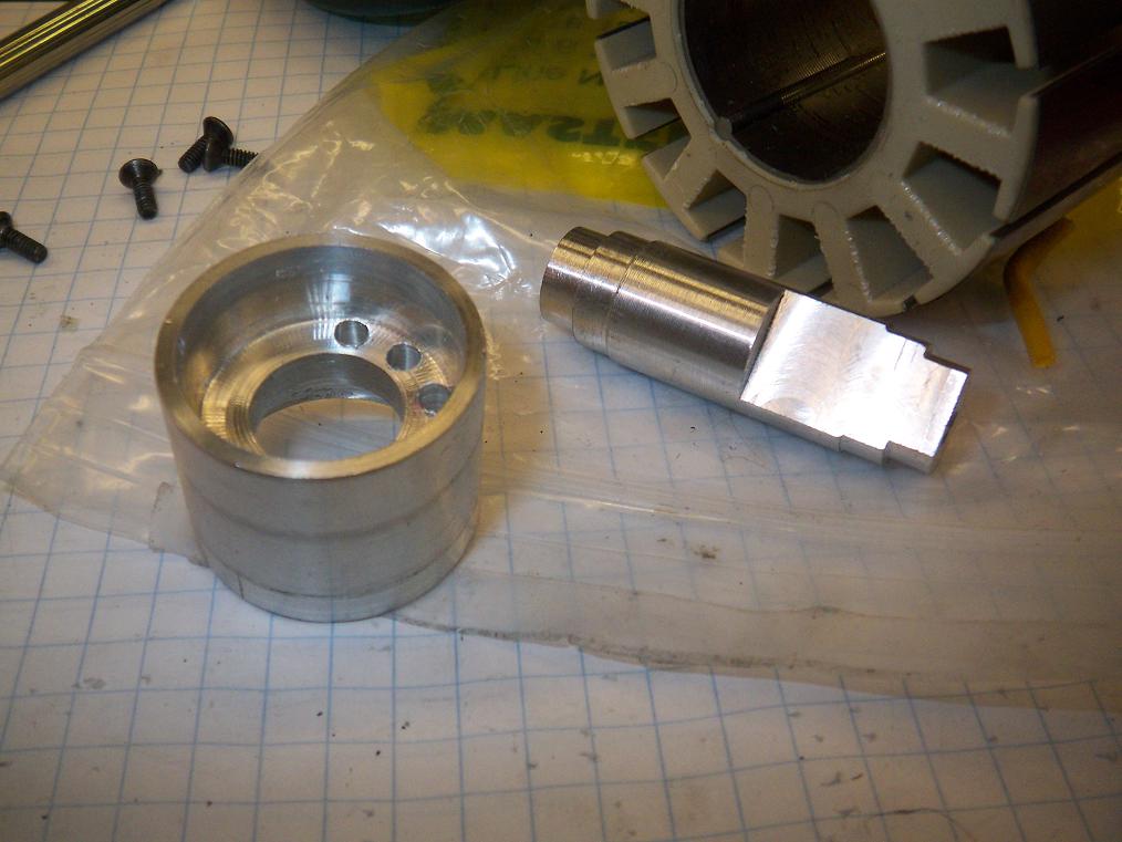
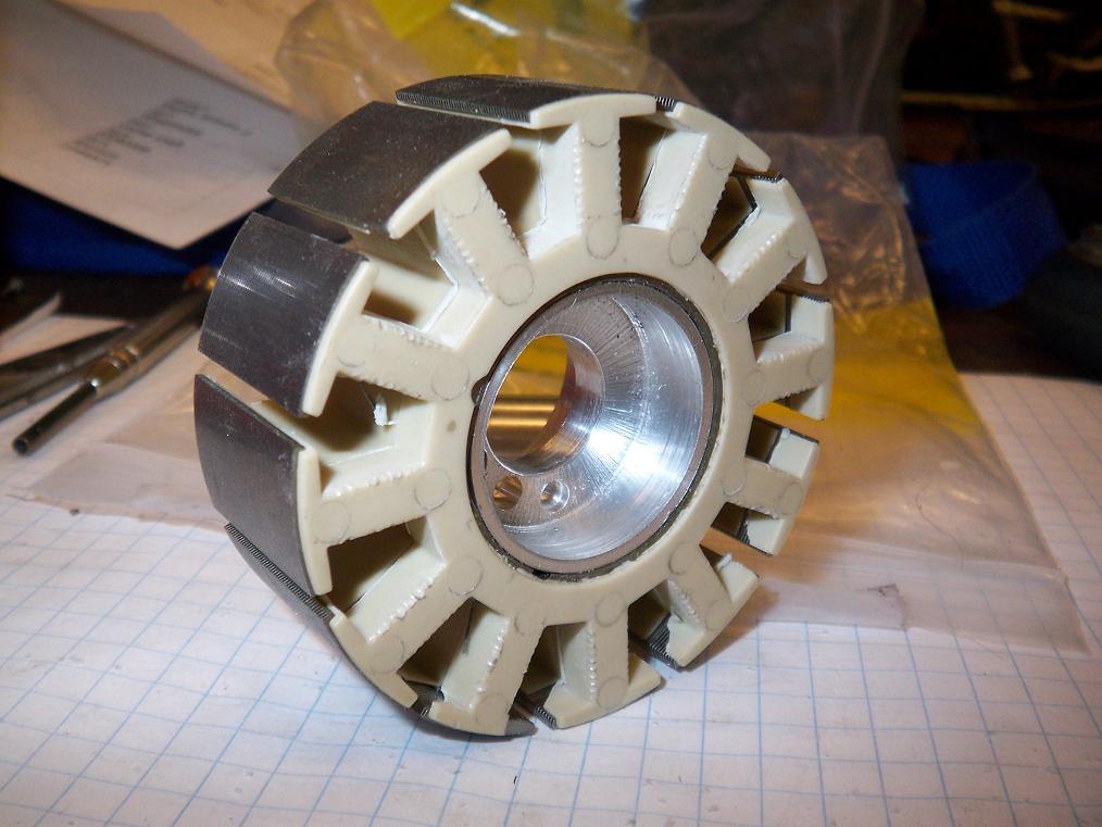
 Here’s the product of said boring bar, a press-fit hub for the stator. The three holes are to guide the power wires so they can be connected to the windings. This hub, in turn, will be pressed onto the shaft.
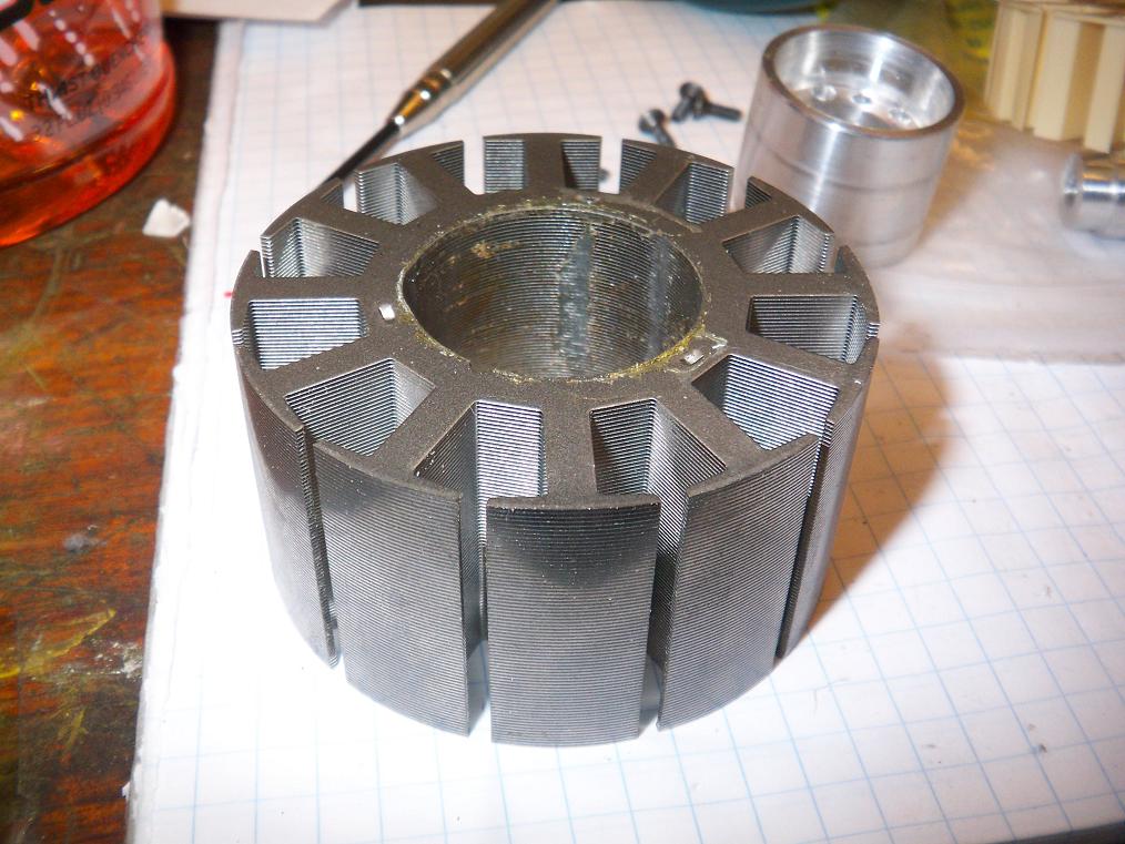
 Stator stripped of wiring. This was an amusing process – loosen one wire, then drop the stator, letting the wire unwind as it flails in the air. Repeat 3 times. It almost resembled a fish flailing in the water resisting getting reeled.
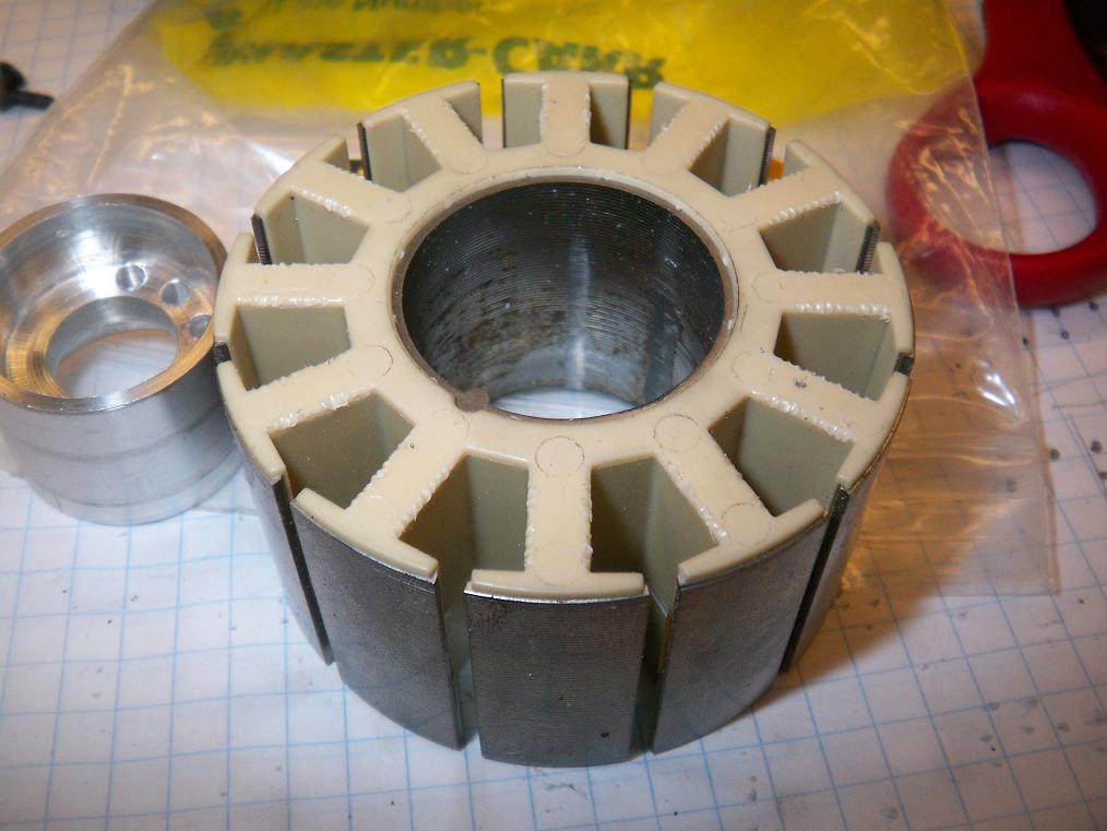
 Plastic endcaps removed from the stator. I tried my best to keep them intact, since having insulative caps would help the winding process immensely.
 Next, I had to trim the 10mm off the stator. This was the most disaster-prone part of the evening, and required the most setup, but it actually went smoothly.
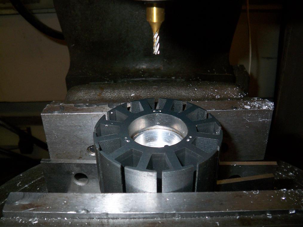
The stator, with hub pressed in, was mounted in a milling vise, sitting on parallels. With a NEW EDGE FINDER!!!!!!!! the center was located. Then, using an 1/8″ endmill, I mill/drilled one of the crimp-like things which held the stator together. One by one, the laminations fell off as I drilled deeper.
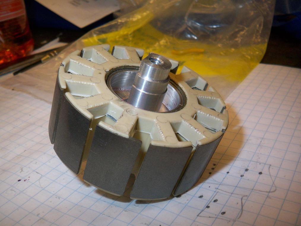
I set the quill stop at the height of the hub, so the final product was a clean 25mm stator.
 I think this is some of my best machine work yet.
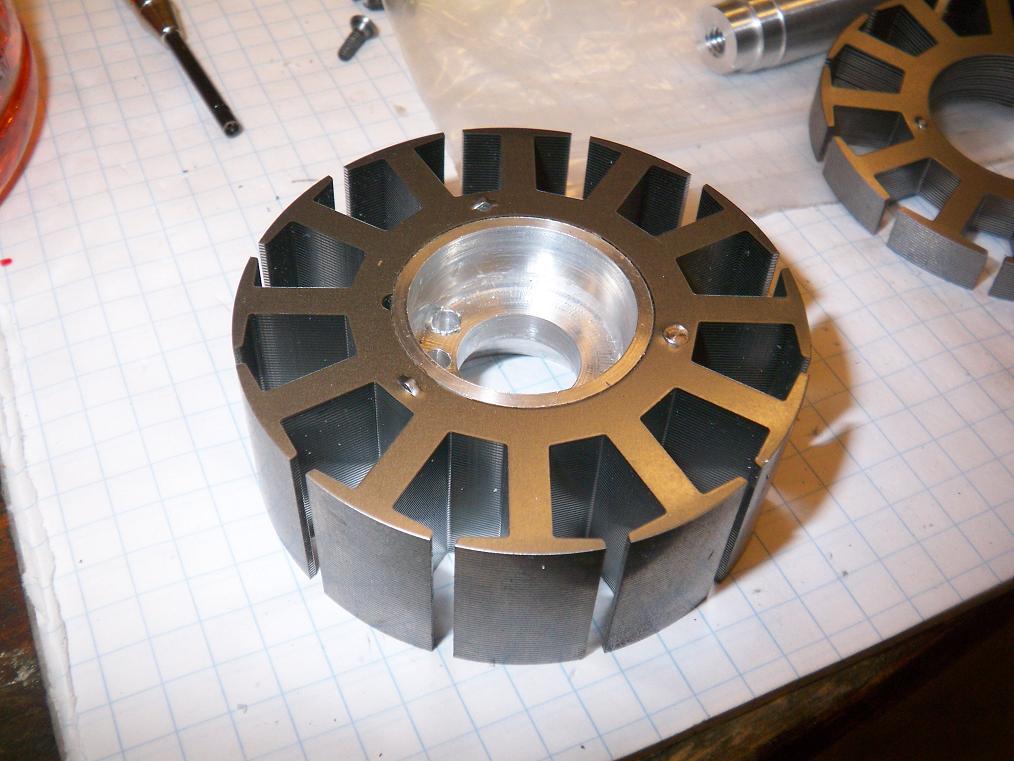
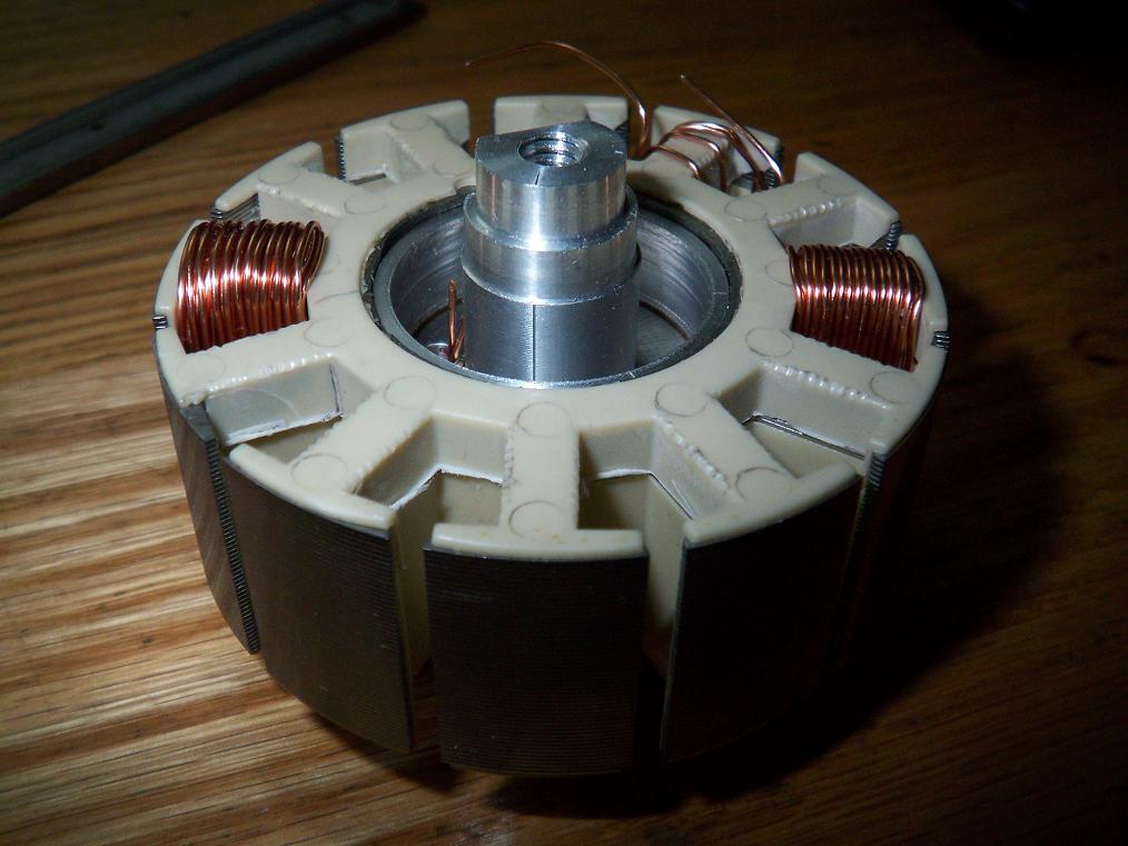
 The plastic endcaps were now a few millimeters too long. They’re also thin, floppy, but brittle at the same time, so that precluded most methods of trimming them (scissors, cutters, milling, etc…). I ended up holding them to a belt sander for a few seconds. Worked great, but a few bits still came off, so this side looks a bit grungy. The key part is that the stator arms are all insulated.
 Shaft mounted in the hub, with plenty of Loctite for security and the fancy fruit-like smell. This whole thing is now one unit, like Beta 1. I thought about making removable mounts, but decided it wasn’t worth the effort.
The next step is to machine new side plates to accommodate the wider motor. Then, I need to find a chunk of steel pipe to turn into the motor can, onto which magnets will be mounted. It turns out 28 of the magnets mentiond at the beginning, lined side by side, fill up the motor can to within a millimeter of circumference, so I’ll probably be winding the motor “LRK” style, with 14 magnet poles. Each magnet in this case is four small magnets.
Stay tuned!


 Â Testing windings. On the right is 30 turns of single-strand #22 wire. On the left is 30 turns of double-strand #22 wire for an effective winding gauge of #19. I haven’t settled on a particular winding yet. That will come after some math, testing, and stretching the R/C hobby builder rules of thumb to the edge of existence. I will probably end up winding this motor alot milder than the last, and run high voltage.
 Testing windings. On the right is 30 turns of single-strand #22 wire. On the left is 30 turns of double-strand #22 wire for an effective winding gauge of #19. I haven’t settled on a particular winding yet. That will come after some math, testing, and stretching the R/C hobby builder rules of thumb to the edge of existence. I will probably end up winding this motor alot milder than the last, and run high voltage.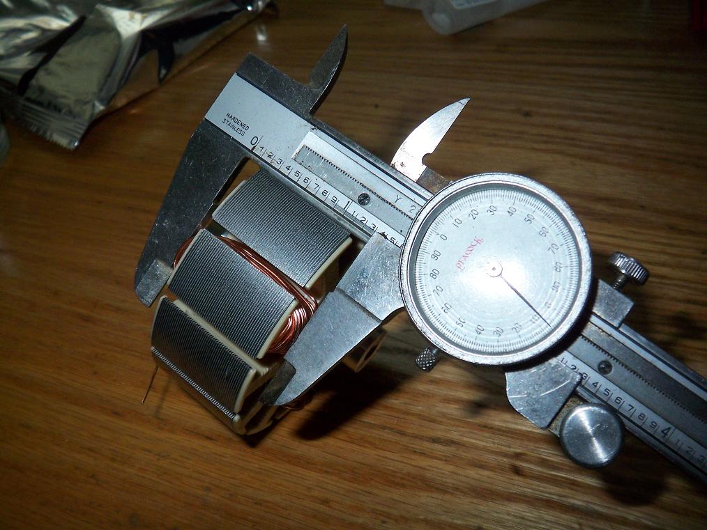 One thing that attracts me to keeping the 30T of dual-strand #22 is that everything works out perfectly in terms of fit. I’m left with a little more than .025 clearance on both sides with the winding ends accounted for. That means I can wind the motor, then stuff the whole thing in a vise and squish down the windings some and not have to worry about wire clearance.