Despite the fact that winter is fast approaching and in all likelihood I won’t be able to actually use what I build until I emerge from hibernation, I’m pressing on with the design and build process. The goals of this build are:
- No wheelying. Snuffles 1 went from offhand build project to prototype, and the prototype will be refined to avoid death as much as possible.
- Stealth appearance, in a sort of Monster Garage way. The only thing visible on the outside to indicate that it is electric should be some cables. This implies…
- Wheelmotors. I’m going to shove as much power as I practically and theoretically can into those little 5″ scooter wheels.
Over the past few days, I evolved the design of the wheelmotors significantly. The previous 12-slot motors were ditched because they, power for power, spin too quickly and generate too little torque. Since there will be no gearing besides the virtual reduction of the motor, torque is a desired quality.
Second, I did away with the axial design completely. The space I can fit the windings radially was about as much as I could fit them axially. Theoretically, the redial (normal) configuration would produce the torque all at the rim where magnets meet windings, whereas an axial motor distributes its torque production over a range of radii. The radial design also allowed me to get as close to the outer rim of the wheel as I could. More radius, more torque.
The design of the motor boiled down to two separate paths. One is pretty much what is found in your average BLDC motor as seen on the bots and on model airplanes. In essence, I’ll be making a giant outrunner that happens to have a wheel on it. This is easy, I’ve done it before, and it’s proven to work.
The other is a completely off-the-wall never-seen-it-in-my-life got-the-theory-from-websites design. I don’t even how the proper terminology to describe it. Either way, it’s a slotless type motor that unlike the aforementioned conventional BLDC, doesn’t have wire loops that form solenoid-like pieces. Instead, it relies purely on the Lorentz Force generated by running current through a wire passing through a magnetic field. Most serious commercial motors that are ironless use a design like this, and have insane power-to-weight ratios. This is something that requires a degree of precision I haven’t personally experienced before and is purely “ooh, shiny” to me at this point. Not even theoretical, because I don’t have EE/E&M experience to know the theory.
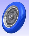
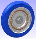
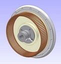
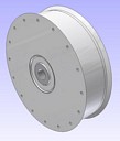
Now some pics of the design.
The Conventional, Simple, Maybe Well-Executed Design
Here it is. 33 stator slots and 34 magnet poles. This one-more-magnet configuration allows for some interesting winding tricks, and should yield a “virtual reduction” in the 16-18:1 (relative to a 3-slot 2-pole motor). I will waterjet-cut the core assembly out of lamination steel if I can find some, or plain steel with appropriate insulation if not. My eddy current losses will probably be out the ass, but hey, it’s something.
The Off-the-wall Farfetched WTF-is-this-Shit Design
This is the inside of the “other” design. There are now TWO magnet cans, one inside and one outside, surrounding a (representative drawing only) cup-shaped winding, whose support structure isn’t visible in this picture. The two magnet rings are both installed firmly on one of the hub plates of the wheel. This is more or less an average axial pancake motor but turned 90 degrees. It really isn’t that bad to build, but just needs some touchy alignment of the winding core which, bring fully surrounded by copper, has no mounting option but epoxying it onto the support structure. This offers the most torque of anything so far,and can’t really be compared to the motor design above. If you’re really interested, google stuff about axial-flux 3-phase motors some time.
A pic of the core assembly. The stator cup is held solidly on the shaft, which is nonrotating (the wheels and magnets rotate around it. The plate it’s mounted on is one of those hub plates. The advantage of this design is really dense packing of the copper strands, moreso if I’m willing to put up with more headaches and use many strands of fine wire to fill all the space available.
The dual-magnet-ring assembly. The aluminum can has little nubs designed in it such that the magnets press in and are fixed at a particular location. I just have to make sure they press in correctly, or there is no turning back. Again, this isn’t that complex, but is one more thing to machine.
The outer case of the motor is made of two pieces, an aluminum can and the top cover. Notice the odd resemblance to the exterior of a car tire’s rim. You know what I’m thinking if this crazy plan works, and I do too. Hmm.
That’s all for now! Let’s see if anything actually gets built.


