Tinytroller: It trolls!

First, some very important things:

Anyways, back to Tinytroller.

Over the past week, I’ve been intermittently debugging Tinytroller by scoping everything, replacing potentially damaged components, and carefully looking over my board layout and schematic to see where problem spots could exist. And considering ditching the Arduino…


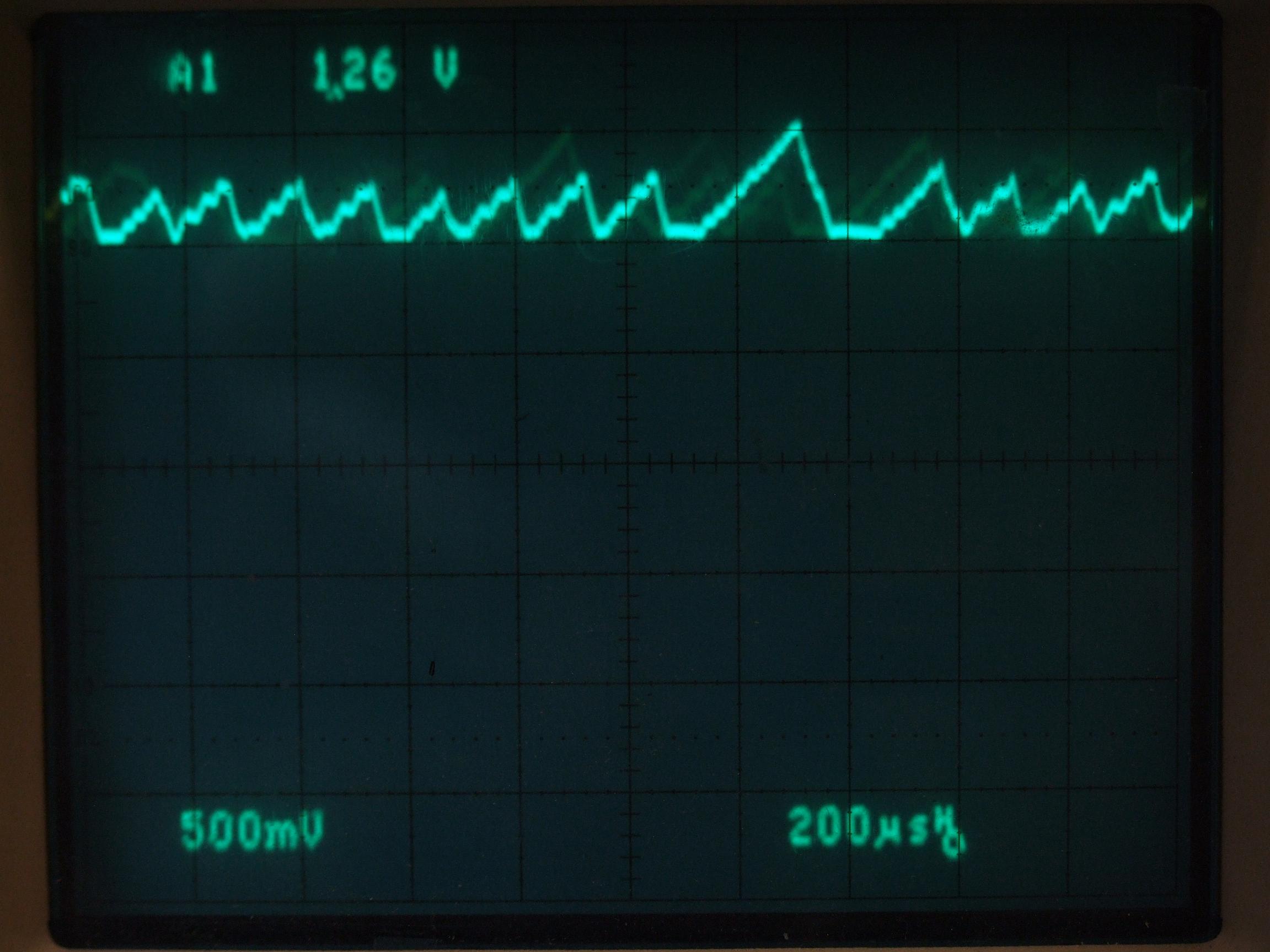
When your gate drive power bus looks like this, you know you’re boned

I’m proud to say that after hours of scoping around and trying various bridging and bypassing and filtering tricks, the problem turned out to be a faulty ground connection which was very high impedance, causing motor switching noise to couple into the logic, causing the microcontroller to crash and reset.

another. software. problem.

Is it any wonder why I hate software?

The problem lay in (of all things) my debugging code, which printed several values (such as the PWM command, motor state, current sensor readings, etc.) over serial. I figured Serial calls on the Arduino just threw your bits and bytes into a buffer and went on. As it turns out, it does, but it will sit there and wait until all said bits and bytes have cleared the buffer, because the buffer is only 1 byte and transmitting ASCII characters takes up far more volume in terms of bytes than transmitting the numerical value of something. All told, with 4 or 5 int values and newlines and tabs being turned into ASCII and transmitted over 38400 baud serial, something like 7 millisconds of loop time was being taken up by the ATmega chip playing with its own serial port.

It turns out that servicing your Hall sensor polls 7+ milliseconds late means the motor has already moved on and you may just be changing states into one which is totally incompatible with the flow of current. This, of course, would drive high voltage and current transients back into the system and cause it to crash or explode.

I am certain that some noise problems may have been eliminated from the original interrupt-driven code version through the splitting of grounds, the addition of fast TVS diodes on the 5v line, and more logic capacitance; but the vast majority of crashing and burning was caused by inadvertent delays introduced through the Serial communication.

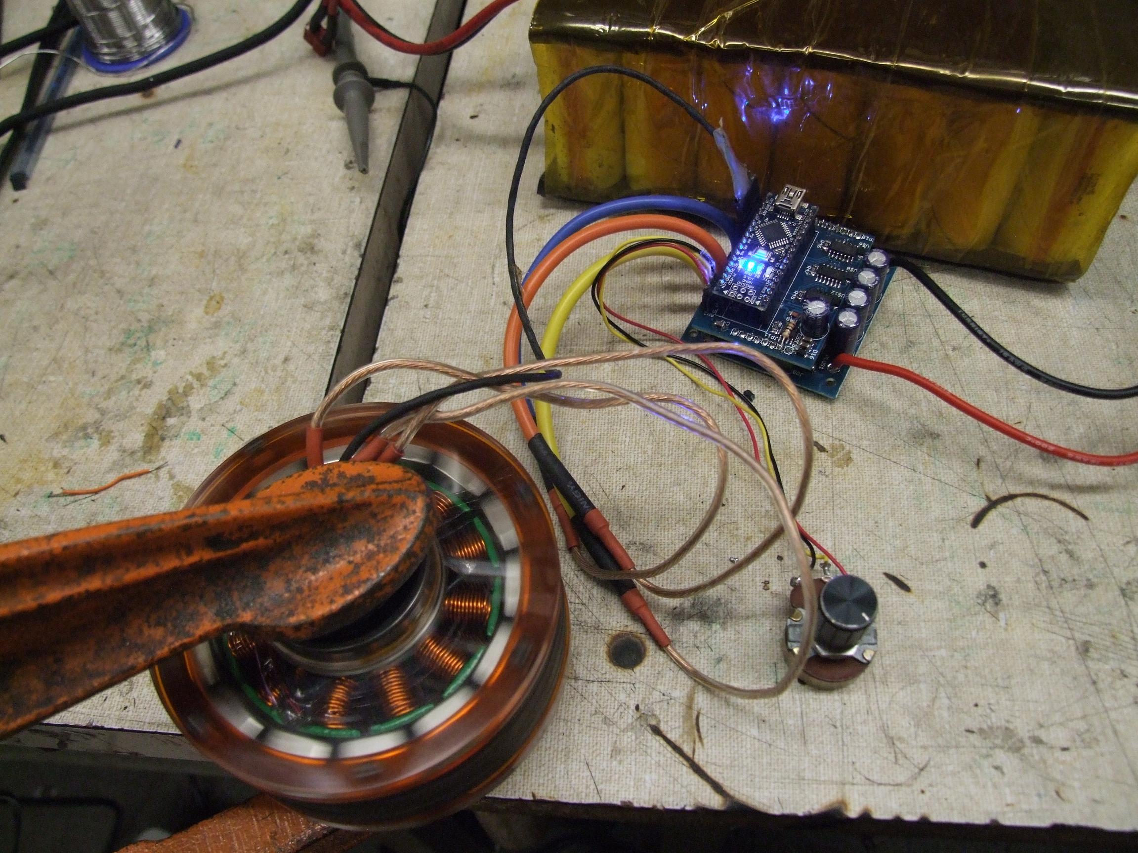
Whatever, it works. In fact, it works great. I got Tinytroller running on ported Melontroller code, so it at least puts me back in the black in terms of controller progress – once again, I had an Arduino-powered object that vaguely makes a motor spin. I was able to play with Kitmotter (shown above), and also ran the MITERS Public Etek on a regulated power supply since I didn’t quite trust it on a battery (source of infinity DC amps if needed) yet.

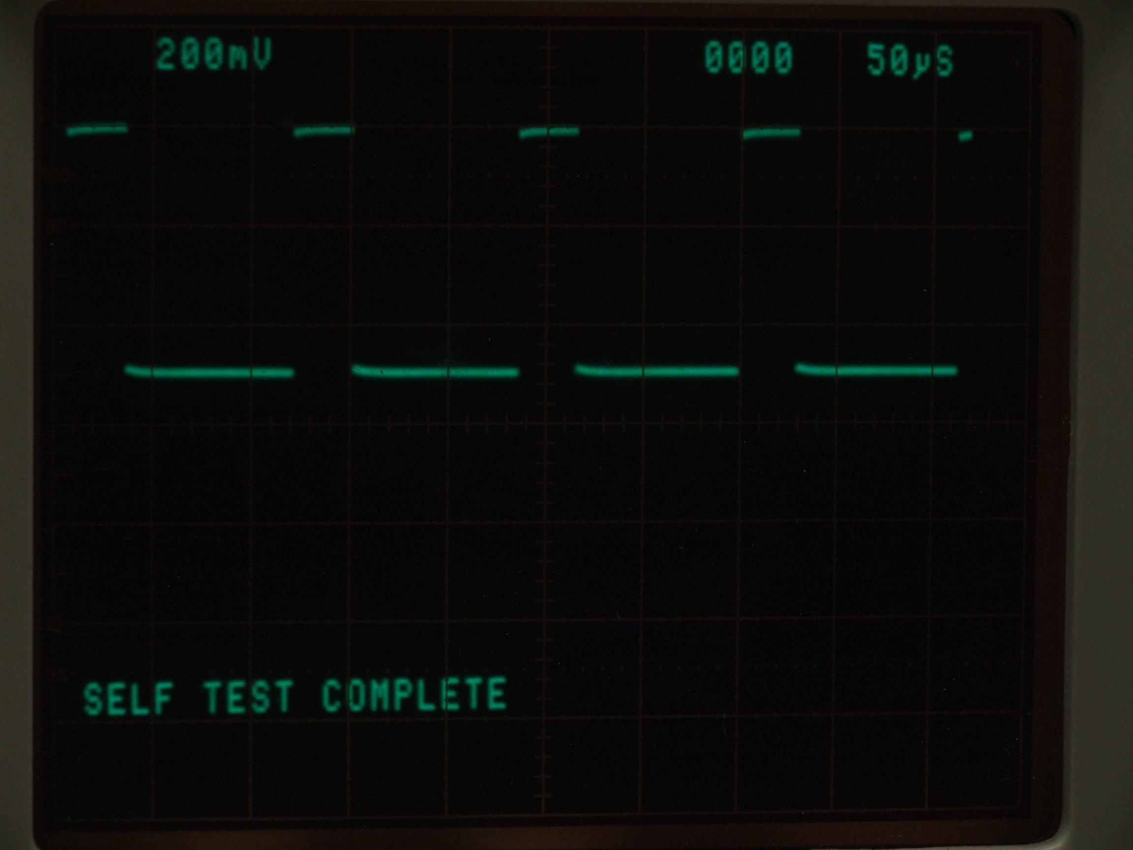
I next put the interrupt-based code back on. And guess what: without those Serial writes blocking traffic, it worked just fine. The interrupt is shown above running at 8kHz and with the pin reads and state table taking up still about 20% of the time. I noticed a small amount of weirdness at low throttle values which made the motor run slightly louder as if it were less well timed, but otherwise did not seem to affect operation or draw obscene currents. Adding various amounts of delay in the ISR  (10 to 60 us) caused the “weird period” to move up and down within the range of throttle values. I suspect this may be due to internal events such as the output compare register resetting running into my interrupt service routine…. or some other weird software shit.

Either way, I was unwilling to sacrifice future valuable microseconds in this ISR, so I left it as-is since the weirdness only manifested itself at very low speed.

Without further ado, Tinytroller: The Video!

The scope shot is zoomed in on the ISR, and shows it taking up very small increments of time depending on how far through my state table it had to fall before finding the correct one. However, it seems like 90+% of that time isn’t rummaging through the states at all. Hmmmm….

Regardless, I’m satisfied: If it can hard-brake the Etek from full speed (granted it’s from 25-26 volts only) to zero in under half a second, that’s a pretty stiff introductory transient test.

Next, with Tinytroller having reached the same level of functionality and robustness as melontroller, it’s time to do that thing I said I would never do: write the current-mode controller software. It’s time to add a flywheel to that Etek.


RazEr rEvolution Repaired… with Sensorless Jasontroller

I’m sort of in love with these Jasontroller things lately, honest. I guess it’s because it temporarily relieves me from buggy controller duty and it’s already better than anything I foresee myself building in the near future.

The last time RazEr was mentioned, it was rolling on nice new wheels but with a miniature house brick stuck to the back half of the deck. That’s the sensored shady e-bike controller that I picked up in Singapore. For a while, I had bounced around the idea of just mounting the thing inside. The board in those controllers isn’t that large – it’s the aluminum case that comprises most of the volume. But I ultimately took the controller off, tossing it in the box of EV parts, and RazEr was left a dummy for a while…again. This being the semester I have devoted to making sure more of my projects were working instead of starting endless new ones, I decided to dig it out and investigate everything again.

Embedding the controller was only possible if I switched batteries to something with better packing density. The A123 26650 cells are nice, but they’re not the best if I need more volumetric energy density since there are huge gaps between the cells, even in the “close pack” configuration.

I started playing around with various arrangements in CAD and in real life. I used some spare surplus 18650 type Li-ion types to gauge just how many cells I can stuff into RazEr while either maintaining or improving my pack capacity. I could, in fact, fit a 3rd “row” of 18650 cells in the center of the frame where there is a cutout in the aluminum structure. With 16 cells per row, I could maintain a 12-series (38.4v) pack.

Testing with the Sensorless Jasontroller revealed that it handled RazEr’s hub motor extraordinarily well. It was significantly quieter and smoother without sensors, which boggled me for a while – but the sensors in the DNIR are known to be placed with some angular alignment error. Sensorless commutation also seems to let the motor run at the speed it “wants to” instead of forcing it to be hard-switched by changing sensor states, especially if those sensors are mistimed. So the decision was made to drop a 350w type Jasontroller into RazEr instead, and keep the sensored controller around for other, more mundane tasks, like Kitmotter.

The actual cells to be used are A123 18650 cells, each of 1.1 amp hours. While it’s not like one of those brand spanking new Panasonic 3Ah 18650 cells, these are much less likely to set on fire and are more tolerant of abuse, because A123 . The actual pack is roughly 1.5 inches shorter than the 26650 pack and with 4 cells in parallel, I don’t really lose any capacity.

I really like these cells, because not only do they pack better, they respond better to Angry Soldering Iron. They’re definitely much easier to solder, and I really had to exercise my touch-and-go battery soldering. The upside of making a ‘strip pack’ is the fact that I get to drop a single piece of braid across 8 cells and have a 2-cell, 4-paralle string in the end. This pack went very quickly – in fact I spent more time making those damned balance connectors.

The linear arrangement also lent itself well to routing the cell balancing taps between conductive things in order to avoid accidental balance wire deflagration syndrome.

After finishing, padding, and heat shrinking the whole thing, I got to see how well the new pack fit into the frame. The cell parallelogram is arranged such that the bottom layer is furthest forward, which gained me another half an inch or so to play with on the lower half of the frame.

A gutted and cleaned Jasontroller is also shown in its quasi-final location. I’m just going to seal the board and then mount it to the frame via the MOSFET heat spreaders.

I used the heat spreader bar as a template to drill holes into the frame such that the board was out of the way of the battery and also did not contact anything it wasn’t supposed to. 12mm long M3 socket head cap screws were used to attach the controller to the frame.

And the controller is mounted (but not sealed in Goop or anything yet). I ended up making new leads for the phase outputs since the existing ones weren’t long enough to reach under the board and out of the Hole of Wire Clearing. I laid some silicone heat transfer compound between the heat spreader and the frame, so it should have the entire frame now to warm up.

I elected to leave this 350W Jasontroller unmodified power semiconductor-wise, but jumped the shunt to 1 milliohm in order to bring the power output up to par with the DNIR’s capabilities. On a Wattmetered run, I managed to pull 1200 watts from the thing – so close enough to 1milliohm it is.

RazEr now pulls hard enough that it will almost wheelie if I’m not careful. Right now, it is almost on par with melonscooter for speed – which admittedly is a little frightening.

And the final ‘press shot’. Maybe I can even install a real switch again!