Make-a-Segbearshark: Random Updates

With the holiday and end-of-year business shutdowns finally ending, the steady trickle of parts shipments for Landmelonsharkpigbeartankboard is flowing once again. I’ve finally gotten my trippy PCBs in for Make-a-Bot too, but haven’t gotten the chance to make the heat spreading plate and test it yet. Otherwise, I got Segfault running once again, now with its own enormously overkill battery.

Overall not much to say, so let’s just start with the grocery list.

landbearshark

LBS is still a pile of parts that has been steadily increasing in size. The materials needed to start the entire project off are the aluminum plates, which have yet to arrive. Otherwise, I have essentially everything – motors, motor-side sprockets, chains and links, the four shock bodies, a whole mess of stainless steel hardware, most other drive components, and this cute little contactor.

Here’s what the whole mess looks like right now…

Still on the way for whatever reason are three 24″ x 24″ x 1/4″ aluminum slabs. Other frame materials are used in small enough quantities to just be scrounged.

The design has been filled out with the requisite t-nuts needed to hold the panels together.

Some minor touches are missing, including places to mount the rider-sensing switches. The contactor and other major electrical components are also homeless at the moment. I also need to make the “second deck” of electronics which will handle tasks other than motor control. I did collect a model of the Giant Red Key Switch, and it hangs out in the back.

If I’m lucky, the metal will arrive tomorrow and the frame can be cut out by the weekend. That’s really the only hard part.

(Okay, minus the electronics…)

make-a-bot

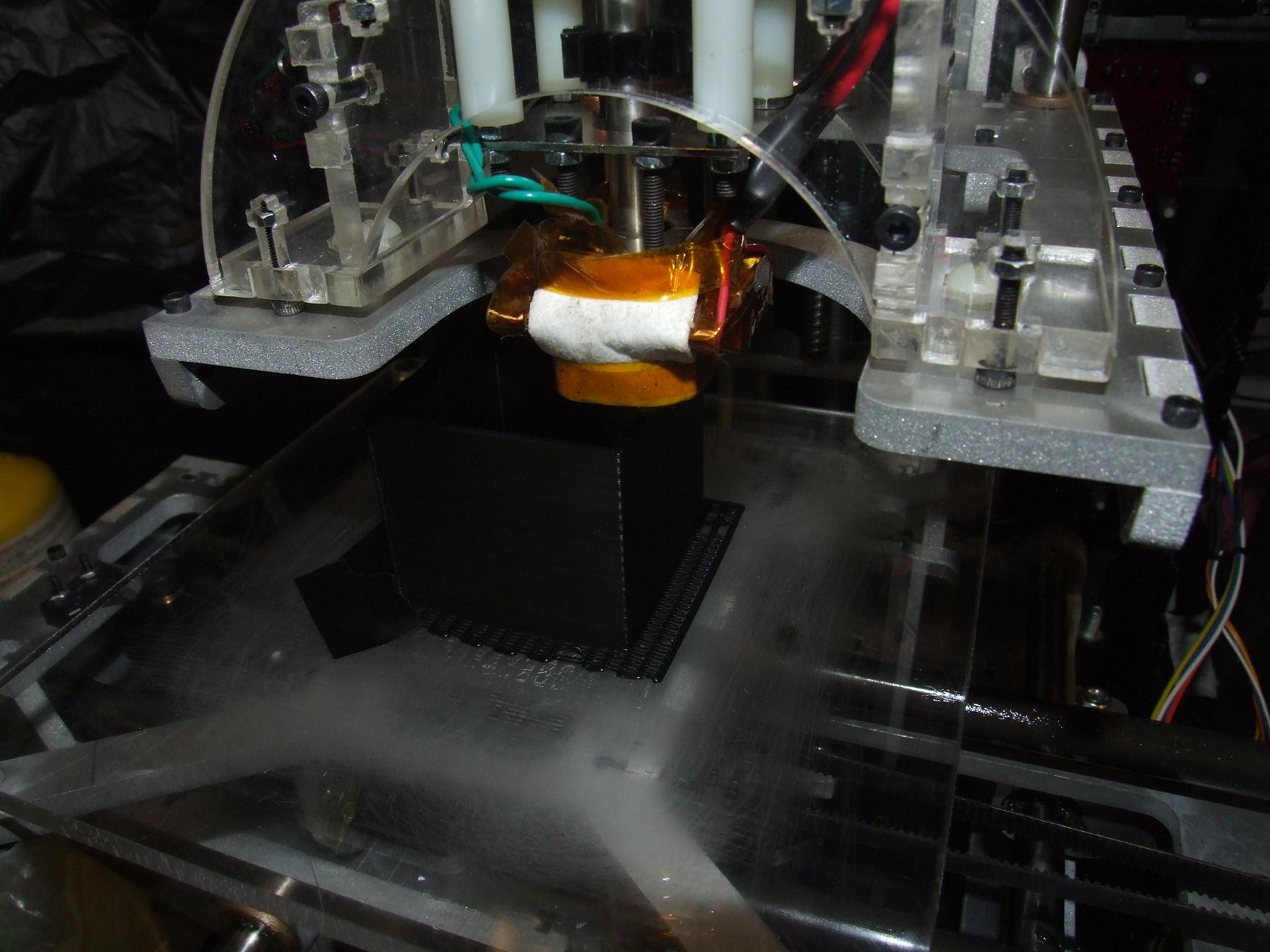
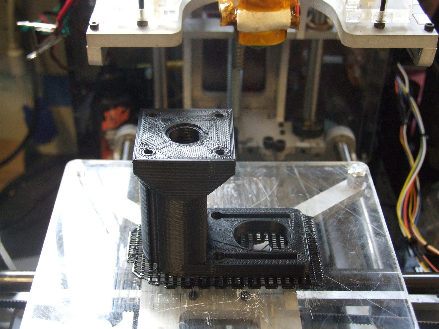
At last, the trippy PCB heaters!

Trriiiippy.

I made one change from the version I keep linking to – there’s a center hole in the board so I can wedge a thermistor between it and the aluminum heat spreader. You know, so I can actually find out the temperature of the working surface. Otherwise, the trace resistance checks out (the squiggles on the bottom side in the design were put there in case they did not…) I’ll need to cut a single square of aluminum for the heat spreader. The aluminum will then be thermal-epoxied (not bolted or sandwiched) to the top of the board.

I got two boards, but will only prepare one of them for now.

segfault

Poor Segfault.

No, I haven’t completely trashed it yet again. It’s been working, but always became weak after 30 minutes or so because all I had in it were two of Überclocker’s packs. It would usually just fall over after an hour. So after the term ended, I swore I would make a new battery just for it such that I can reliably bring it out for demos. Naturally, with the ennui of the break, I felt unmotivated to do anything. Additionally, during an unfortunate scooter-organizing incident, the cable leading to the control knobs was sheared off, so it was just one more impediment and grunt-work repair job I had to tackle before it could even work again.

So maybe I did completely trash it. Either way, I guess it counts as New Year’s resolution to repair Segfault? I’m not sure.

Here’s where it starts.

Ah, another brick of A123 26650 lithium nanophosphate cells; here, being prepared and tinned.

Segfault’s completely empty right side was just begging for a brutally large battery. I measured everything out and found that I could easily fit a 5 x 7 cell array. Since Segfault already demonstrated operation on 7S (about 23 volts), I’d have to make a pack that had 5 cells in parallel. This is more or less a 146% \m/etalpaKkK. With 5 2.2 amp-hour cells in parallel, the total watthours count of this pack comes out to be around 250. It ought to be enough to keep Segfault running for two hours or more.

The enormous \m/etalbraid makes a return on this pack. Grounding braid is now my staple “battery bar”, as shown by the \m/etalpaxXx themselves and RazEr rEVolution’s pack (and the Clockerpacks, and the monstrosity I made for Cold Arbor). Segfault will never draw enough current to overload these busbars, but hey – maybe one day this thing will be repurposed. Have to plan ahead, you know.

Soldering is discouraged on cells like this because of the risk of melting the polymer separator close to the terminal, which results in bad. If you’re very fast and have a soldering iron with a large tip (high thermal mass, effective thermal bath), it’s definitely possible. I stuck to my 3-second rule here – once the joint starts melting, I count 3 seconds to smash it down and add more solder. Once that time is up, I immediately move on to another cell, and don’t return to that one until I’ve visited the rest of the pack.

It’s probably not very legit, but I haven’t overheated a cell yet…

After the whole pack got busbraided, it was time to add the wires. There’s three heavy-gauge wire pairs coming out of the pack this time. The two off to the right interface with the existing double battery connector in Segfault. There’s no reason to have a double connector in the thing, but it’s the way I originally made it to accept the robot batteries.

The single cable to the left is only used for charging. But I guess it could be a third discharge port if needed.

I ordered JST-XH connectors in several different sizes from Digi-key, so I was actually able to make a legitimate balancing harness.

Now the fun part begins: Packaging the whole thing.

MAGIC!!!!

So there’s no soda bottle big enough in this world (please prove me wrong) to swallow up 5 cell wide rows. The \m/etalpaxXx required a 3-liter soda bottle, and they were only 4-parallel groups. And while I could have planned ahead and ordered wide heatshrink tubing, that just doesn’t work with how I like to build these things – i.e. right now.

I did, however, buy a six inch wide roll of Kapton (Crapton, since it was from a Chinese ebay seller, and doubtlessly not real DuPont polyimide film) for Make-A-Bot’s future build surface. So I decided to just give it a try with finishing the packs up. With some cut up sheets of adhesive-backed foam rubber fitted on the cells for shock isolation, I wrapped the Giant Crapton around the whole pack several times in two separate loops. I think it came out great. The tape doesn’t really stretch, so it doesn’t look as “heat-shrinky”, and I wouldn’t say it’s waterproof. But it got the job done.

After a brief interlude to reconnect six little wires, Segfault is now once again attempting to kill innocent riders.

The Makings of the Make-A-Bot’s Mak… Damn it all.

You might notice that I’ve been missing for about a week after having produced nothing of substance for even longer.

I’ll be honest. I’ve been spending the time staring emptily at Make-A-Bot while it cyclically exudes a little molten filament of plastic and waves it around. Watching this thing work is disturbingly addictive, and I wouldn’t be surprised if I’ve already been hypnotized and brainwashed into building clones and replicators. That, and the end-of-year institute shutdowns coupled with the recent eastern seaboard blizzard meant that I didn’t have much else to do, or new parts for Manbeargryllspigtankmelonsharkweek to ogle over.

Maybe I should just get it over with and print myself a chin rest.

Anyways, the past while has been filled with more experimentation and silly prints. I’ve also started down the neverending path of making upgrades to your 3d printer by 3d printing them. Here’s a selection of some things made on Make-A-Bot recently.

MaB has been having issues holding Z-axis tolerances for whatever reason. All my parts would seem to come out a millimeter or two taller than they should be. I couldn’t tell if it was ratiometric (which would entail fiddling with the steps-per-mm parameter in the machine definition file) or just random. One attempt to find out was making this 50mm tall (by design) piece. It was also a good test of the thin wall ability of the machine.

It ended up around 52 millimeters tall, which told me that somewhere along the line an extra millimeter or so is getting added. I’ve had 20mm prints come out around 21, and 10mm prints come out around 11. It’s definitely not ratiometric.

So what the hell is it!?

Oh well.

One of the cool things about 3d printing is the ability to make silly sculptures at will. Here’s a hamster. This was done using 0.25mm layers at 60mm/s speed. I was surprised the thing could move that fast.

There was plenty of overhanging areas for the line to sag, but it seemed to handle those well. The ears, however, were a bit troublesome because I didn’t have a Minimum Time per Layer parameter set. They couldn’t cool fast enough before another layer was paved over, so the ears ended up a bit droopy. Setting a MTPL would make the nozzle hover around the part for a while before continuing.

Between the ears is more Undamped Drooling, something that I hope to fix soon.

And here’s a.

No, I can’t see how everything can go horribly wrong at all.

This print was a “high aspect ratio” piece done at 55mm/s and 0.3 mm per layer, and it came out great. I was afraid that the shaking of the platform when printing small profiles at the top would cause bad surface finish – and it does show a little. Otherwise, same problem as the ears of the hamster – small profiles didn’t get the chance to cool off.

The model is called the Pink Panther Woman.

Something which aided first-layer sticking performance some was parking a space heater right next to the machine. It kind of simulates a closed-cabinet heating system by keeping the build surface and atmosphere immediately around it nice and toasty. This was just a random hack to help some of the larger prints stick, such as…

This stepper motor mount for the extruder. I’ve been aiming to switch to a stepper-based extruder for better control of the flow rate. Stepper extruders are also one of the best solutions to Undamped Drooling since they can predictably and quickly cycle back after an extrusion run in order to “depressurize” the filament.

The part itself is a quick rework of this thing, with the “control tower” elongated to fit my bigger steppers. Unfortunately, as I discovered, the extruder control driver chips are not current limited. That means they can realistically use a stepper with 10-20 ohms resistance…. not my crazy 0.8 and 1.4 ohm ones. The driver chips entered over-temperature shutdown about as fast as I could turn my attention from the control software. I’ll need to locate 10-20 ohm steppers before continuing.

Print parameters for the part was the old-but-good 40mm per second at 0.4mm per layer. This one seems to give the best and most consistent surface finish at the end – the faster 0.3mm setting I settle on only seems to give good finish on smaller parts, whereas larger parts would see some filament not quite being packed down on the layer below.

After getting tired of looking at flat black things, I decided to pull out the roll of PLA I also bought. PLA is a clear (when injection molded or properly extruded) material that makes LED-worthy prints. As I found out, it’s also tenacious on plain acrylic (do not use a raft… it does not end well) and also exhibits great extrusion characteristics. It sticks well to itself, and when extruded very near its melting point, it cools almost immediately upon exiting the nozzle and so parts with overhang seem to build better. Oh, yeah, it actually does melt instead of turn goopy like ABS.

The down side of legitimately melting is that it does store more heat for longer than the ABS. This was noticed later on parts which had small, quickly-printed profiles which began sagging. The solution ended up being just activating the minimum time per layer option.

But for now, I used the stock included PLA settings on another version of the hamster. It turned out pretty well, but not what I’d call transparent. Or even really translucent.

I decided to use shot glasses as calibration objects this time. I figure they are more usable than small cubes of varying sizes…

The “Cool” tab in Skeinforge (where the minimum time per layer option is found) also lets  you add a ventilation fan to the extruder. I found a 120mm case fan and tossed it on the extruder controller’s spare output. The “Cool” options then turns on and off the fan during the time the nozzle spends hanging out waiting for the minimum time to pass. On the rims of the shot glasses, this helped immensely.

I later discovered that turning the fan around (such that it pulls air upward after it flows past the part) is a much less harsh thermal cycle and resulted in better clarity for the PLA while still letting it maintain structural integrity.

The calibration cups were used to test different temperatures and feed rates. There appears to be several schools of thought on how to extrude PLA – one of them says keep the temperature at or near the melting point (about 200 to 210 deg. C), and another says just beast it all and crank the temperature way up to 240 degrees.

Well, they all seem to work fundamentally, but one of those is definitely not waterproof. Though it’s leaking out of the seam along the side, not the base.

“C” and “No C” refer to whether or not I had the cooling cycle enabled.  Emptying the glasses (don’t worry, they were full of Mountain Dew) better shows the effects of the different settings:

What I’m observing so far is that the hotter you let PLA sit as it prints, the more optical clarity you get between layers. Make sense, since one layer mushes into the next better. However, you also lose structural integrity. The “No C” print exhibits this clearly – it’s almost transparent in some places, but very inconsistently so. The angle makes it look good, too. It actually has many deformed strands and sagging perimeter threads coming off it, and flexed during print like nobody’s business.

The very first glass is at the left. This was before I added the fan to the cooling cycle, so I indicated it with just “pause”. It demonstrates better clarity than the actively-cooled one (215/45/C) at the right, which had the fan going the whole time.

The best one, though, was the 240 degree print. The fan seemed to bring the body of the cup down to barely below its softening region before the head started on the next layer. It demonstrates a more consistent translucency than the other prints, which I find more pleasing than splotches of clear. Not as absolutely transparent as the first print, but the first print took forever since the wait cycles had to be so long.  With the fan’s help, the last print finished in a little under 40 minutes. The “M” in the logo is also less deformed.

For now, it seems I’m a member of the just beast it school of PLA extrusion philosophy.

Lastly, I tried another high-aspect-ratio print using the cooling cycle enabled process. The Undamped Drooling on this one was almost disgusting since the “tower” was so narrow that it spent more time waiting than printing. I tried taking care of it with a torch – it kind of worked, I guess.

This was done at the prescribed 240 celsius, 45mm per second setting. The layer height is set to 0.35 millimeters to compensate for the increased speed.

So that’s all for now. Eventually, some day, after I finally get my trippy heater board I’ll try printing larger things in ABS. I’m interested in the combination of heated build surface and cooling ventilation for sure.

I’m also legitimately considering renaming Make-A-Bot to something that doesn’t sound exactly like Makerbot. It was great as a project development name, but I’m starting to run into issues answering questions about it, and explaining to anyone else where to get their own. It’s just more explanation than I foresee myself doing without being snarky.

Any suggestions!?