Poor Tinycopter

Based solely on that title, you can probably guess that no it’s not working yet. Tinycopter has been reduced to a case like all of my controls projects: in software limbo. Unlike mechanical things, which either work or don’t, debugging software requires me to be a bit more methodical. It’s definitely almost there though!

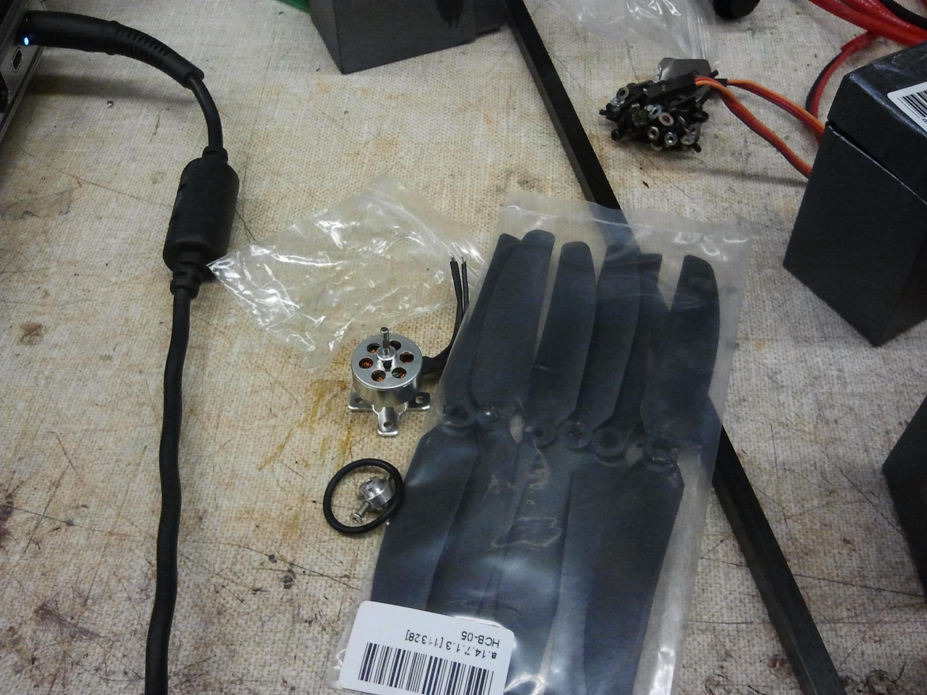
To get Tinycopter flying before my Hobbyking order for small ESCs arrived, I decided to chop and repackage some larger controllers. They’re the 18A Turnigy Plush common on medium sized copters.

They weigh about 20 grams or so with heavy 16ga wiring, the thick shrink wrap, and the aluminum heat spreader plate. Because I was going to use them for all of 3 amps or so, all of this was chopped.

With 20 gauge wires, thin shrink, no heat spreader, and a shortened servo cable, I got the boards down to 12 grams, which was good enough for now!

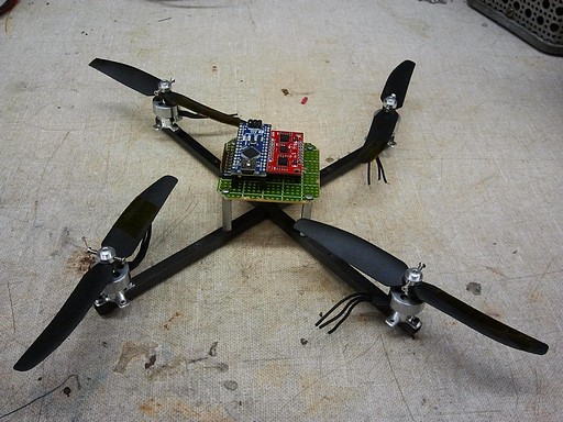
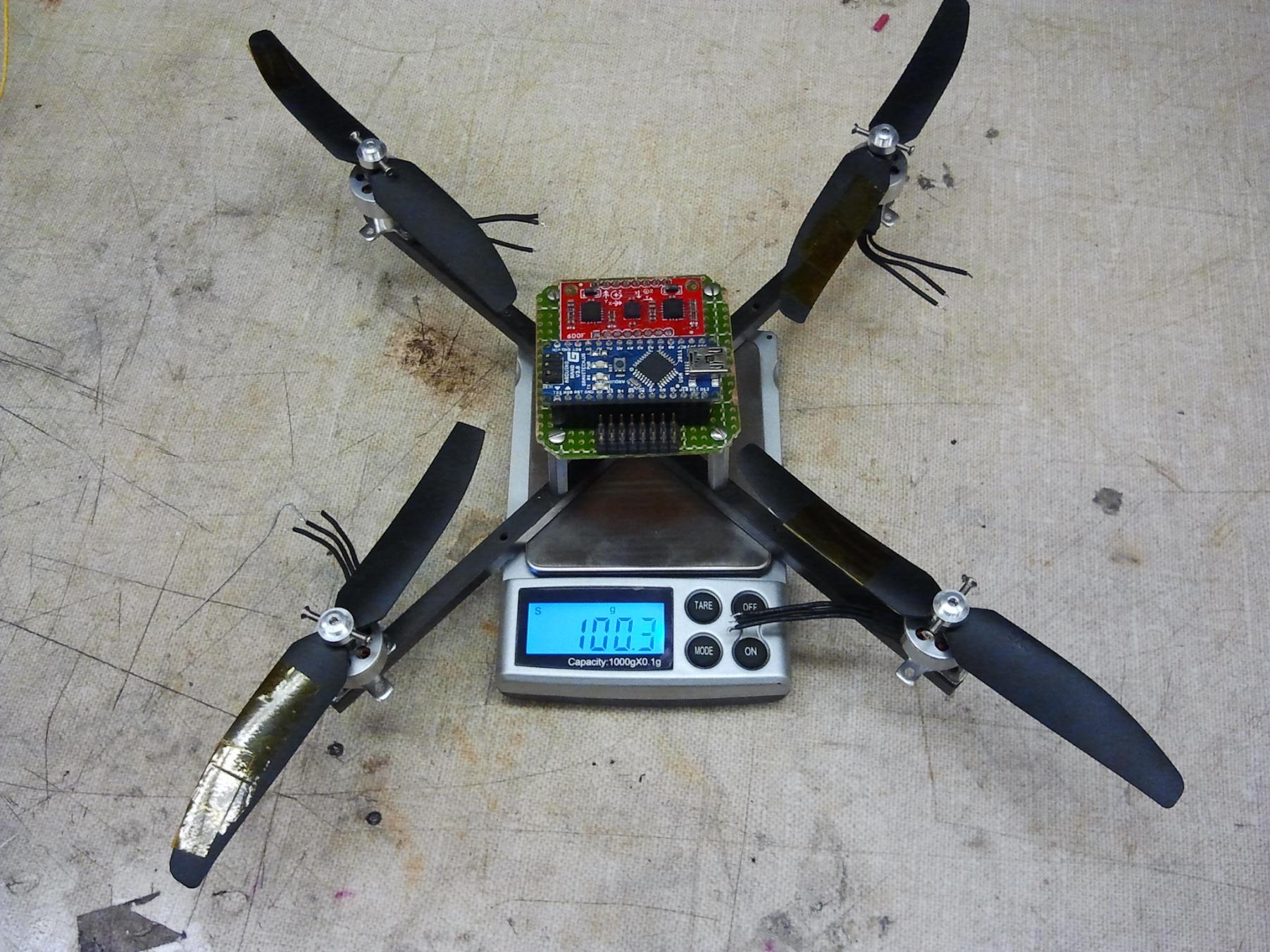
Given that the ESCs are roughly half the starting weight, I piled 2 of the stock ones onto Tinycopter to get an idea for final weight. It looks right on target – 200 or so grams with a massively oversized battery. Once the 370mAh ones arrive, it should be around 175-180 grams.

With everything fitted out, I took off the props first and began constructing the stability controller. I compartmentalized as much as I could and tested as I went along making sure every stage of the code was functioning. This pretty much took a whole day. Unlike Edgertoncopter, it wasn’t banged out quickly with inline functions and shady loop timing.

But Edgertoncopter works, and unlike Edgertoncopter, Tinycopter didn’t.

The result of the first free flight was immediate instability and explosion:

Well, at least it wasn’t as bad as the last instability resulting in explosion.

D’oh.

After a whole evening of prop changing, loop tuning, and optimization, Tinycopter is pretty well scarred.

And it still doesn’t fly stably – it enters a slow but increasingly divergent oscillation, almost as if something is lagging or being too slow in responding. This resulted in a few hours of tearing my hair out trying different gains.

But I know exactly why now, and I’m going to fix it first thing tomorrow. This time, I actually did the software correctly, and the real problem is far worse.

the real result of this experiment

Here, have a look at its version 1 sketch. Note that this will not fly anything yet – there are some fundamental issues in the code, but…

The real result of this whole build is that Tinycopter does not use XBypass.

As quickly as I threw together that hack, it was superceded. Tinycopter uses, instead, the pin change interrupt and timing method first outlined in the XBypass post, but augmented by commenter beak90’s code contribution. I implemented the PinChangeInt library version 1.3, and am glad to say it works extremely well. The resolution given by the built-in timer (micros()) is 4 microseconds, which is reasonable for controlling things, giving approx. 250 discrete steps in the R/C servo pulse width band.

I will probably recommend this method over pulseIn() for all but the most basic servo reads. It’s easy to set up, does not require caressing the ATmega328 manual, and works great.

The overhead introduced by my code and the PinChangeInt’s natural overhead seems to be around 25 to 30 microseconds, which… honestly, taking a 60us chunk  (one falling and one rising edge for subsequent channels) out of the code periodically every 1000 to 2000 is much, much better than several tens of thousands. My control loop code seems to complete in about 900uS – I set a pin high when it starts and low again when it falls, and it forms a neat almost-50% square wave at 500Hz. It takes a while because of the dozen or so floating point operations it has to shove through.


Revenge of the Quadrotor

I knew I couldn’t leave it for long.

Born of the wreckage of the Deathcopter, kind of like a carbon fiber and superglue phoenix which is not on fire (yet), is a brand new quadrotor! Introducing tinycopter:

It’s 99% less likely to kill me! Yay!

I pitched this frame together in a little under 4 hours with borrowed 4pcb parts and absolutely no planning beforehand. That means it should work perfectly when I wire everything up.

I began the process of scrapping the big frame after determining that using the two battery struts, which are square, would let me build a pretty sturdy combination motor mount and frame. I have still yet to test the two remaining fans – should they prove to be structural, maybe I’ll build something silly and fan powered again (or maybe an Avatar Gunship or something).

The IMU and Arduino Nano were recovered from the 2.007 carrier (which will see service in another vehicle some day) for Tinycopter.

From the mass of quadrotor parts Shane purchased, I’m going to use the Hobbyking 10 gram motors and 5×3 propset (which were too big for 4PCB). Conveniently the 10g motors also have a cross shaped flange base, of which I will use two of the mounting holes.

I drew up a quick Solidworks sketch of where the mounting holes should be, and then made both struts in series using the mill’s X axis for positioning.

There is a “log cabin” joint (I am completely not sure of what the actual name of this is) in the middle of the carbon fiber rod that I just milled in the same setup. This allows the “X” to have a contiguous flush surface, so I don’t have to make any strangely shaped adapters in the middle. The four sets of holes near the center are for mounting electronics and accessories.

The joint is very tight-fitting, so I wicked some ultra-thin CA into it to keep the struts together.

All together!

I spent a few minutes investigating different ways to assemble the 10 gram motors and props. While it comes with a prop saver type hub, it is terrible.

Okay, so the hub itself is pretty okay. The props, however, are garbage. Not only are they totally off balance (kapton tape is visible on them to correct for the imbalance – the worst one needs almost an entire leading edge full of them!), but the hubs are not level – they have sprue bits hanging off them requiring a bit of knifework, and the bore on the correct side of the prop to use with the prop saver is very loose and sloppy. The rubber band that forms the prop saver mechanism is also fairly loose, and I’m not keen on it flying off.

So I turned the whole thing upside down and used the prop saver ring to sandwich the prop against the motor face. Nothing’s being saved any more, but it’s way more solid.

Title image again! I quickly whipped up an electronics mount out of some perfboard. 1″ tall 2-56 standoffs, actually 4pcb’s spare landing gear, make up the electronics mount. The standoffs are flexy-CA-glued to the carbon fiber, since I could not get 2-56 threads to hold in the material. The electronics board will be very simple – just the Nano, the 6 axis Razor IMU, and some headers.  5 volt logic power will be supplied by the motor controllers directly.

I currently do not have a matched set of 4 tiny motor controllers, but they should exist (either found or shipped) by the end of the week. I’m planning on using some 6 or 9 gram controllers from either Hobbyking or equivalents from HobbyPartz, but that’s all contingent if some can be excavated on campus.

The battery will be a 2S or 3S, 480 or 500mAh pack. I was testing with a 3S pack and the motors seemed not to mind, but they produced far more thrust than I feel like was warranted – 100 grams or more per motor. However, I’d have to order 2S packs, since I don’t have any.  The plan is to have the battery, which is the heaviest single part, reside under the electronics deck. This keeps the center of gravity fairly high, and it should almost be inline with the props.

This is fully intentional: Intuition and urban legend both suggest that having a low center of gravity (defined as below the vertical center of thrust of the props) results in a more stable vehicle due to the pendulum effect. This is, however, actually not the case. The pendulum effect actually contributes more strongly to unstable oscillation the lower the center of gravity is. Ideally, the CG should be exactly in plane with the props such that inertial forces do not have a moment arm to affect the system, but this is practically difficult to achieve. In that case, it’s actually better to have it a little high, above the props.

Weird, huh? [1]

Tinycopter is going to be a bit chunky, since I still can’t grasp the idea that flying things need to be light. Without controllers, battery, receiver, or wiring, it weighs in at 100 grams. The battery should be about 50 grams, the controllers around 30 grams, and the receiver about 9 grams. So, the all-up weight of Tinycopter should be about 200g. I’m sure the battery can get smaller if I go ahead and order some packs (360mAh, 7.4v packs are usually around 30 grams).

Despite me just having sung its praise in the last post, XBypass will not be used on Tinycopter at first. Commenter beak90 has pointed me to the PinChangeInt library in Arduino, so I am going to try first to do that thing I described in the XBypass post with timers and pin change monitoring but without the ass of real software. This means Tinycopter will use a stock radio.

The electronics in Tinycopter have been positioned to use the “box” orientation, which I find a little more intuitive since I can think about it as some kind of flying robot. I’m used to driving robots on the ground, and my transmitter technique is definitely reflective of that. I should be able to make it ‘mode switch’ in software as needed.

Additionally,

No external t-nutting or support equipment yet, but it’s getting there.