What happens when something I build doesn’t work? Generally, I go back and rebuild it. It might take a while, part of the time being spent recovering from the emotional scarring and psychological trauma that comes with things not working. In the case of the major vehicle projects LOLrioKart and Segfault, it took several tries and the better part of a year. But what’s nice about 3d printing is that you can just whip out another iteration pretty much on demand – at least when you’re not running desperately low on material. Come on, Makerbot, restock your big ABS and PLA reels!!
This whole Chuckranoplan thing only started like… last week. As soon as I realized that μ-Chuckranoplan 0001 wasn’t going to work out, I started designing the next version, so to speak. By “designing”, I really mean staring at more pictures of delta-wing craft on Google Images and wondering (besides why the hell they look so derpy) what they have in common. Tangentially related, Chuckranoplan now has its own page, and several other parts of the site have been updated also.
Here’s the designing and (now in process) build of mCRP 0002.

And we begin. This version started out much like the last, except now I had a much better grasp of what the Loft feature does. I was also directed to a database of downloadable airfoil content, so I could even use a REAL AIRFOIL! this time. For the new main wing, I selected the Clark YH section for its flat bottom with mild reflex, and for the tailplane (still unmodeled above), I stuck with a cambered NACA 6412. The issue is that the airfoils there are still not parametric, so I was stuck with hitting the Scale button to get the chords I needed. That’s fine – once I have a need to actually tune the airfoil to my liking, I don’t think I’ll be using a premade database of them.
I decided to ditch the 3d printed vertical stabilizer tail and instead go for a triangular loop of sorts with the verticals made of carbon fiber rods to save weight, since this is probably going to weigh 8,000 pounds as well. The CF rods will be wrapped in something light and filmy to replace the former vertical stabilizer section.

Alright, we’re getting somewhere now. It’s starting to look like some kind of strange alien bug with four eyes.
The nose was more “scientifically designed” this time, and by that I mean I actually had a fixed order of operations that resulted in something vaguely hydrodymanic, instead of “Loft, loft, fillet, cut, fillet, loft….” until it looked like what I would have drawn in 3rd grade.
The wings actually wrap around the body completely this time, in accordance with Youtube videos and pages with low-resolution pictures from the late 1990s. The fuselage blends into the wing on the bottom, and the attachment is just done with a flat feature in the cross section of the wing root.

Now I’ve added the canopy bubble and mounts for the eventual More Pylons that I Must Build. Notice the little ears next to the bubble – they are actually screw attachment points, and there is one more on the bottom. The body is designed already as a thin shell, and the nose portion can detach cleanly so I can actually stuff in electronics. The tailplane has also been modeled here.

If you’re wondering why the 30mm fans don’t suddenly look derpy any more, that’s because this model is bigger. Way bigger. The total wing area will be effectively 5 times or so of m-CRP 0001.

I had to remember alot of my coordinate transformations to model the tailplane, because it involved pivoting a reference plane at 60 degrees off of a line drawn on the XY plane at 45 degrees to the X axis, then drawing a line offset by 33.01 degrees from that 60 degree rotated plane. Or something – maybe not in that order. This is so the CF rod holes in the tail are directly in line with the ones in the body. The fat extrusions at the end provide the anchoring point for the tail rods.
I’ve also added the model CF pylons, but haven’t designed the little adaptors that will mount the fans, since they still haven’t arrive yet.

m-CRP 0002 in profile. While the fans haven’t been rotated to match, notice that the pylons are actually canted downwards towards the body by about 5 degrees to act as PAR.
oh hey, fans bus motors!!!
I finally got the shipment in. Here’s the AEORC EDF-30 system that Hobbyking sells. They’re SO CUTE. Like little ducted kittens.

And to my utter surprise, my guesstimated dimensions were spot on. At least in the important part – the outer diameter of the case.
Along with the stock fans, I got a sampling of other small Turnigy inrunners (10 and 12mm) and some GWS 30mm mini-EDF parts. They will be used if two bus motors prove inadequate.
While the product has a ton of negative reviews on HK, mine seemed to be fine and balanced running on 7.4 volts. On 11.1 volts, I estimated that the thrust was greater than 3 ounces, but one started to smell slightly funny after 5 or 6 seconds. So it looks like m-CRP 0002 might be running 7.4 volts to save weight and to prevent me from Beasting It.
printing
I made a key modification to MaB before starting this build. Previously, I had a 125mm case fan just kind of chilling on top, pulling air upwards past the part. The problem is this really only worked when the part was very flat, so the fan was forced to draw air past the platform surface. Once the part got tall, the fan could get air from anywhere.

I popped into MaB’s design model, positioned the geometry of a 80mm case fan, and using my newly acquired lifting skills, designed this ventilation duct that parks directly under the extruder motor. It holds itself in place by virtue of enveloping some of the cap screw heads on the platform surface. A dab of glue to secure the fan, and I was in business. Now the fan blows down, impinging upon the top layers of the part and spreading along the platform. The 80mm LED fan is much weaker than the 125mm server fan I used before, so I just instruct the machine to always keep it on.
This resulted in a much more predictable dimensional variation for the builds.

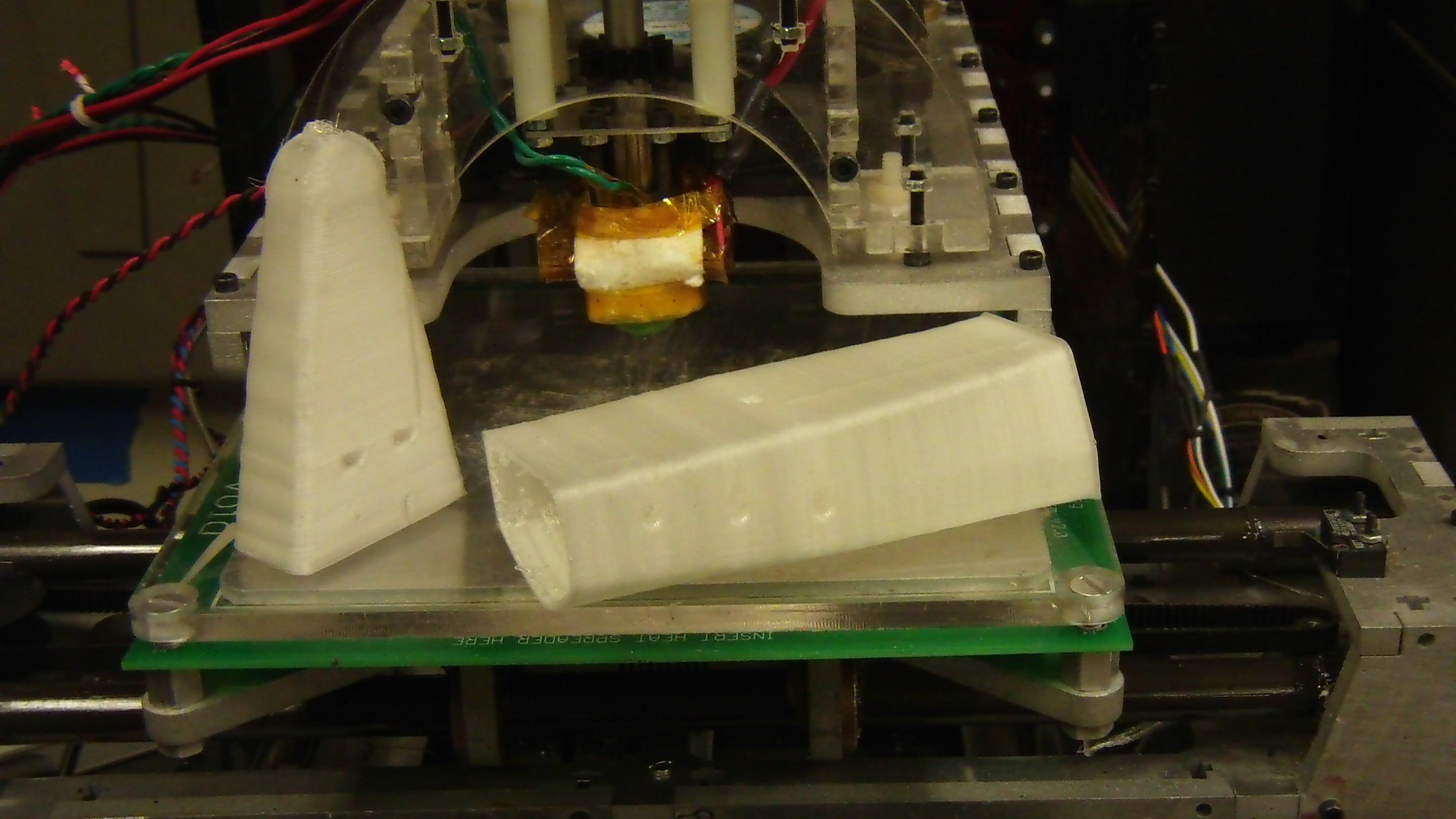
Here’s the three body sections after the print run. The fan helped greatly on the small profiles of the nose and tip of the tail. I split the main body into two pieces – one of which is my artificial shell hull, and the other one is nominally “solid” but is just a 2-walled shell with zero infill. The single piece body would have been too tall to safely print, despite MaB having the Z-axis travel needed.
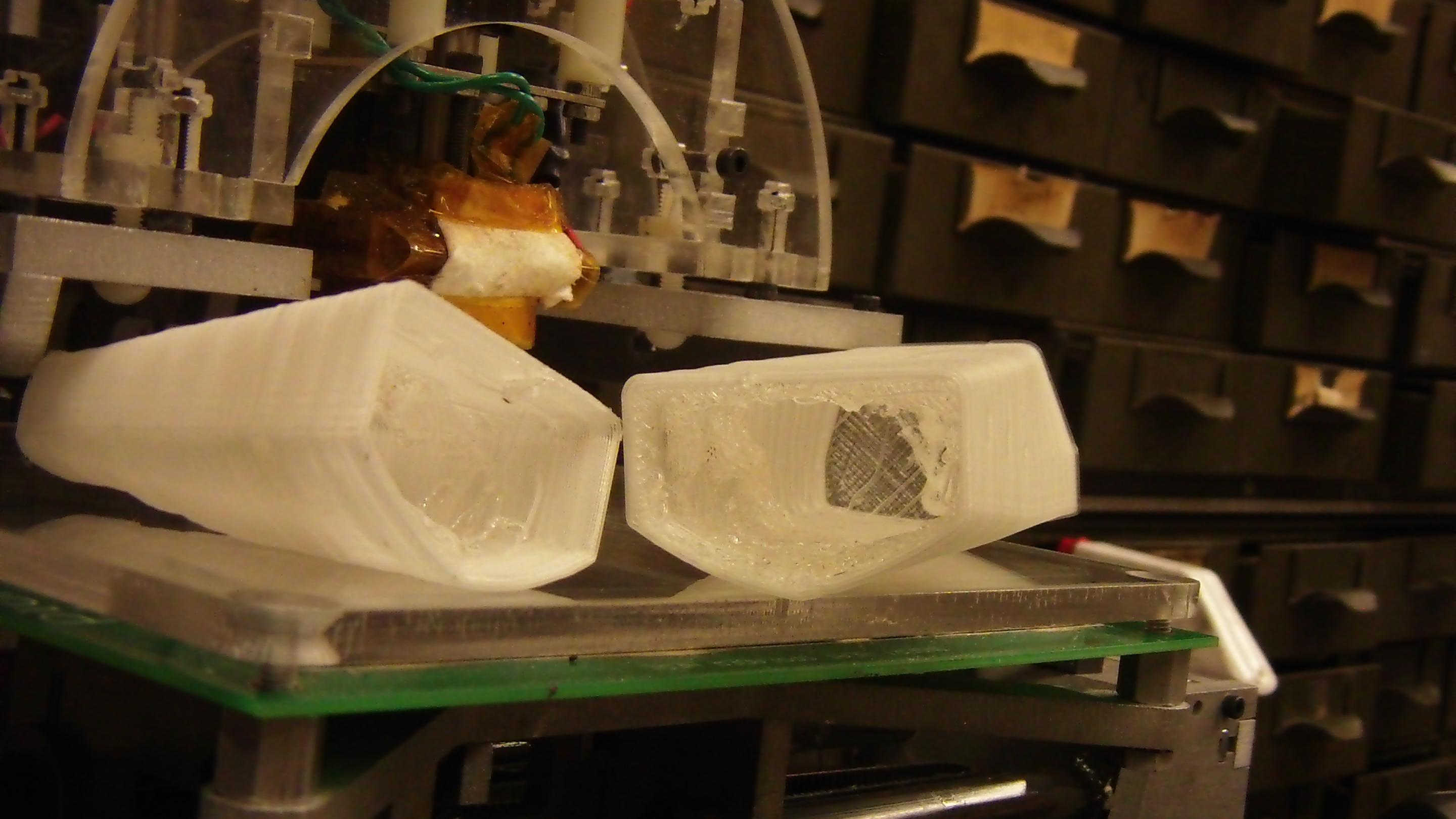
The addition of the cooling fan brings out an interesting feature of the print – namely, the thermal variations of the extruder. Check out the horizontal striations on the parts. Initially, I thought it was an artifact of the Z axis leadscrew because of my irregular machining. Further investigation proved that it was in fact the temperature of the extruder fluctuating in the hysteresis band around my nominal extrusion temperature.
I’m not too concerned, but I do wonder what can be done to minimize variations – I can think of a few things, such as less thermal mass of the extruder, higher power heater for the overhead, better coupling between thermistor and heater core, and maybe changing up some control gains or making the control nonlinear. This is something to explore for the next iteration.

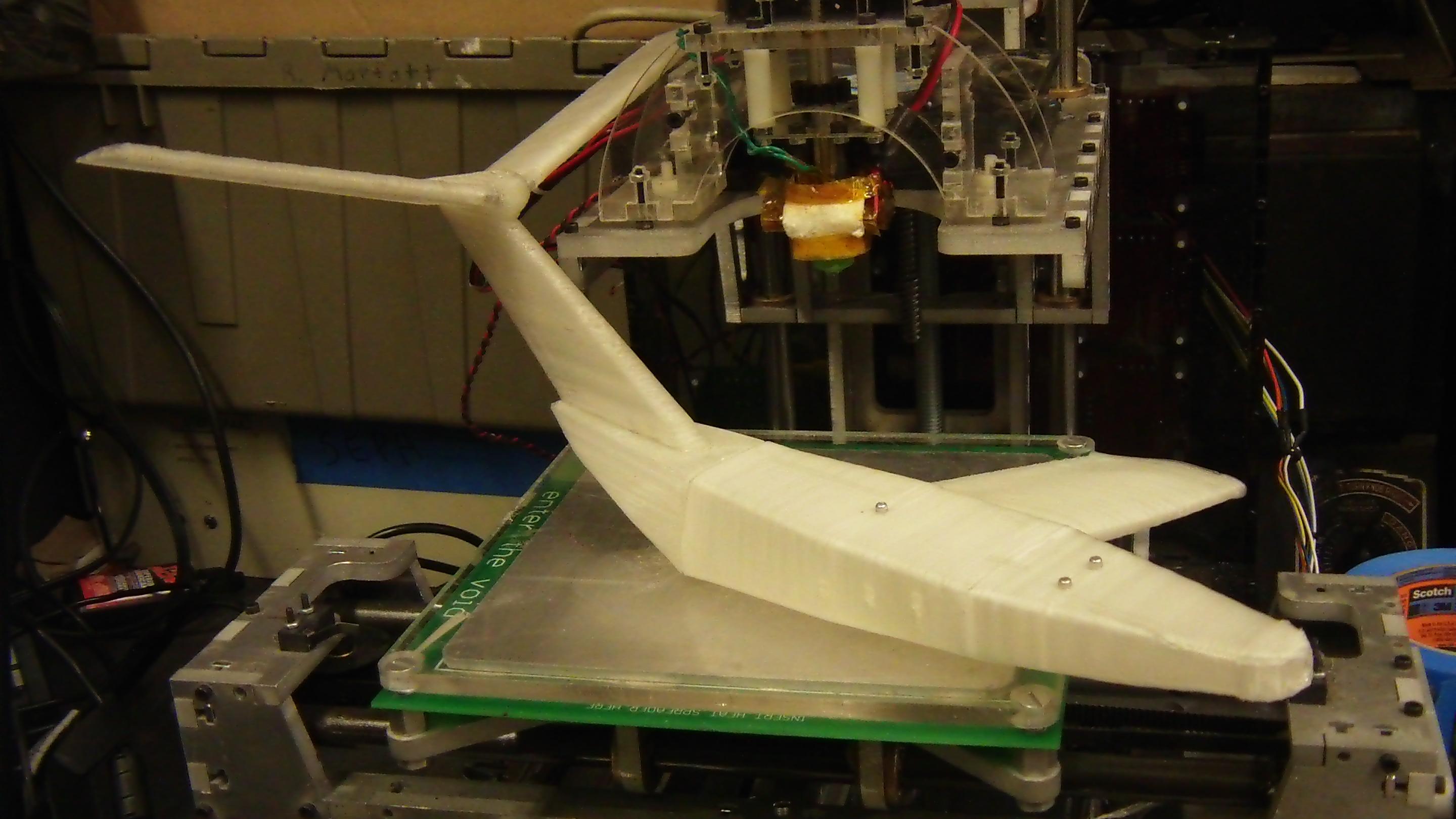
And now for the big guy This is one wing (I forget which…) in progress. Notice that both ends have curled up slightly – that just because this thing is so big that printing in anything but a closed and heated cabinet is essentially asking for massive thermal stresses with the associated strain.
I actually resorted to supergluing the ends of the first layer down using ultra-thin Loctite 420, which wicked into the gaps left by the plastic threads. Even this lost out a few times to the power of curling plastic. Eventually, I found the amount of superglue which would hold the wing flat as it finished. It’s an absolutely disturbing amount.
Number 2 on feature request lis for next 3d printert: Heated cabinet.
That’s all for now. With both wings and the main body printed, it’s time to get started on the even-more-ginormous tailplane (as well as wait for my carbon fiber rods…)