IT DOES THE THING
What’s the thing? Well, I don’t know, but IT DOES SOMETHING.
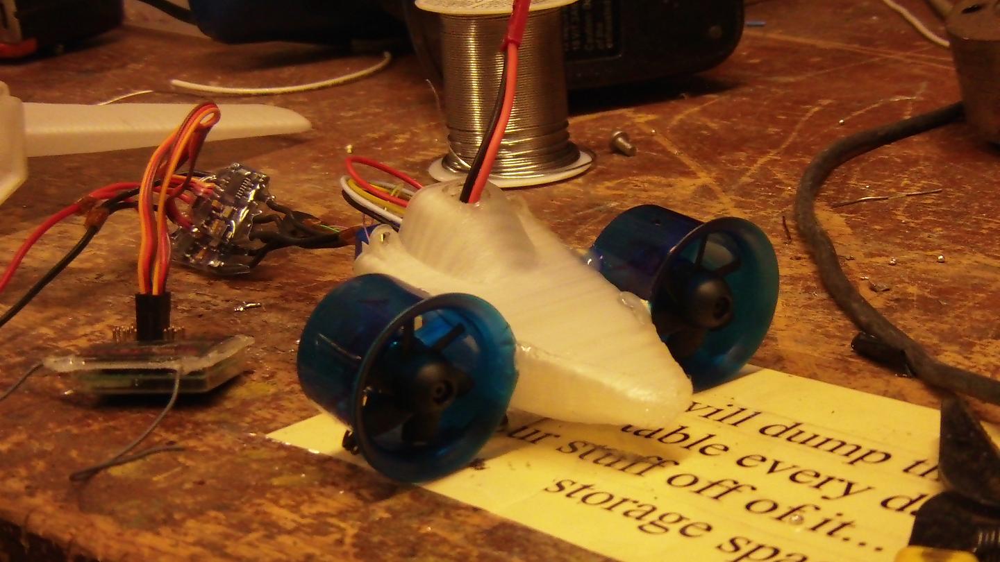
As a reminder, here’s a picture of Chuckranoplan 0003.

It’s impossible to see in this picture, but I’ve very carefully designed it as a hollow shell with 0.5mm walls and 1mm thick internal ribs. I played around with the hollowness in order to try and trick MaB into making each cross section a single path, so there’s no jumps or hops for it to leave ugly gaps everywhere.
I used a variation on the incomplete hole such that the routing script Skeinforge was forced to follow a 0.5mm wide path around the perimeter, then forced to go back and forth across a 1mm wide internal rib that actually dead ended 0.1mm short of completing an internal compartment. If this wasn’t done, MaB would try to jump across the part and make closed loops, but the extruder doesn’t start and stop that quickly, so earlier test prints got nasty gaps and chunks missing. The 0.1mm gap means physically the ribs still join the outer surfaces, but the software thinks they do not join.

Using this technique, I was able to produce this one-wall-thick Chuckranoplan 0003 hull. It weighs under 1 ounce, and in fact does float.
Okay, so it’s actually four chunks. Single wall parts like this deform and split much quicker than multiwall parts, since their structural integrity is so poor. Now that I’ve learned how to dupe the printer, I’ll probably begin adding internal ribbing to prevent splitting and the buckling that is clearly visible.

A few hours later and I’ve managed to pop off the wings too. These things are the second largest objects MaB has ever printed – the first largest being the wings of 0002. These wings are shorter, but the chord is the same. There was some base warpage, but this time, they’re at the outside pontoons, which means I really have no fucks to give.
Notice the splits and cracks at the trailing edge, as well as… well, all over the place! The heat-cool cycle is really rough on the single wall plastic. A heated cabinet would have prevented alot of these stress cracks from forming.
The gaps were patched up with Goop cement, which was also used to join the wings to the body.

Next, a propeller.
Alright, just kidding. These are actually the three parts of the tail airfoil, arranged in a pretty flower shape so they could be printed off all at once.

The tail suffered some splittage issues too, but they were repaired with superglue and… more Goop. By the time I’m done, this thing is going to be half Goop.
To assemble the tail, I cleaned up the 1/8″ through-holes using a hot stick of steel to melt-form the ABS plastic. The print process doesn’t leave perfect holes, so this was a way to make sure the carbon fiber rods didn’t get stuck or were … denied entry or something.

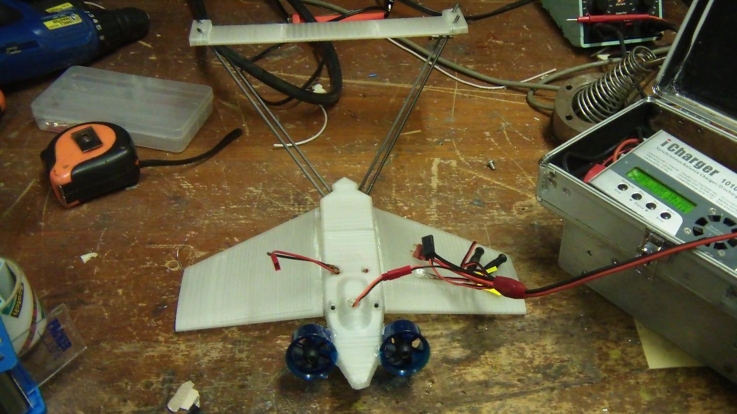
Alright, here’s take number 1 of Chuckranoplan 0003. This is probably the biggest thing MaB has ever spit out… and now that I’ve figured out how to make these things for realsies, they’re gonna get even bigger.

Okay, here’s take two.
omg what happened to the tail?????
Well, if you observe the previous picture, you’d notice that the tailplane isn’t in a lifting configuration at all. In fact, it’s at about -3 degrees from horizontal or so. This was due to my inattention when supergluing the tail rods together. So what do I do now that I need to change the angle of some superglued CF rods? Well, I have to break them apart and add in spacers.
The crunching sound of the tin shears was rather sickening, like re-breaking an improperly set bone.
Unfortunately, I couldn’t quite control how much spacer I added, and the tail ended up this time at like 30 degrees. I think it’s legitimately making more drag than lift.
The method of joining was gobs of superglue with a heatshrink exterior, then wrapping the entire thing in blue masking tape because blue masking tape.

I added some cute trailing edge flaps with… more blue masking tape. Hey, if you look at it from afar, it looks like I actually meant for them to be blue.
The machine nuts up front are center of gravity adjusters to bring the CG away from the back of the wing. Unfortunately they also added another ounce.
It turns out that those flaps were totally worthless as-taped due to the tape separating underneath and just adding more drag.

Another view. I must have reglued that tailplane like 6 times, since chunks kept falling off.

Alright, here it is after “flight testing” for the day.
That looks so disgusting. I don’t think I’m using that picture as the “press photo”.
next
Chuckranoplan 0003 explored the “DACWIG” type layout where the wings are a substantial percentage of the body and also have a relatively large chamber underneath. This particular topology is a compromise between legit stubby-winged airplanes (standard WIG, Russian ekranoplani) and dynamic air cushion craft (skirtless hovercraft). This model was more of a CAD and printing exercise than anything. Now that I have a better idea how to manipulate my 3D printer to bend to my wishes, I’m going to rehash the design using better internal ribbing for more strength and less buckling. And perhaps I can include actual electronics and battery mounting facilities this time too!
There are pics, so it definitely did happen. But what’s better is video… so here’s some throw-testing of 0003. You have to promise to not laugh, however. The thing barely skates along the ground, and is certainly not as successful as this dude’s models. However, I believe it is supporting most of its weight in air cushion at this point.
To do more testing, I really need to move to a larger and more open space. Those collisions in the video weren’t the only ones, and certainly were not the most destructive ones (I had to legitimately glue the right wing back together after one run-in with a door frame). There’s too many things sticking out in the hallways for me to feel comfortable giving it a real toss.