The Man has been holding me down.
And by The Man, I mean MIT, which is well known for holding you down. There’s this little quirk about senior year called “graduating” that comes at the end if I behave. I think I should at least make some effort towards it, which is why I’ve been missing for a week. Most of that time has been absorbed by the Mechanical Engineering senior design course, 2.009, an exercise in realizing the futility of large team dynamics, the sanctification of rigidly defined process structures, vapid goals, forced decision-making, and irrelevant gimmicks An Exciting and Wonderful Adventure into the World of Product Design and Engineering Processes.
Right.
That.
So, when I last saw MaB almost two weeks ago, it was still a bundle of rendered lines and pixels on a screen. I decided to take my own advice for once and not look at the design for several days, letting the little intricate details settle and sort themselves, rather than staring at the design over and over. I’ve been well known historically for convincing myself that some incredibly numbskulled design choice was a good one… like the entirety of Segfault… simply because I got tired of inspecting the design. MaB was going to consume all the aluminum plates I had on standby, so I wanted to not make it completely fail.
Mix in a few classes and you have me forgetting the thing existed until a few days ago. But let’s get started:
ffffssssssssh.
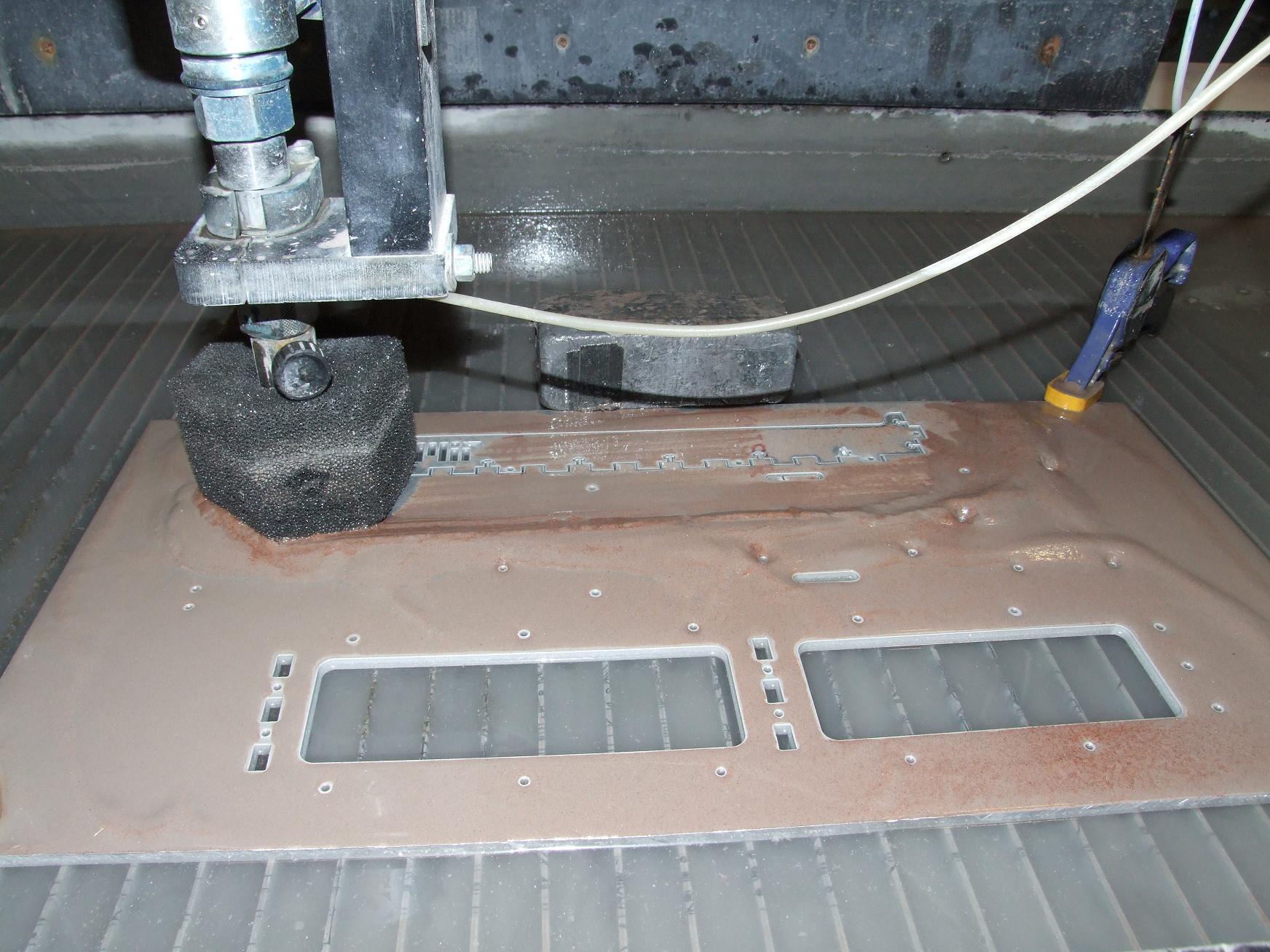
I carefully tiled all the parts onto my four spare 1/4″ thick, 12″ x 24″ 6061 plates. These were all leftovers from the robot builds, collected over the past several build seasons. As it turns out, 4 plates was just enough to fit all the structural components on and still allow for fixturing area and dead space.
Next, it was to pop the entire frame out on the Machine Without Which I Am Nothing. I pretty much devoted an afternoon to a marathon waterjetting session in which all the parts were cut without incident. Now, I’m pretty traumatized by the complete loss of heavily tiled parts in the past, but this time, the worries turned out to be unfounded.
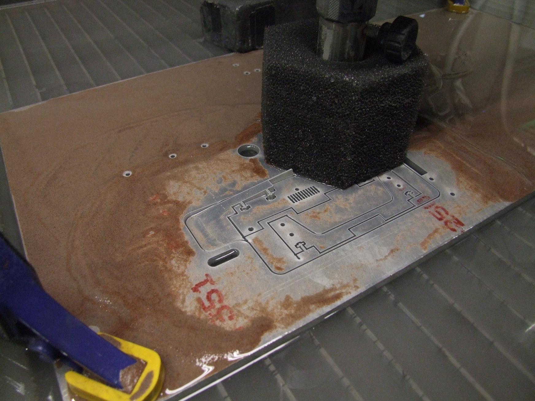
Well, mostly. It helps that I was careful and kept a close eye on everything. This could easily have turned into a nasty situation – the closely tiled parts on the inside of the perimeter caused the nozzle lead-in to separate the scrap into two pieces… one of which proceeded to jut upwards.
I caught this moments before the machine was to make a pass to the left again. After every part outline finished cutting, I’d retrieve it out of the plate for peace of mind. That usually unnecessary action probably saved this whole plate.
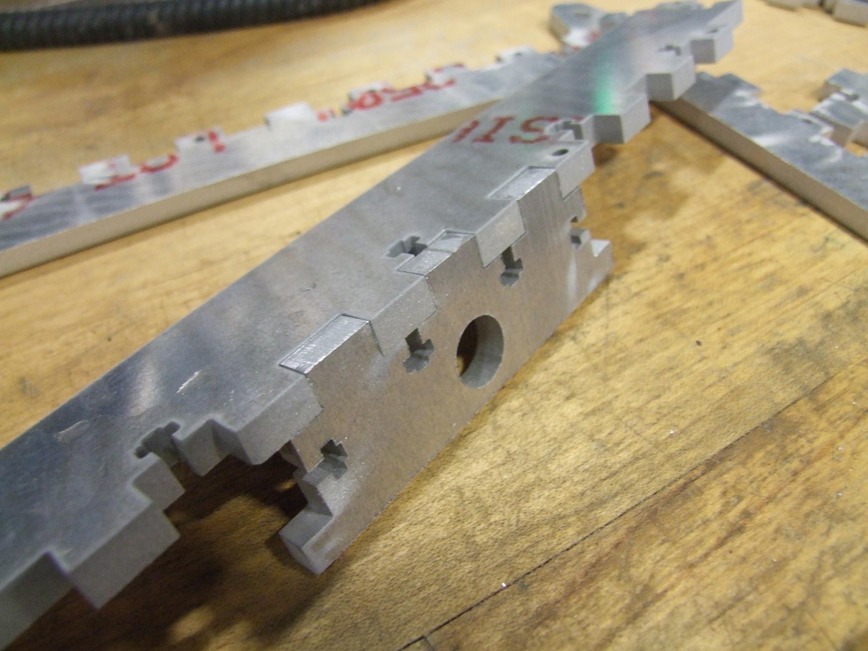
Something I decided to play with on this build was the nozzle offset setting on the machine. Normally, the machine tries to stay one nozzle radius to the right or left of the cut line to finish exactly on dimension. In the past, I’ve accepted that the draft angle that results from such an action causes my tabs to not fit into their matching slots – while the nozzle side face is on target, the bottom could be as much as 4 or 5 thousandths larger on a 1/4″ thick part.
I’ve just dealt with the sanding and occasional light machining that is a consequence of this. But after observing how well the Cupcake parts fit together, I realized that I might as well try to see if I can get even more lazy by not even having to sand the parts afterwards.
Because Makerbot Industries cuts the vast majority of their parts with a laser cutter – which cuts on the line, ignoring the kerf offset, holes and slots are always slightly bigger, and tabs always a little smaller than nominal dimension.
I changed the offset a thousandth of an inch at a time – normally it’s set to 0.014″ for a .028″ diameter orifice. I started turning this down to 0.013, then to 0.012. At that point, I could just push the two parts together for a perfect fit. If you’re keeping track, that means my ODs are 0.004″ in total length (two offset…offsets) smaller on average and IDs are .004″ larger on average..
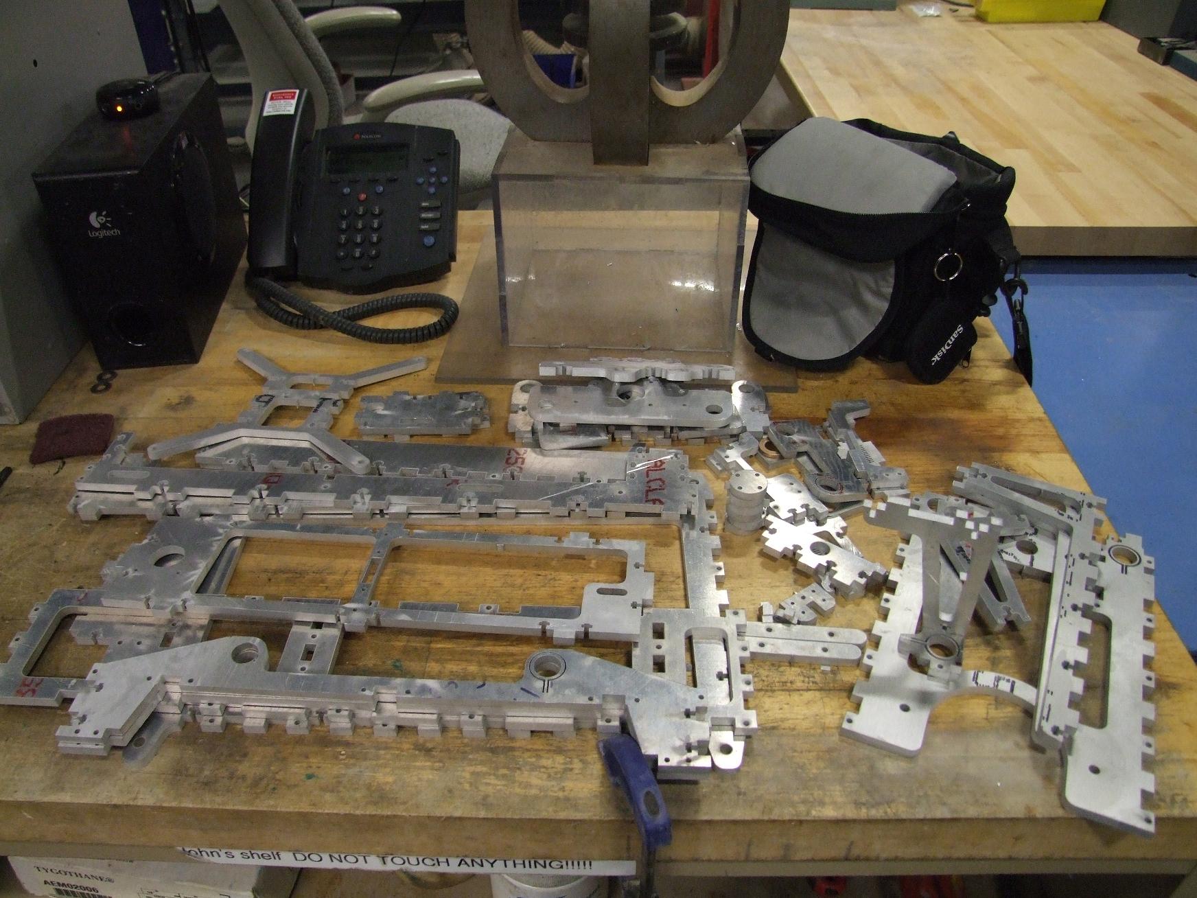
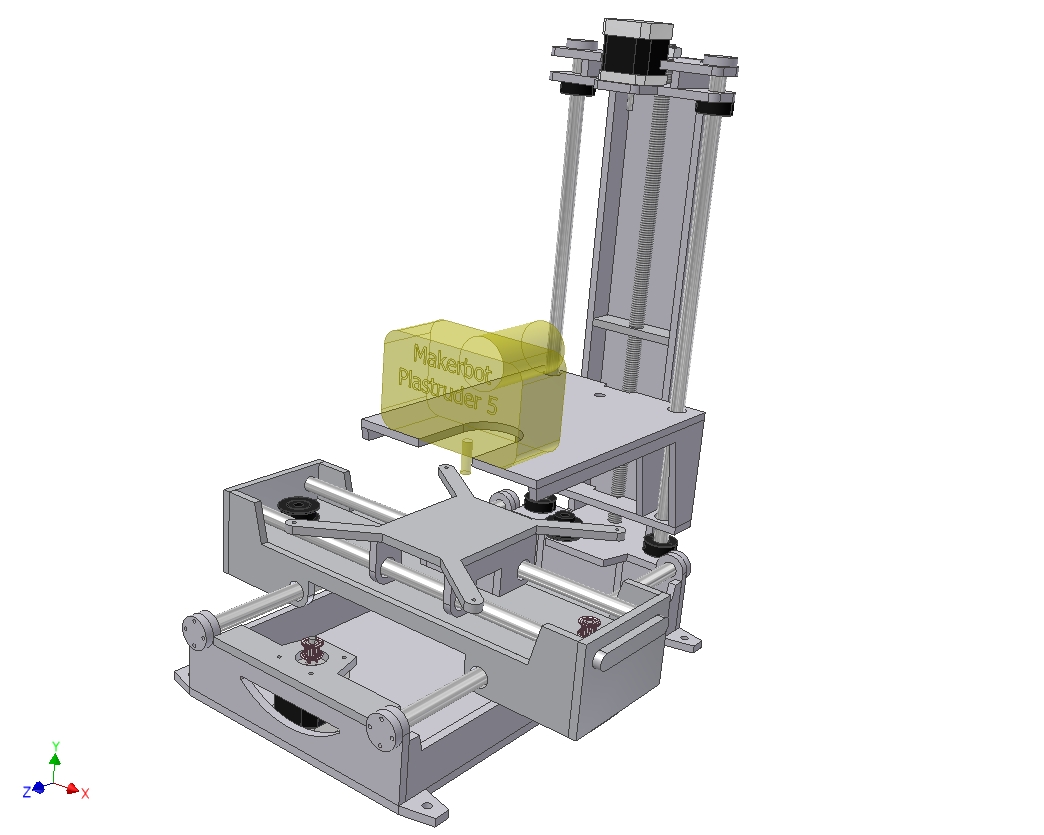
So this is what a pile of MaB looks like. That’s all the parts I have designed so far…
Oh, so I never let a post involving waterjet cutting go without mentioning Big Blue Saw at least once. You, too, can have your own pile of MaB (or pile of anything you feel like designing). I’ve been so utterly spoiled by MIT’s multiple machines that some times I forget about the fact that not everyone has access to one…. and some times, the next best thing is to just hire it out. Surprisingly enough, it doesn’t cost 9 billion dollars per part, and for larger quantities you practically break even on the foregone material cost.
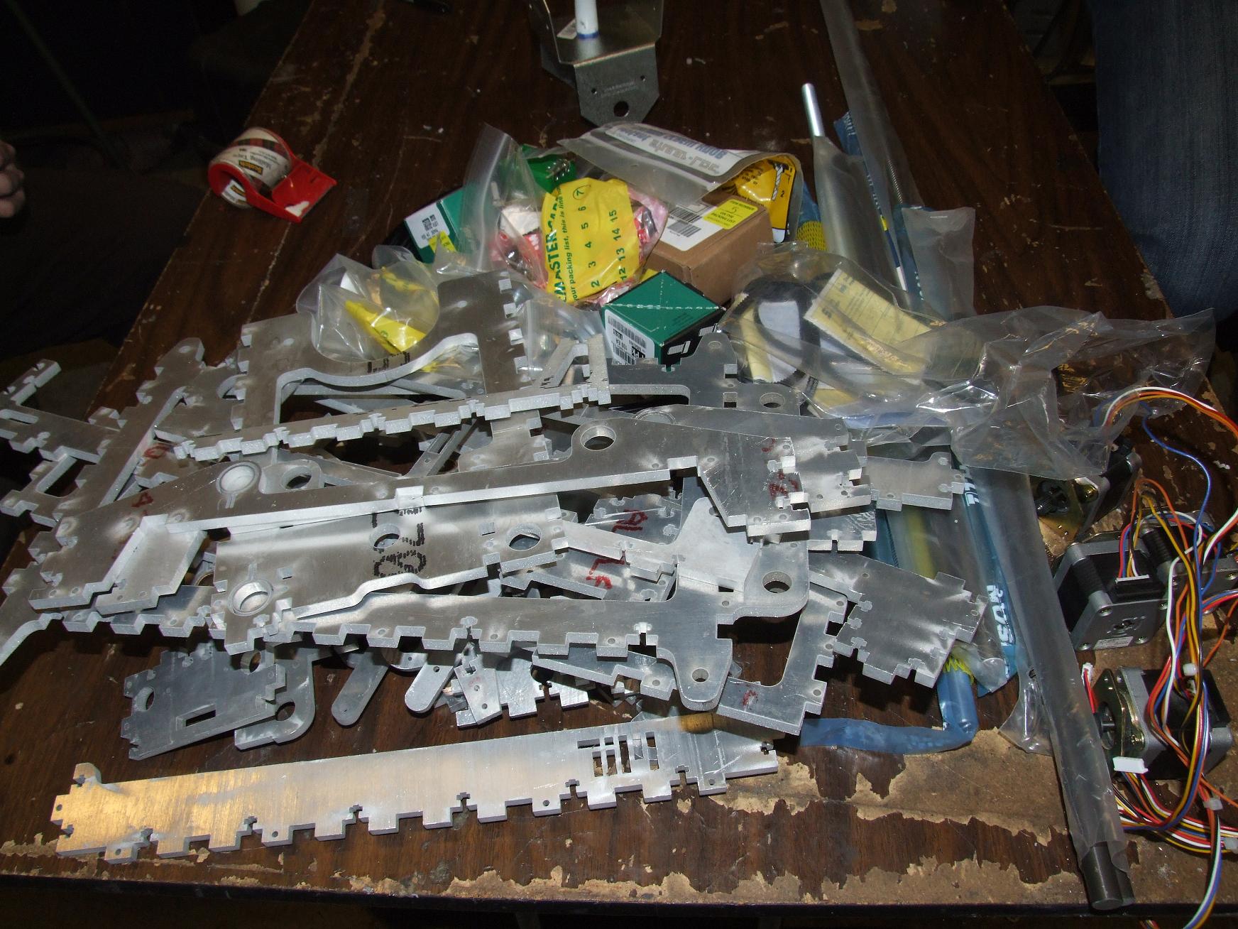
Now merge into this pile a second one of McMaster, SDP, and Ebay orders that had accumulated over the past week or so, and dump it all on a table at MITERS. This is (about 50% of) Make-A-Bot, the other half being the electronics and the software that actually makes it move. You know, The Course VI Part Of Things that I have to deal with every time I build something, since as a Mechanical Engineer I absolutely must build complicated cross-discipline coupled systems projects with electronics in them somewhere.
The McMaster orders contained the majority of hardware, including fasteners, the axis guide rods, bushings, bearings, etc. I nabbed 4 NEMA 17 long-case stepper motors from eBay, which should have about twice the torque of the stock Cupcake CNC motor – hopefully more than enough to muscle the heavier aluminum frame around. Next, from Stock Drive Products, were the two X and Y axis belts and several 44 tooth and 17 tooth timing pulleys.
Alright, so I’ve cut myself a puzzle. Now let’s start putting it together.
The time: 7PM
Because of my “compensated kerf compensation”, everything sort of fell together. For the sake of convenience, I dashed some of the parts over a belt sander anyway for a free-slip fit rather than a push fit. I figured all of this has to come apart again eventually because I installed something backwards.
(I did.)
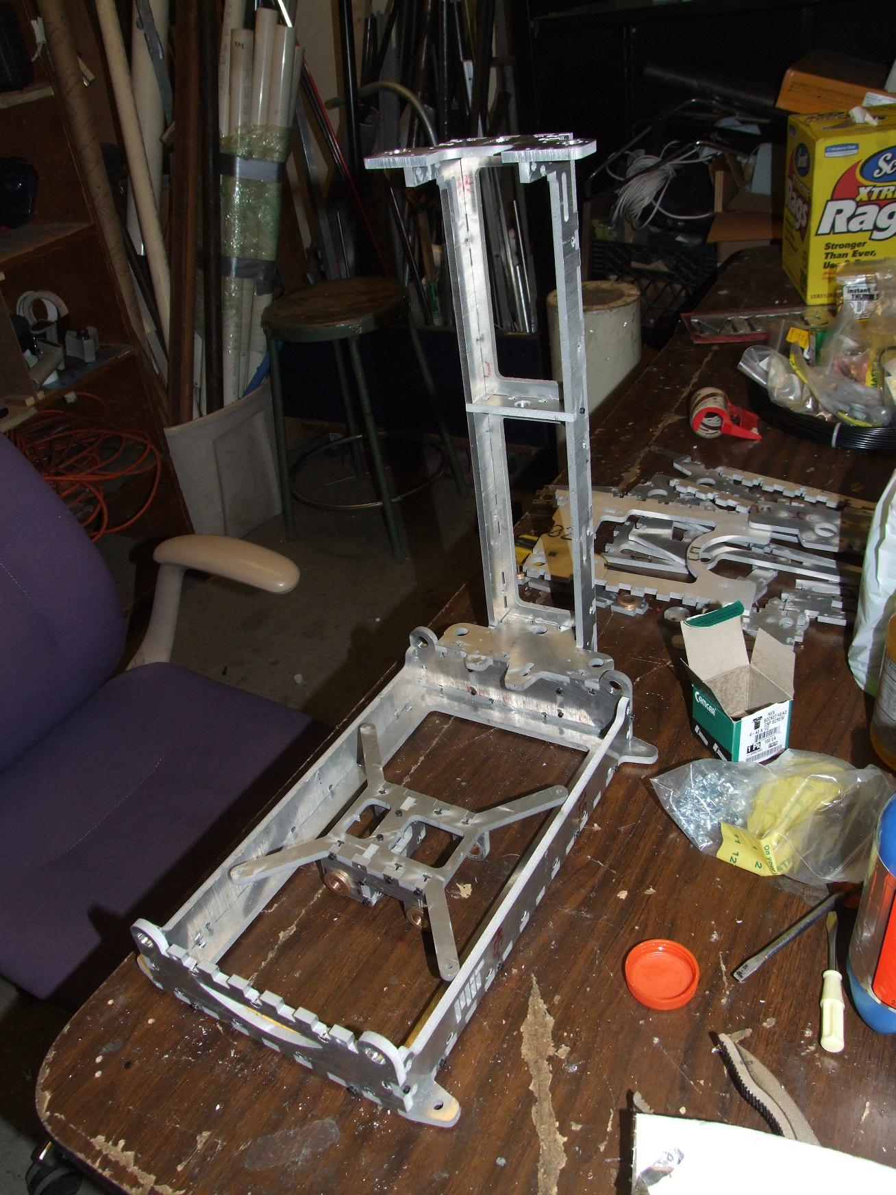
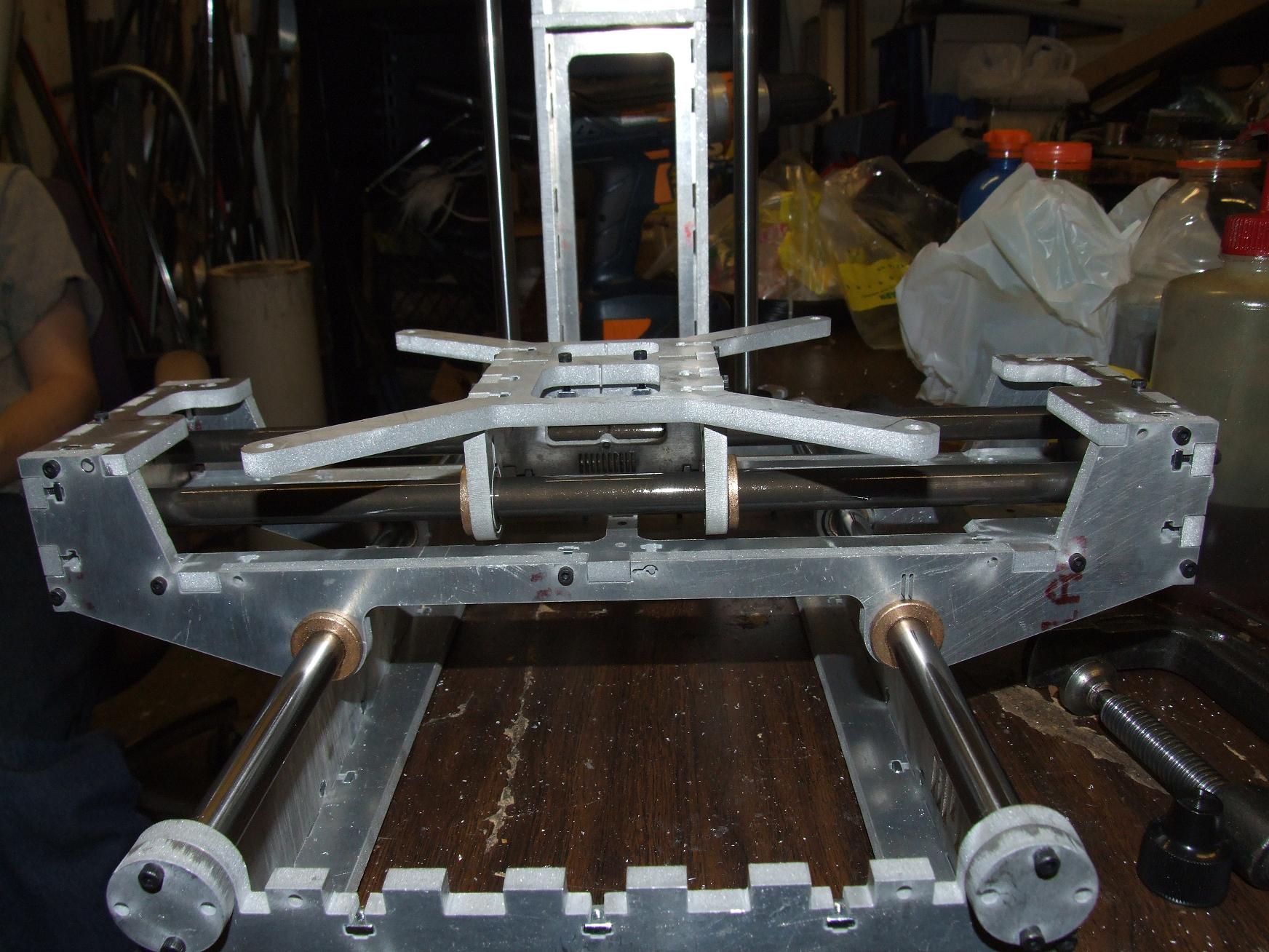
Above is the base and some of the Z-axis tower assembled, but relatively unfastened.
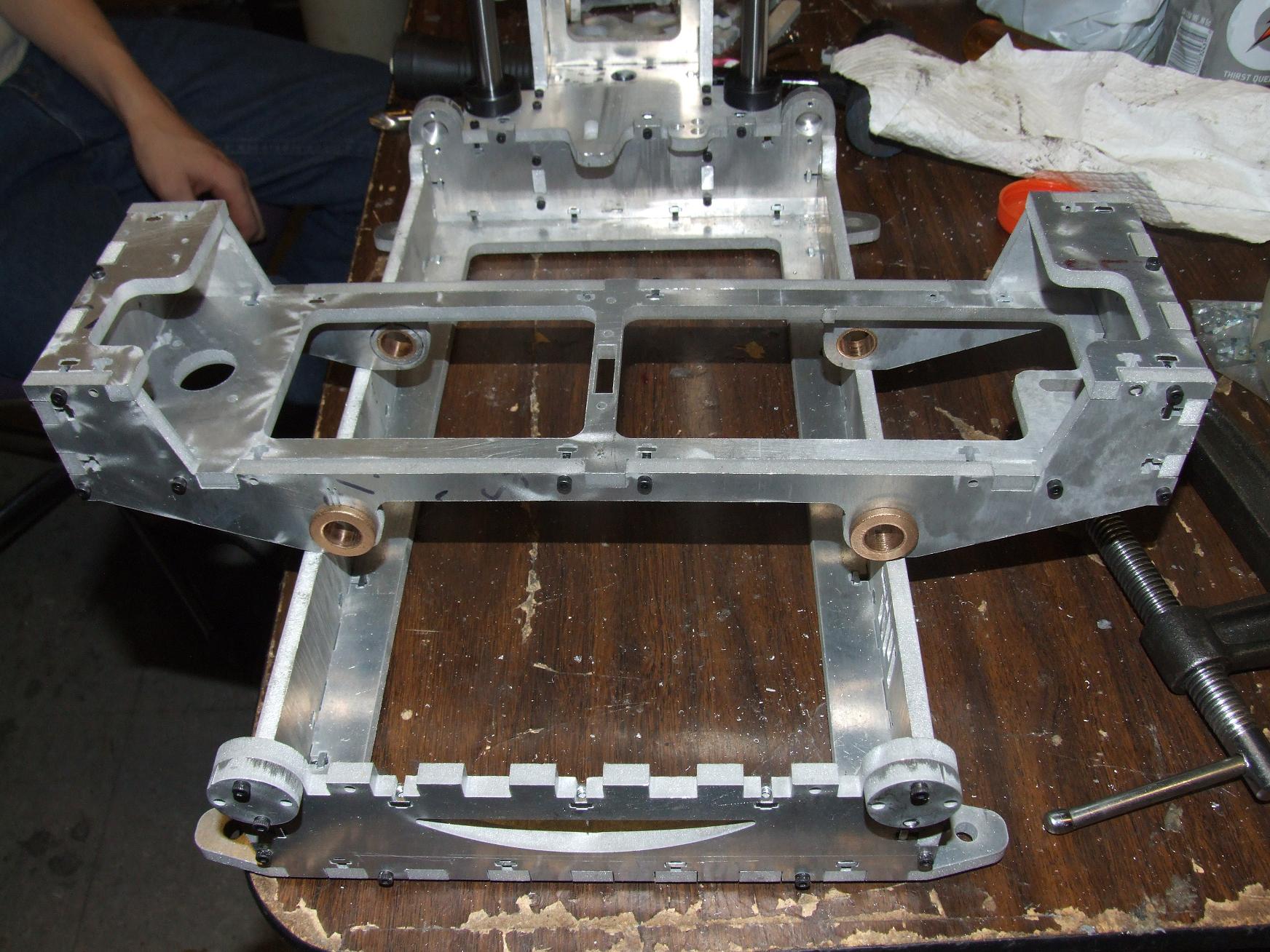
The X-axis stage holder is probably the best finished, most well-kerfed assembly I’ve made yet.
As usual, blitzCADing means I left a few details out. For example, while I made these cute frog-eyed axis rod stops, I neglected to transfer their hole pattern to the actual front and back baseplate walls.
Oops. I guess that’s what a clamp and cordless drill are for. The rod stops were clamped onto their anticipated final location and then #4-40 tap drilled.
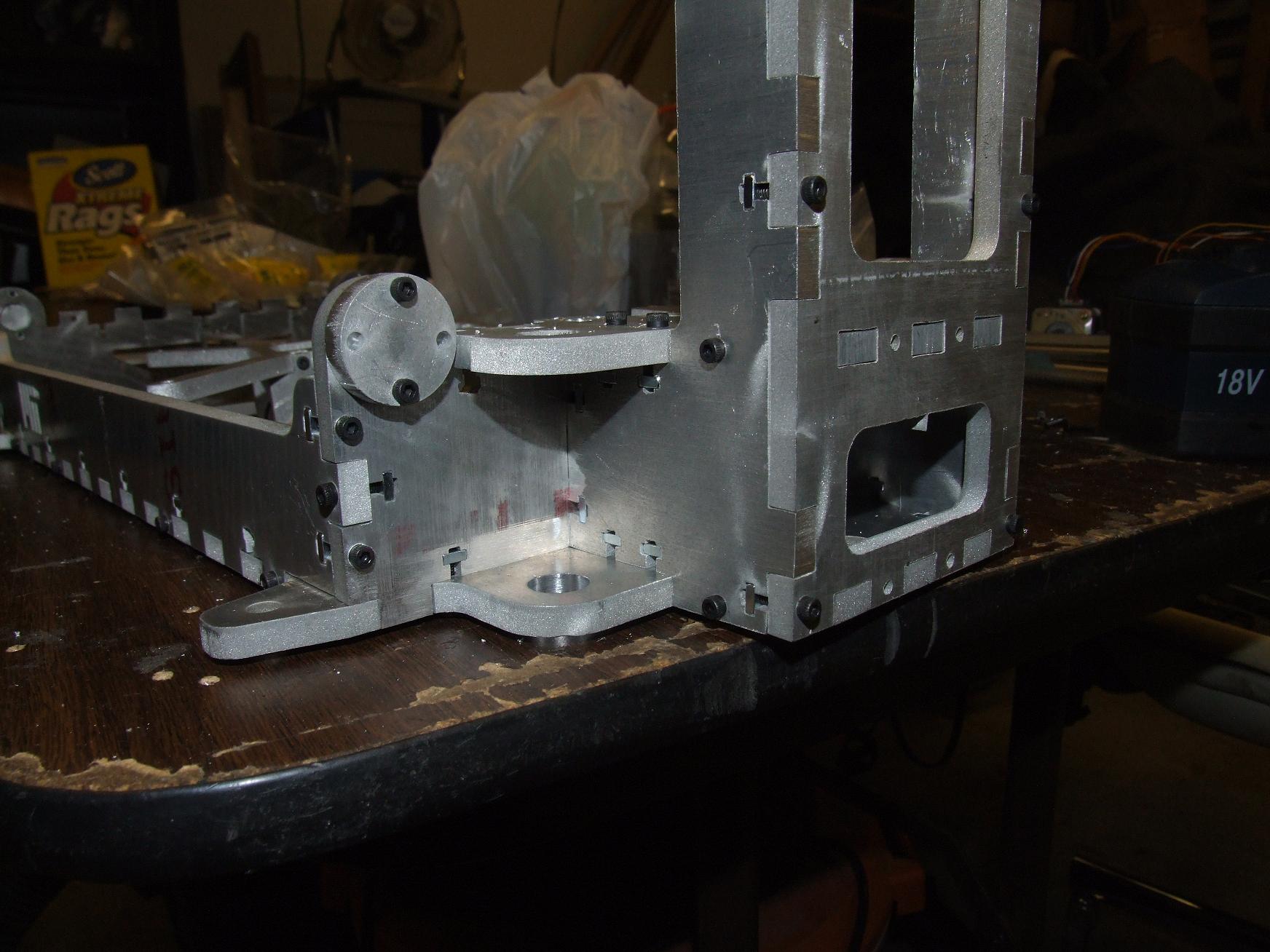
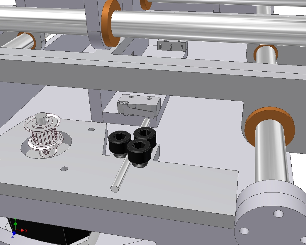
The action’s picking up a little now. This is the whole Z axis attachment point, with an almost terrifying amount of interleaved T-nuts. Some of these things MUST be redundant.
I didn’t care. Square nuts are easily slipped in from the side, and I’m going to wager that Z-axis fine alignment can be changed by selecting which nuts I tighten.
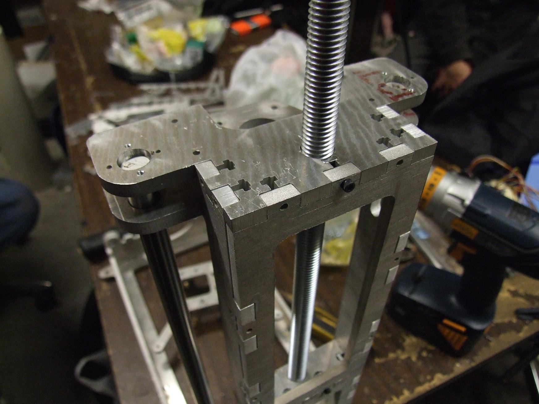
After I fully assembled the Z axis tower, it was time for the Pass-or-Fail-at-Being-a-Mechanical-Engineer test. By that, I mean dropping the Z linear guide rod down the holes which are supposed to support it, and see if it falls all the way through by itself.
Okay, so I cheated: All nominally 0.500 holes in aluminum were given a run-through with a 0.505″ reamer. I was after the slip-fit, not a press fit or shove-fit, again for convenience of assembly. All the bronze guide bushings were also given the same treatment. After pressing them into their carrier holes, their IDs deformed enough such that they no longer mated with the guide rods. A pass with the reamer in a cordless drill cleaned up the bores again to something freely sliding.
After that, both Z axis guide rods made it all the way to the bottom without incident. The compression rod is also shown (That’s not the Z axis leadscrew – it’s just a threaded rod that will be used to load the Z-axis tower in compression)
After the Z rods went in, I pitched together the Z stage. The bushings had already been given the once-over by this time, and the assembly… compiled, I suppose, with the help of a rubber mallet.
And it was beautiful indeed. No stick-slip, no jamming, no tight spots throughout the travel. I was very surprised it turned out this way, and I’m willing to bet the flexure bearings are accommodating at least some movement that would otherwise have caused total disaster. But with the Z axis rods as well-aligned as they are, maybe not?
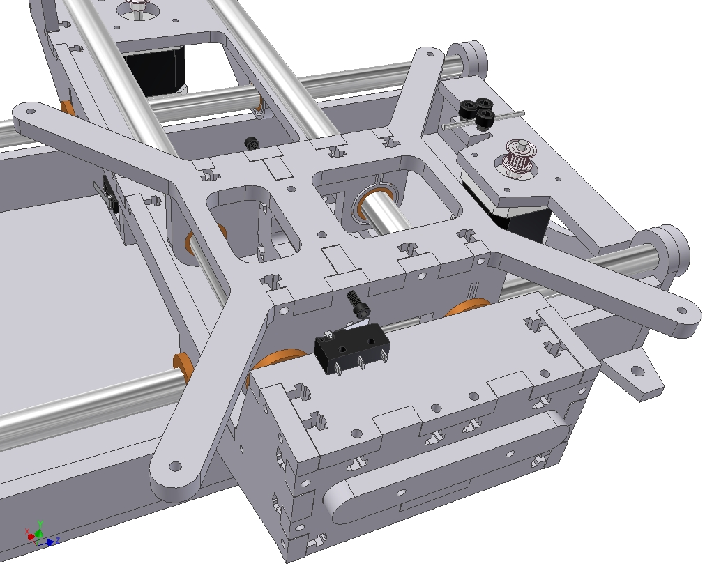
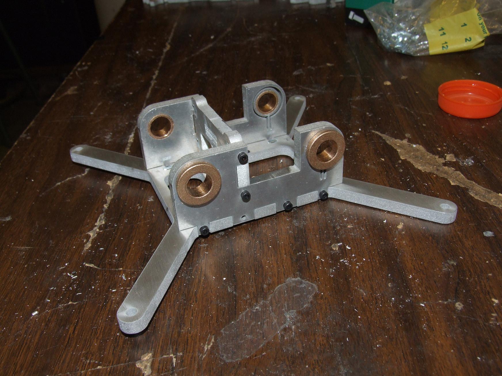
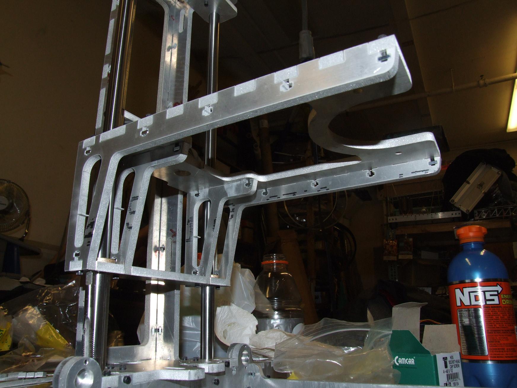
After securing the base and the Z tower, I moved on to hammering the Y axis carriage together.
Here’s a quick assembled view of both axes. The Y axis motion is also extremely smooth. Due to its lack of gravitational preload in a convenient direction, there’s some stick-slip between the bronze and the polished steel, but it’s nothing a dose of Teflon-bearing oil didn’t fix. That, or just some exercising and running to fit the two cylindrical surfaces to each other.
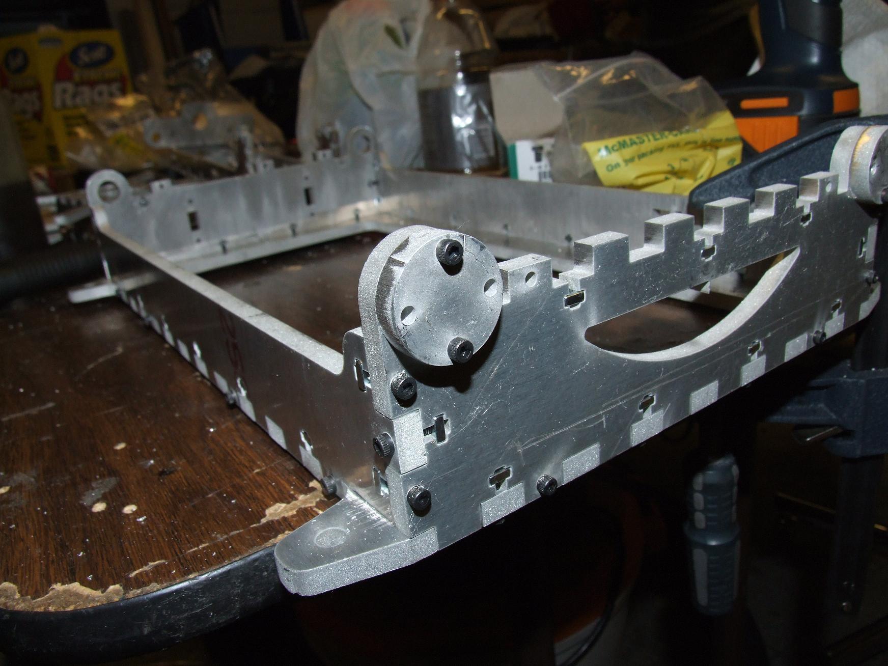
After slipping the carriage onto the Y-axis rods, I installed the X axis guide rods. Note that they’re a different color and texture than the smooth steel Z and Y ones.
Out of the interest of reducing axis inertia, I elected to try some ceramic-coated aluminum guide rods. McMaster priced them out at just a dollar less expensive than a case-hardened steel rod of the same length and diameter, but the primary motive was to try and save the pound and a half that was the difference between the aluminum and steel. The coating on the aluminum is supposedly harder than the equivalent case treatment on a steel rod.
But after trying them out on the X-axis stage, I’m not sure if I like this setup. The bronze bushings exhibit strong stick-slip with the coating, even with a healthy dose of oil… and it even seems to be scraping off bronze onto the rod surfaces. My guess is that while the ceramic coating is harder than the steel, it’s not smoother. The case hardened steel rods have been subject to some pretty intense polishing.
I wasn’t nearly as satisfied with the X axis feel as much as the Y and Z. As a result, if axis inertia proves to be a false demon, I’ll just switch back to steel. Sadly enough, they don’t make hollow steel shafting in this size.
Otherwise, there’s always ninja linear bearings.
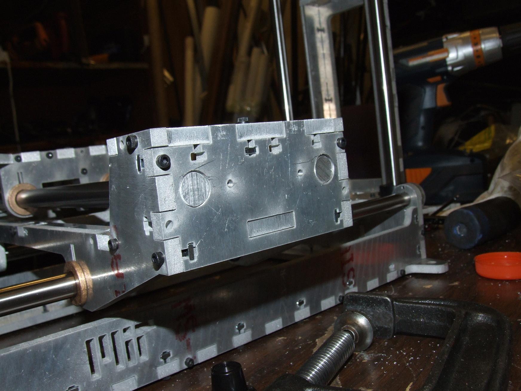
The coated aluminum rods only came in 13″ and 15″ sizes for whatever reason, and I needed 14. So enjoy this cute robot face that is the result of trimming the rods to length.
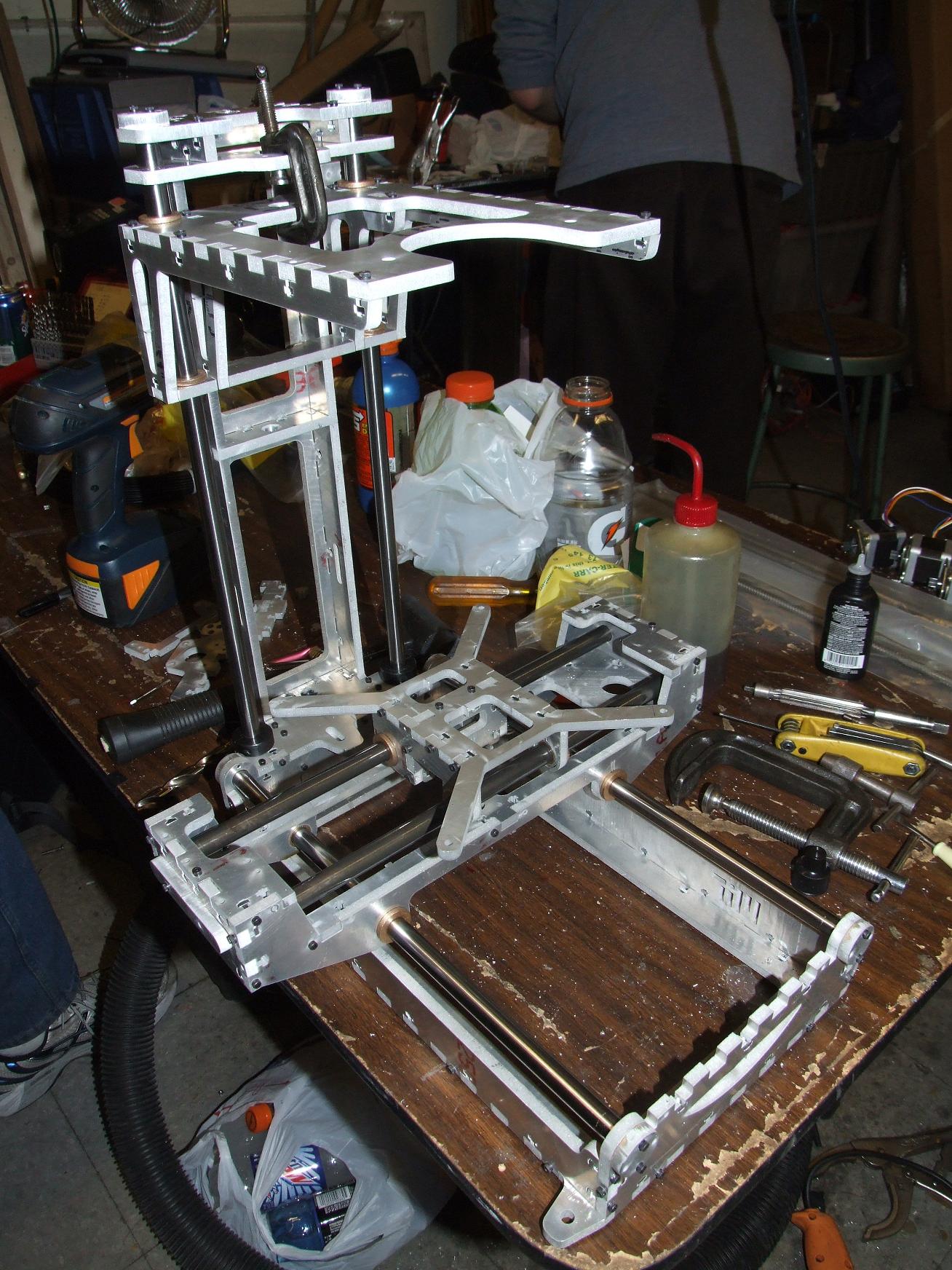
Enough silliness. This is where the hardware stood at 2 AM, after 5 net hours of assembly time (because there’s always things to distract yourself with at MITERS). There is currently no…
- Head
- Motors
- Belts
- Pulleys
- Leadscrews
- Motherboard, driver boards, extruder controllers
- … or anything else, really.
Oh, speaking of the leadscrew, I’m 99% certain that the new Thing-O-Matic uses a 3-start “rounded” ACME threaded rod and matching flanged nut, 3/8″-12 diameter, for 1/4″ of vertical travel per turn. Makerbot Industries hasn’t released details yet, but I extracted what I could from all the up close, almost pornographic images I took of the 3d printing exhibits at Maker Faire.
Example: McMaster 6350K151 and its matching screw, 6350K113. Problem? The screw only comes in stainless steel, in 6-foot sections, at a shiny $133 each.
…
No, not happening. So what else goes 1/4″ per rotation and is 3/8″ in diameter? A two-start 3/8″-8 ACME leadscrew, of course. I’ve spec’d out McM 99030A315 for the leadscrew and 95072A126 for the nut.
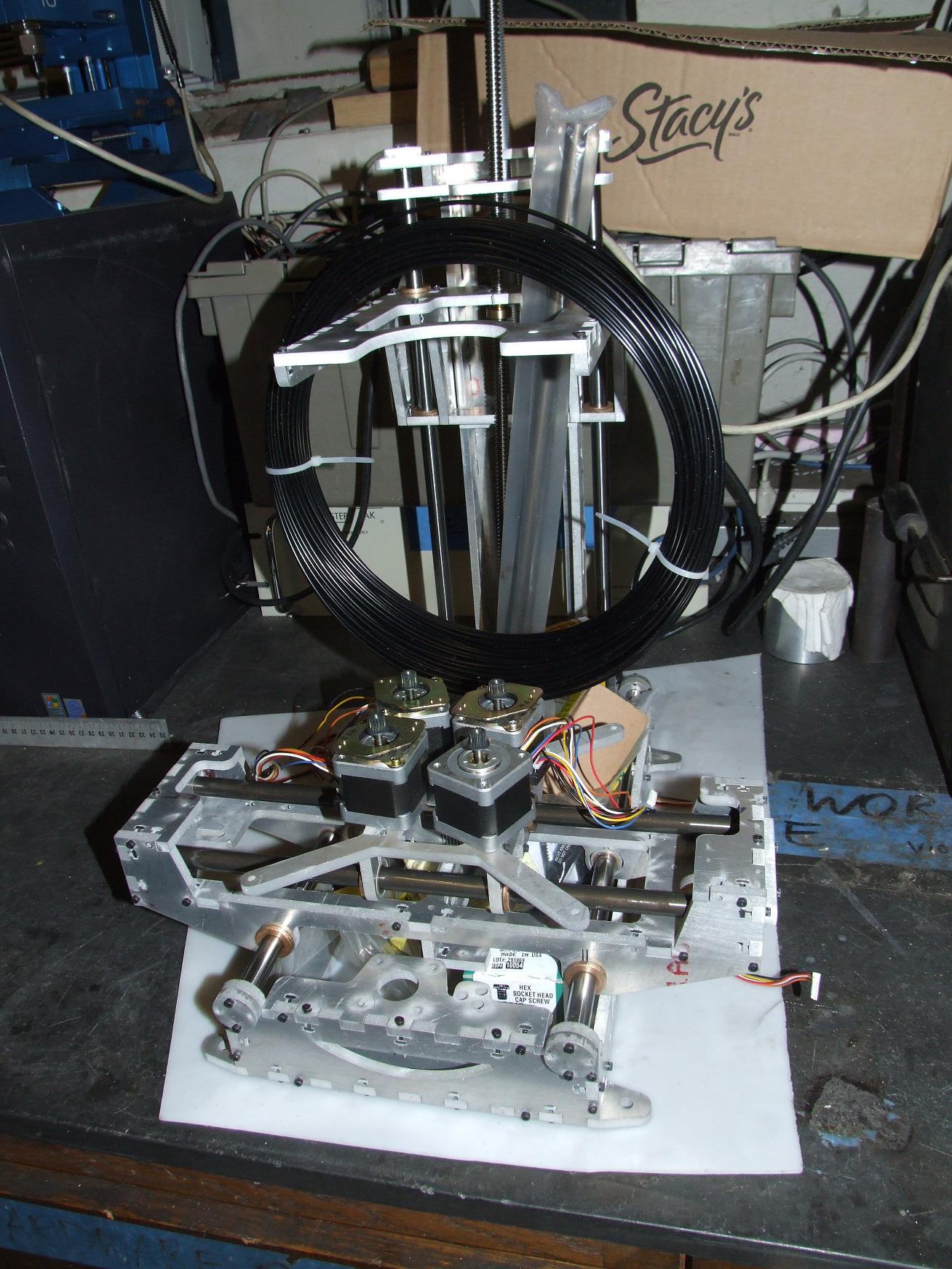
I piled everything onto the base and slipped it in an empty corner for now. Until another day, Make-A-Bot!