Hey everyone! It’s time for another “Did I say later… I mean like now“! Recall this from a few weeks ago:

Going above, beyond, and way further on the highway to collect dumb shit than ever before?
I decided that it was so simple and required so little fabrication that I might as well do it in the post-semester downtime when the students all go home continue to use the shop for their own derpy projects, but luckily they don’t involve my oversight as much. It also presented me with an opportunity to finally use one of the One Thousand Hobbyking Amps ESCs, and I got to try the “mechanical waterjet” on aluminum to test out how well it was able to perform; even though it’s not really meant for that.
So here’s what it is.

Here it is on the dissection table in preparation for removing the existing powertrain.
What it comes with:
- 12v lead acid battery
- “80W” generic scooter motor – it metered 0.18 ohms, which means this motor could actually push quite some power. I couldn’t find these on sale anywhere, so they might have been a one-off made for this vehicle by Razor by Unite Motor (which makes OEM motors for Razor)
- On-or-off controller that was really your finger switch pulsing a relay. Finger-PWM!
- Roughly 8.5:1 reduction, belt drive. I found this impressive since it means I could easily make use of it for sensorless drive, to which a high gear ratio is crucial.
What it’ll get:
- 25.9v (7s) lithium battery, from my Nuclear Arsenal
- Hobbyking “200a” controller. I decided to start with the “Birdie” model.
- A left over T600-880 motor. It was way too fast for the application, but is the closest hardware direct swap!

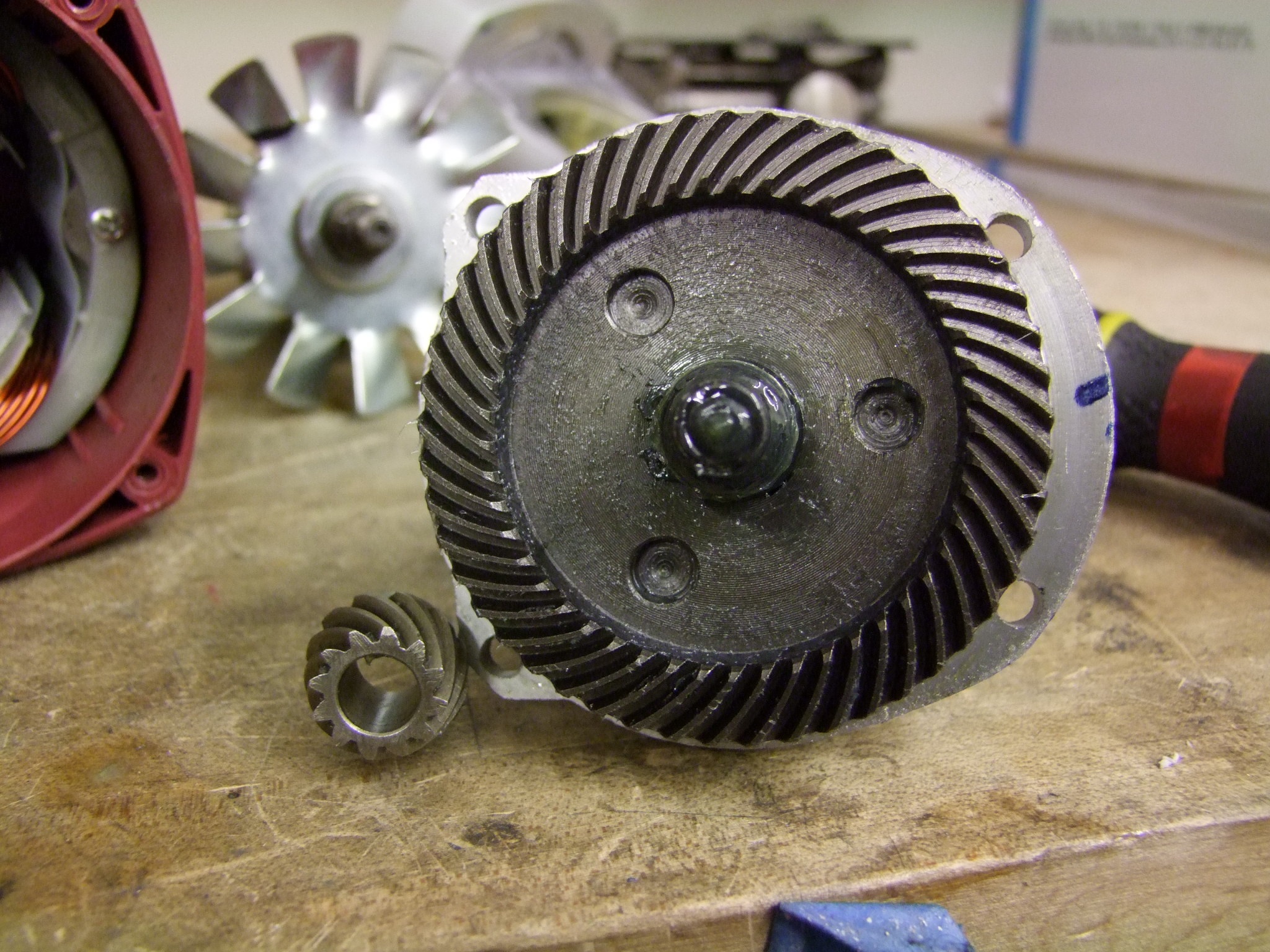
The big plastic belt cover comes off to reveal the driveline mechanics. They put quite a lot of engineering effort into these, so I’m sad that these things are no longer being sold. An adjustable sliding motor mount and a real spring-loaded belt tensioner, commanding a quite unconventional 14mm wide 3mm HTD belt (size 549-3M-14). Typical 3mm belts are only 12mm wide. I was only about to find the belts listed specifically for this vehicle, so again it might be a dedicated thing for Razor.
I designed a quick mounting plate that adapts the T600’s 25mm bolt pattern to the 56mm pattern of the original motor:

I was going to lob it at someone in MITERS to sneak onto one of the waterjet cutters, but somehow this felt immoral. One thing I had been itching to try was cutting metal on our Shopbot PRS Alpha. It’s something which has been done in limited amounts and generally very slowly, often on thin material. The Shopbots aren’t metalcutting machines by design – their construction is lightweight aluminum extrusions and little wheel guides on steel rails. This doesn’t lend itself to maximum rigidity or vibration damping.
Here’s where I found out that our machine has a bit of head backlash- look at the oval flattening of the holes. I guess I’ll have to dial it out now.

I drilled and screwed a spare 1/8″ plate onto our cutting bed and sprinkled the area in cutting fluid to keep the cut cool. Another reason why I’m not about to buy aluminum in 4 x 8 foot plates is the lack of a coolant system and chip extraction system – the vacuum next to it isn’t gonna do that for you. If this becomes a more common practice, I might try to invest in a standalone mist cooler, which doesn’t make a huge lake of coolant and delivers just enough to keep the bit clean and cut area lubricated (Example)
Using a feed and speed calculator, I came up with a conservative feed rate and spindle speed assuming 0.001″ of cut per tooth – pretty light. Using an 1/8″ carbide endmill, I was going to run it at 30 inches per minute at 10,000 RPM.
It broke pretty much instantly.
I’m going to guess that the machine just can’t absorb that level of force and not vibrate, which is weird, but when your bit is brittle and tiny, even a small amount of vibration will destroy it. I began at 50% of that speed (15 IPM) and gradually put it back up to 20. In the picture of the two parts, the left was done at 20IPM and the right at 15IPM, and the right one exhibits better surface finish.
I suspect dialing out the backlash and tightening the axis rollers more will help it, but it seems that slow and steady with a “one flute” cutter wins – check out the work by this crew.
Anyways, the “is this insane” part of the mission is complete with a satisfactory part, so I’m good for now.

The adapter plate and motor installed!
To make an adapter for the 6mm D-flat shaft of the motor to the 8mm D-flat shaft of the pulley bore, I turned a piece of aluminum tubing to a 1mm wall, cut off an arc with a Dremel tool to make it the rough proper circumferential length, and then mashed the pulley and motor and itself together on an arbor press. The 1mm tubing section cold forged into the shape of a D-flat that bridged motor and pulley, and all was good!
I wouldn’t send it into space, but I would totally send it down the hallway.
The slot is to pass the pre-assembled motor and pulley through, because the pulley flange was too large to fit between the mounting holes, and the arbor press installation was pretty much a one-shot thing.

A better view of the motor installation, with the same M4 screws it came with.
Moving onto electronics:

I whipped up this really quick housing to be made from on-hand high density fiberboard. It served two purposes – first, I hate zip tying electronics together (and explicitly ban it in 2.00gokart!), and I was going to actively fan cool the controller, so it needed a “wind tunnel” of sorts. This thing hangs down on the center frame tube and is secured by some circular sectors with matching holes. The fan is mounted to the left (the front), and the controller sticks out the rear. I designed it to cradle the controller by the output wires.

For signal processing, I brutally butchered a small servo tester – cut the LEDs off, cut the mode button off, and cut the potentiometer off. I only used a soldering iron to clear the potentiometer’s pin holes to add my own 3 pin cable. The potentiometer’s voltage output is to be substituted with a typical small EV throttle (example).
These little testers swing from about 900 to 2100us with the pot’s 0-5v output, so with a typical Hall sensor throttle’s 1-4v output, I’m still in a reasonable range to interface with the R/C controller. This is the quickest way to get set up with an R/C power system – more details can be found, of course, in Scooter Power Systems.

The ESCs I got in the Hobbyking vivisection post are all “Opto”, meaning they do not supply power to the receiver and they take signal in through an optocoupler (hence the name).
Well, first off, there’s no optocoupler – in Hobbyking language, these “Opto” ESCs just have all the parts for an onboard 5v power supply taken out for cost reduction.
Smart. Well, there’s always a very small 5V supply – the microcontroller’s own power regulator. It’s too small to run any servos or bright LEDs, but if you only need a few more mA to run said servo tester, then it’s an easy wire jump from the 5V regulator to the red wire of the servo signal cable! In these applications, the regulator is already very heavily stressed (they’re not supposed to be dropping 20+v on their own), so a small auxiliary micro is about the most that can be gotten from it.
Now, to be fair, it’s not true for all of them – most of the higher value controllers, such as my eternal favorite the 100A Sentilon, have legitimate optocoupled signal inputs and isolated grounds. For high current applications, it can greatly reduce noise glitching.

I bunched the old heat sink back on, in a less precarious location (recall that they ship with the heat sinks touching the output solder blobs), and threw a new heat shrink shell around it.

This leftover 4400mAh 7S Thunder Power battery from the DERPA robot fit perfectly in the 12V lead acid tray. It was so perfect that I just used some Velcro cinching straps (not zip ties – never, ever zip tie your lipos) and it sort of hangs out there, oblivious to all that is about to occur.

I needed a 12v rail to drive the cooling fan, which was not going to tolerate 26+ volts straight from the battery. I decided to check if my collection of cheap HV 5 volt BECs was hackable to yield 12v. The answer is yes, and I’ll keep it as a separate section under Beyond Unboxing, so for now, this is the 12v DC to DC converter!

The electronics box was laser-cut from 1/8″ and 3/16″ high density particleboard. This stuff is actually reasonably strong and water-resistant – not like Ikeaboard. I am still on the hunt for a high strength laser-cuttable plastic that isn’t either terribly messy (ABS, PETG) or expensive (Delrin). Or really soft and plushy (Polyethylene). For now, wood was fast and someone left a plate of it without their name anywhere, so it automatically becomes state property.

Here’s where the controller sits.

The 12v DC-DC module and servo tester have been added. That fan is a 40mm harvested server fan – the ones that scream at 10,000+ RPM to move the same air as a big computer case fan, but it’s a server in a room by itself and flatness is more important than being quiet. I whipped up an adapter block and had it 3D printed while the rest of the wiring happened.

A better shot of the fan, as well as a view of the master switching. The male Deans connector is where I jack in the battery; the vehicle is turned on using the “Georgia Tech Switch” that I now use on almost everything that doesn’t matter. It’s also known as a ‘removable link’.

A shot of the completed vehicle! I used left over wiring twizzlers spiral loom from the Electric Vehicle Team to keep the wire bundles neat.
First impressions: It’s very menacing wheels-up when you gun it, but on the ground is a different story. Remember how I said the motor is “too fast”? Basically, the theoretical max speed for this design is 61mph:
- 880 RPM/V at 25V (assuming some loss in the system) to yield 22000 RPM
- Reduced 8.5:1 to yield 2588 RPM at the wheel
- with an 8″ wheel, that results in a ground speed of 61.5MPH
That’s an impressive number to throw around to the uninitiated, but what it means is that at any speed under half of that – or about 30mph – the motor is dissipating more watts in heat than it is giving you in mechanical watts of ass-haul. So, in other words, this thing just pulled 200+ amps and didn’t do that much. The takeoff was still extremely strong, but at the expense of all the wires and the battery being hot within a minute. The controller is only surviving due to forced air cooling.
Despite all this, I rode it home and back a few times for sheer shits. I might even say I love it more than Melonscooter, since it’s so light and nimble. I just had to have a very, very sensitive throttle finger since if I accidentally gunned it, it’s not going to take off without me, but just light on fire.
This stopped being funny within a few hours. I decided that nobody else was ever going to be able to experience the joy of this thing since it would self-eat so easily. And self-eat it did – for some reason, one day Jamison was taking a spin and it made a popping noise and stopped working.
Whoops. Well, it’s time to “downgrade” the motor while I’m at it:

I spent a while on Hobbykong searching for a replacement motor. I decided to try and get the speed down to about 30mph tops – which I assure you is plenty fast enough. I had to juggle which motors were in stock with how much work I wanted to do to replace the shaft (since almost all of these small outrunners have 6mm shafts), with which ones actually had my required RPM/V.
I settled on this 700-class heli motor with 500 RPM/V. It would yield a “max power speed” of 16mph, so you could actually stand a chance at blitzing down the hallway and be able to kill yourself instantly at the end. I also trade an unrealistic top speed for more useable launching torque.

I wanted to do away with the irritating forged sleeve adapter. I had left over 8mm precision shafting, so I turned this replacement shaft on tinylathe and made retaining ring grooves on the right end to keep the pulley on without a set screw (It came with a snap ring on the original motor). The dimensions are otherwise on-the-fly measured directly from the heli motor.

The new motor installation was easy; it shared the same bolt holes as the T600. I replaced the burnt Birdie with the Red Brick.
This thing now really hauls – I can legitimately hand it to someone and have them throw themselves off without potentially destroying anything. Not to mention that it somehow became 100% practical too! The suspension and pneumatic tires means it’s actually very smooth in handling bumps, and a little exciting in acceleration since it compresses and you are not sure if it will keep compressing until you land on your head. Just don’t try to stop. It has 1 brake, in the rear, and your center of gravity makes it lock up if you are even thinking of stopping.
eNanoHerpyBike (because it’s electric and smaller than Herpybike to the left) is up for some test video soon, whenever it stops being disgusting outside. I do have some hallway footage, but this really needs space.
That’s all build-report wise. I said, super simple and minimal fabrication. I’m truly sad that these things are now getting rare.
Beyond Unboxing: Turning Cheap BECs into 12V DC/DC units
Now a little more about the BEC hack. This falls under the category of “you might find this useful if you already have $part but want to do this thing with it”.
You can buy dedicated 12V DC/DC converters for your contraption, but they’re either fairly expensive for the job ($30-100+ dollars) or are a fixed, narrow voltage input and output for industrial use. Good quality R/C BEC (Battery Eliminator Circuit – originally for pilots who didn’t want the extra weight of a receiver battery) are usually wide-range input switching converters, but they’re tuned for 5V.
Update: For thoroughness, and at reader suggestion, here are some examples of where you might be able to get DC/DC converters:
- Example of a commercial 12V DC-DC module for vehicles – typically found as “golf kart voltage converters”.
- Example of industrial DC/DC converter “bricks” (Vicor is pretty premium stuff)
- Example of a small breakout-board style DC/DC module, very similar to the BEC shown below. This might be more straightfoward for most applications!
Current Logic is one place I’ve gone to frequently for commercial/industrial modules.
End update!
But since they cost $4-5, a little bit of legwork can turn them into 12V units which will often put out more than enough current – 3 to 5 amps – to run gaudy lighting or auxiliary systems.
I have a pile of these inexpensive 8-40v things specifically for robots and vehicles, so I decided to tear one apart and see which resistor I need to jump to get the output voltage to change.

Inside almost all of these, it’s just a small switching regulator chip, similar to the LM2576 – the design has been genericized to hell and back. This one is by “XL Semiconductor“.
The circuit is pretty much exactly the application note:

Essentially, the converter doesn’t actually “know” what voltage you want it to output. It only decides if the voltage at its feedback pin, measured through the divider R2 and R2, is higher or lower than an internal reference voltage (usually 1.23V). If it’s higher, it’ll lower its output duty cycle percentage to compensate, and if lower, it’ll raise the duty cycle. This is a brick simple, classic DC/DC buck converter.

The feedback circuit is right here. The two resistors that make up the main feedback network are R4 and R2 (the small resistor horizontally displaced to R3’s left).
In this application, R4 is what the schematic above calls “R1” (the lower half of the divider), and R2 is… well, R2.
R2 is designated 49B (3.16K) and R4 is 01B (1.00K). Small SM resistors use some god-awful lookup code instead of a numeric ones – here’s a table of them. Let’s see what voltage this yields:
Vout = 1.23v * (1 + (3160 / 1000)) = 5.11V
The way it selects 5v or 6v is by jumping R3 on the board in parallel with R4, reducing the effective value of the low side of the resistor divider,and causing the regulator to sense an artificially low voltage. So it tries to make up for the deficiency by outputting a higher one. The resistor that gets jacked in by the jumper is a 472, or 4700 ohms (4.7K). This results in a net low side resistance of 1.0K || 4.7K, or 824 ohms.
Vout = 1.23v * (1 + (3160 / 824)) = 5.95V
And that’s how you get 6V.
So if I wanted 12 volts, I can do one of two things:
- Keep lowering the low-side resistance value (lesser R1 in the example schematic, or lesser R4 on this board)
- Raise the high-side resistance value (make R2 larger).
To do the former, I would need a R1 (slash R4) of:
R1 = R2 / ((Vout/Vref) – 1) = 3160 / ((12.0 / 1.23) – 1) = 360 ohms
To do the latter, I would need an R2 of:
R2 = 1000 * ((12.0 / 1.23) – 1) = 8756 ohms
Now, most of these datasheets recommend keeping R1 to 1-10K ohms for best stability, so the second option is more palatable. I could use a 9.1K resistor in place of the R2 on the board to get about 12.4 volts.

I didn’t have a 9.1K resistor of any kind. And then, only SMT resistors of the utterly incorrect size and value, a 1206 package (the board uses 0603 package, half the dimensions in every way!).

So I’ll just glob it on sideways. Whatever.
This 10K resistor nets me a extra volt or so:

Whatever ¯\_(ツ)_/¯
What is this, science?!
If I put the 5V-6v jumper into the “6v” position, the voltage becomes about 14.8 volts. In other words, damn perfect for charging a 12V auxiliary battery in constant voltage mode. These things automatically enter constant current if the current load exceeds 5 amps, but they heat up and can be damaged quickly. So, float charge only.
Anyhow, I’m doubtful of the utility of this hack for most hobbyists because it requires SMT surgery. Because the external jumper only adds a different resistor, there’s no Clever Jump It With a Different Resistor hack possible – it’ll need to bypass the internal R to ground to get it done. Adding more resistance to the path will make the voltage differential lower.
To avoid SMT work (trust me, it’s not that bad: sharp, clean tip, and a tweezer), you could solder a regular 1/8 watt small resistor directly to Pin 4 of the chip, the feedback circuit, and just solder blob away the smaller feedback resistors.
Regardless, this is presented in the interest of aiding anyone else who might think of this bad idea in their own quest. I’m certainly ordering a bucket more of these things – I can’t believe I didn’t think of this until now.