What the heck happened to LOLrioKart?

It has been sitting in the same spot since mid-July.

After July, I realized that not a single one of the summe bots was moving yet. So, since Dragon*Con was sort of a Big Deal to me, I decided to drop the kart efforts for the summer.  With the robots having epicly failed at D*C, I tried to pick up the effort again when I returned for the start of fall term.

Tried. Either I have been horrible at working efficiently or the days seem to be getting shorter, but I wasn’t able to make any progress for a while. New obligations, the increased workload of higher level classes, and Semi-Discretionary Time-Spending have kept me mostly away from MITERS.

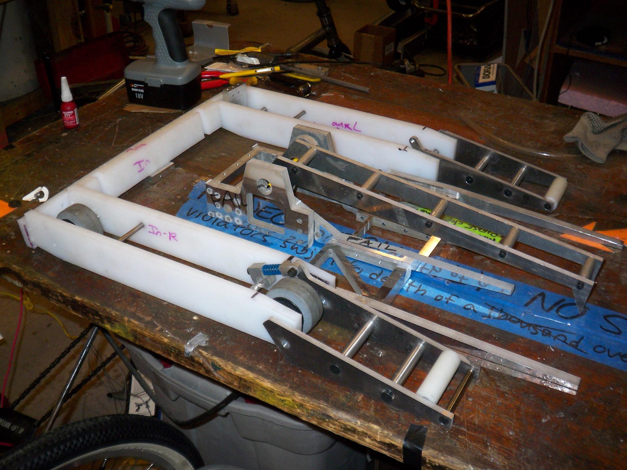
The bottom line is that LOLriokart is still not on all 4 wheels. It is getting closer, however. Here’s the build update, starting all the way back in September.

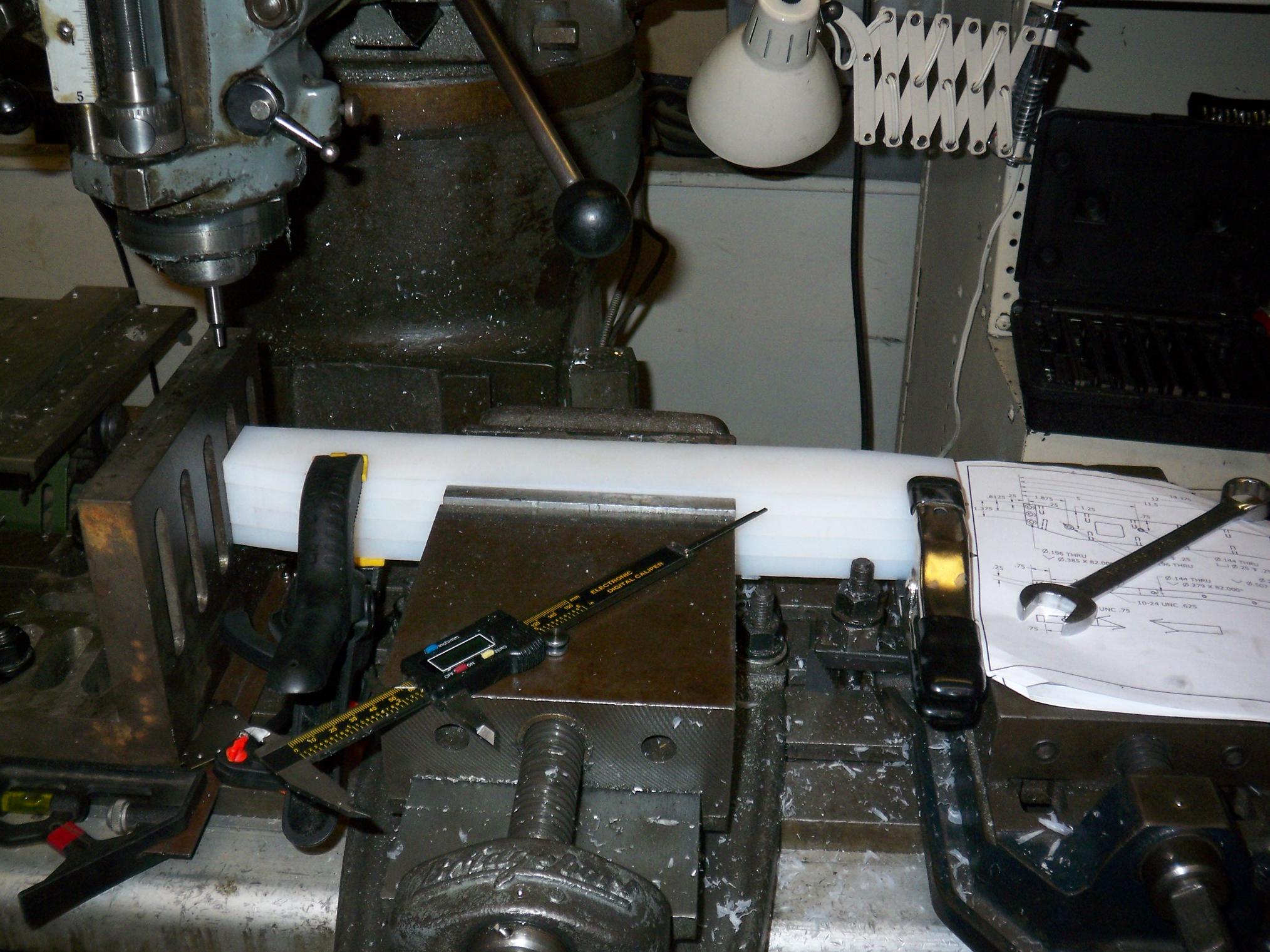
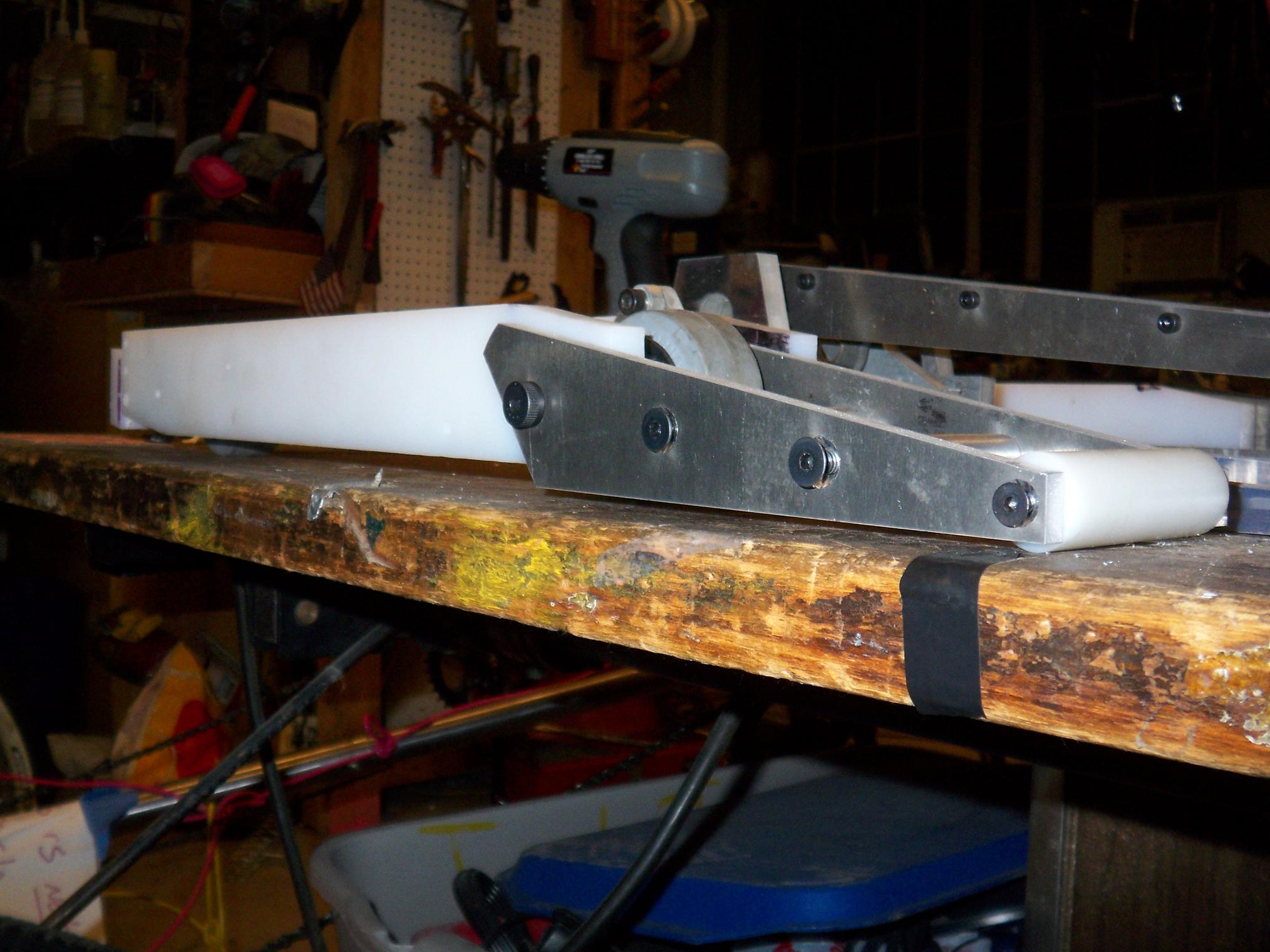
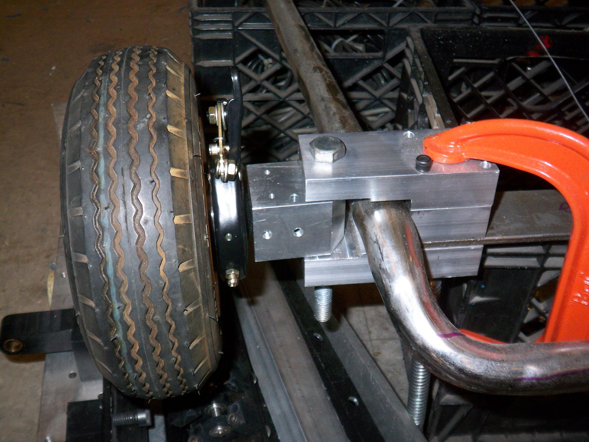
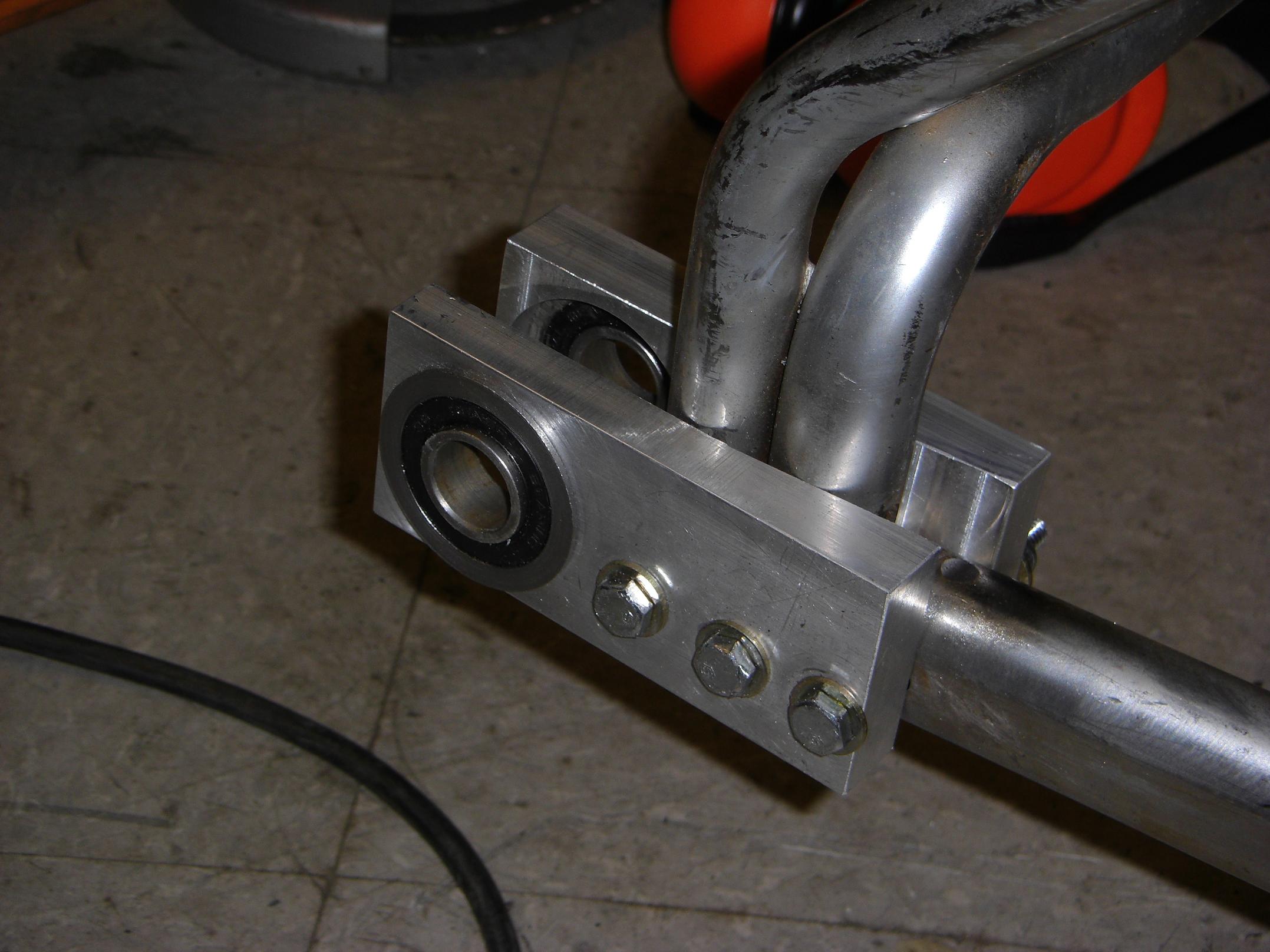
The clamp has finally been removed. New, shiny, properly-sized hardware has replaced the clamps and random found screws. Also visible is the reaction arm for the brake, which is actually more of a reaction slab.

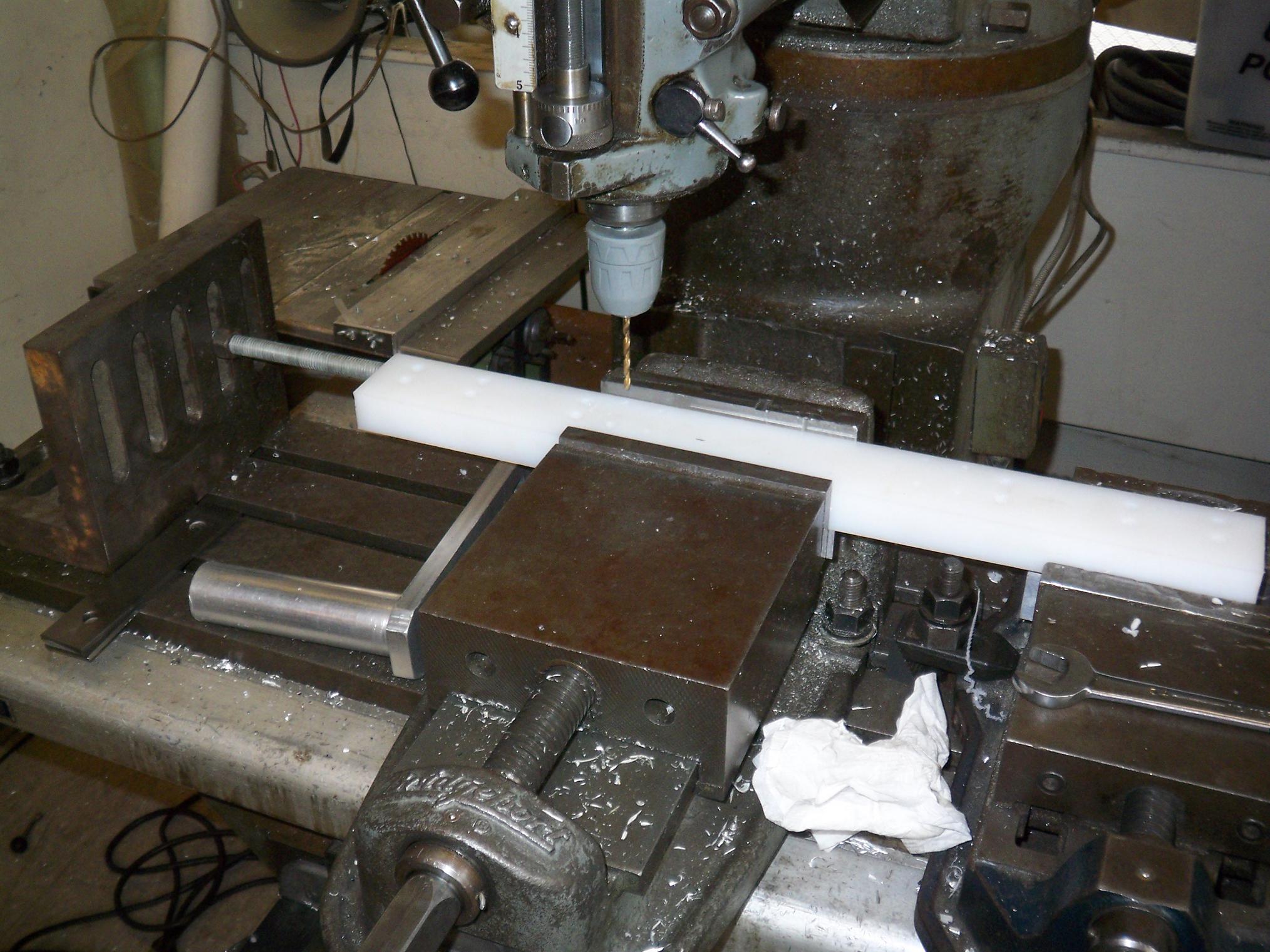
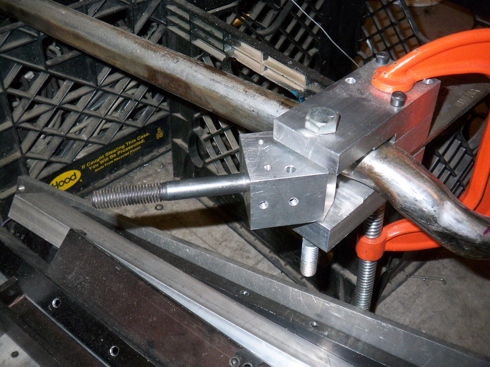
Now moving onto the back end. This is the start of one of the rear axle bearing carriers. There are two on each side, an inner and an outer.

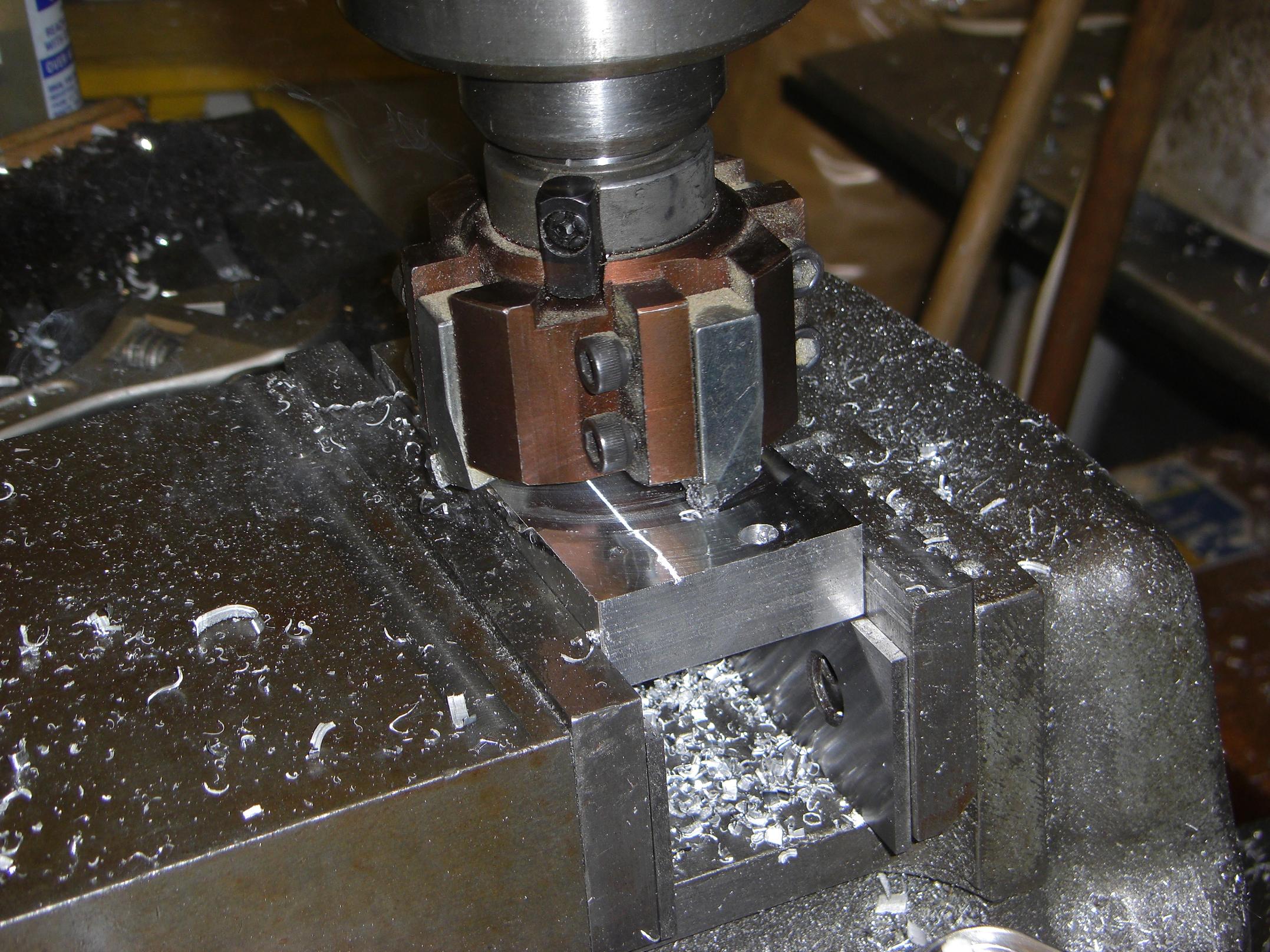
Know what’s really awesome? Obnoxiously large milling tools. I planed across the barstock in one pass with this thing, which seems like a cross between a fly cutter and an indexable carbide mill.

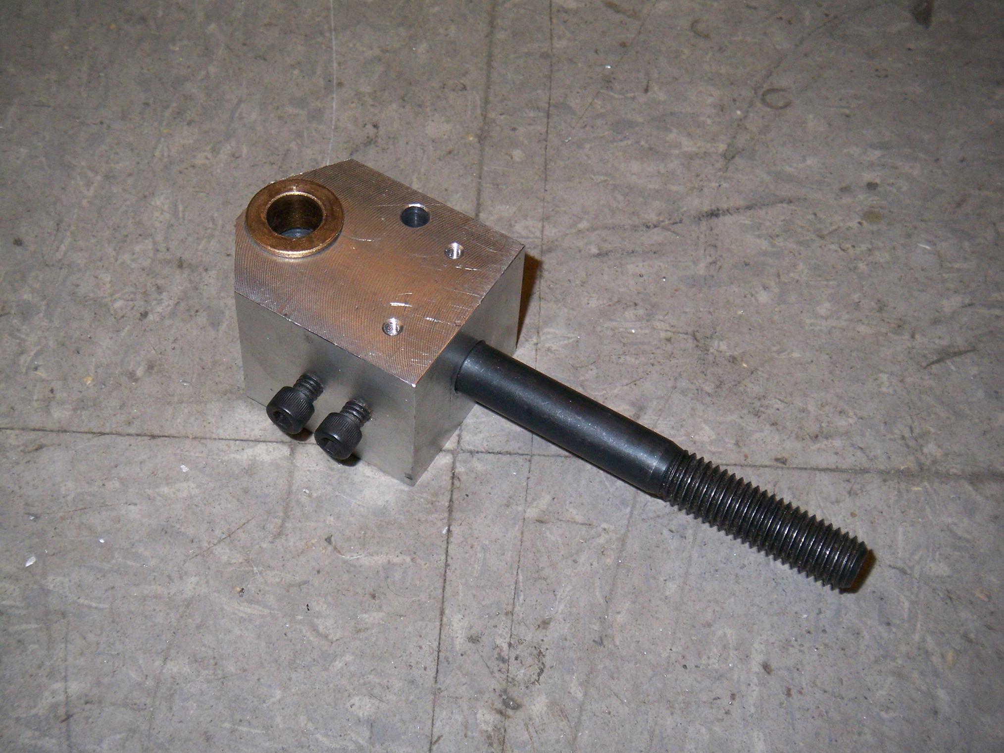
One advantage of having an enourmous cutter is the ability to make angled parts in one pass without fiddling with trigonometry and multiple axis displacements. Here, I’m making a 5.5 degree slope on one of the carriers.

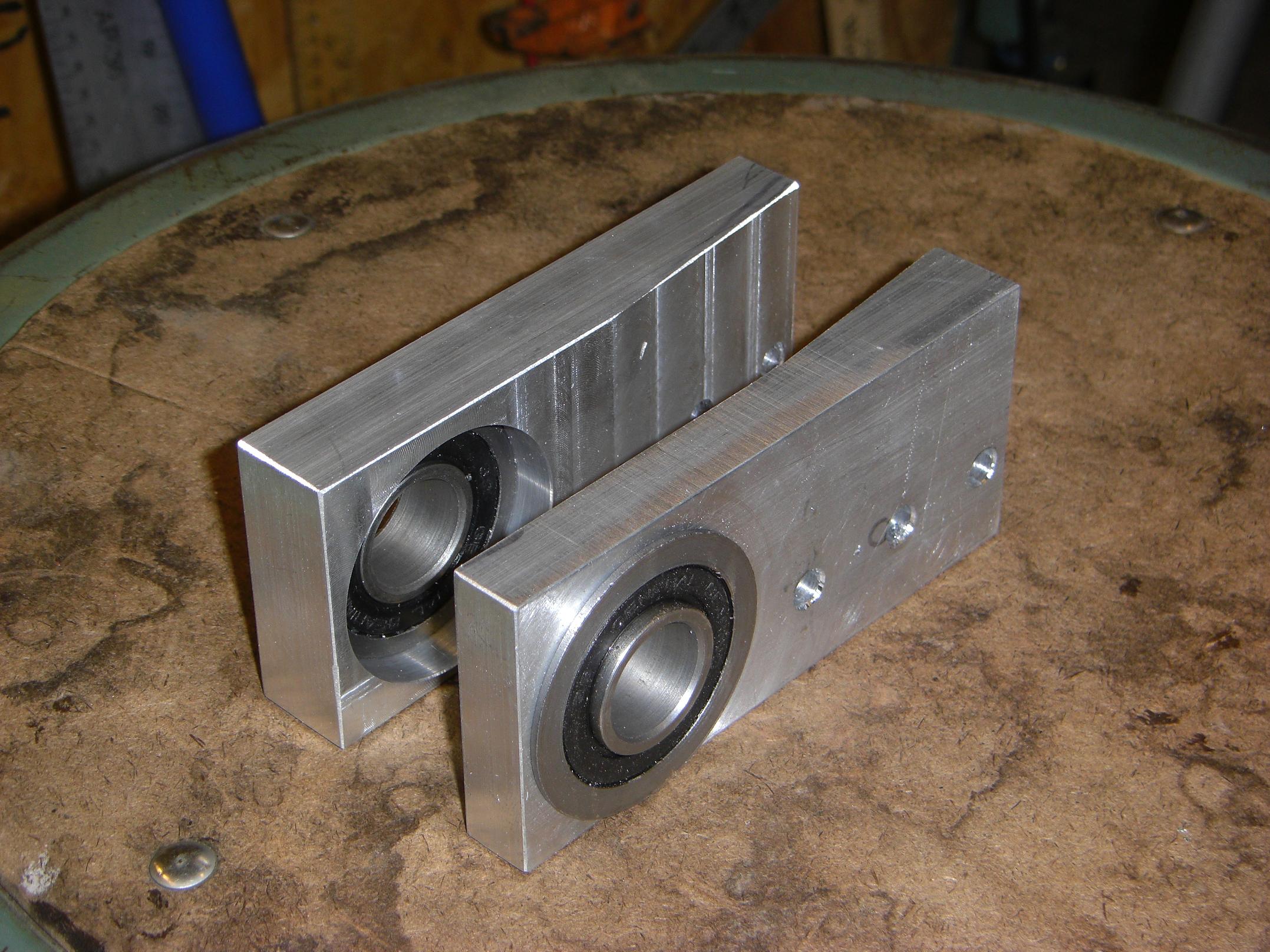
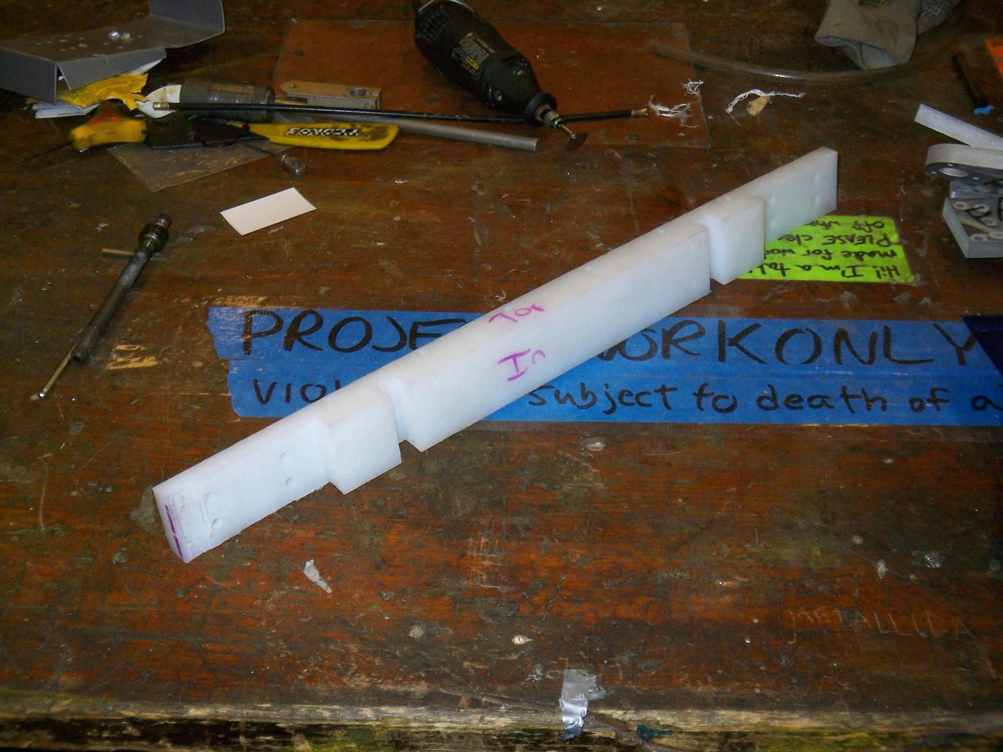
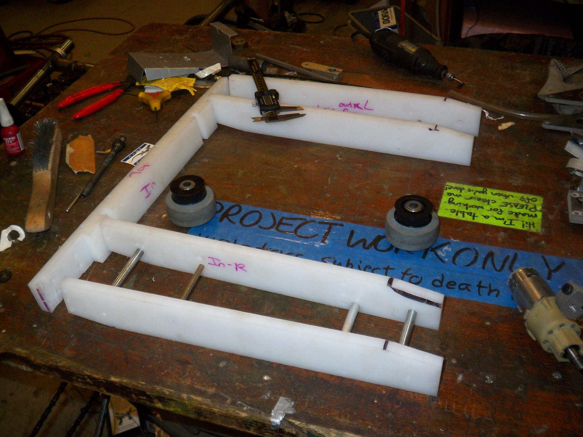
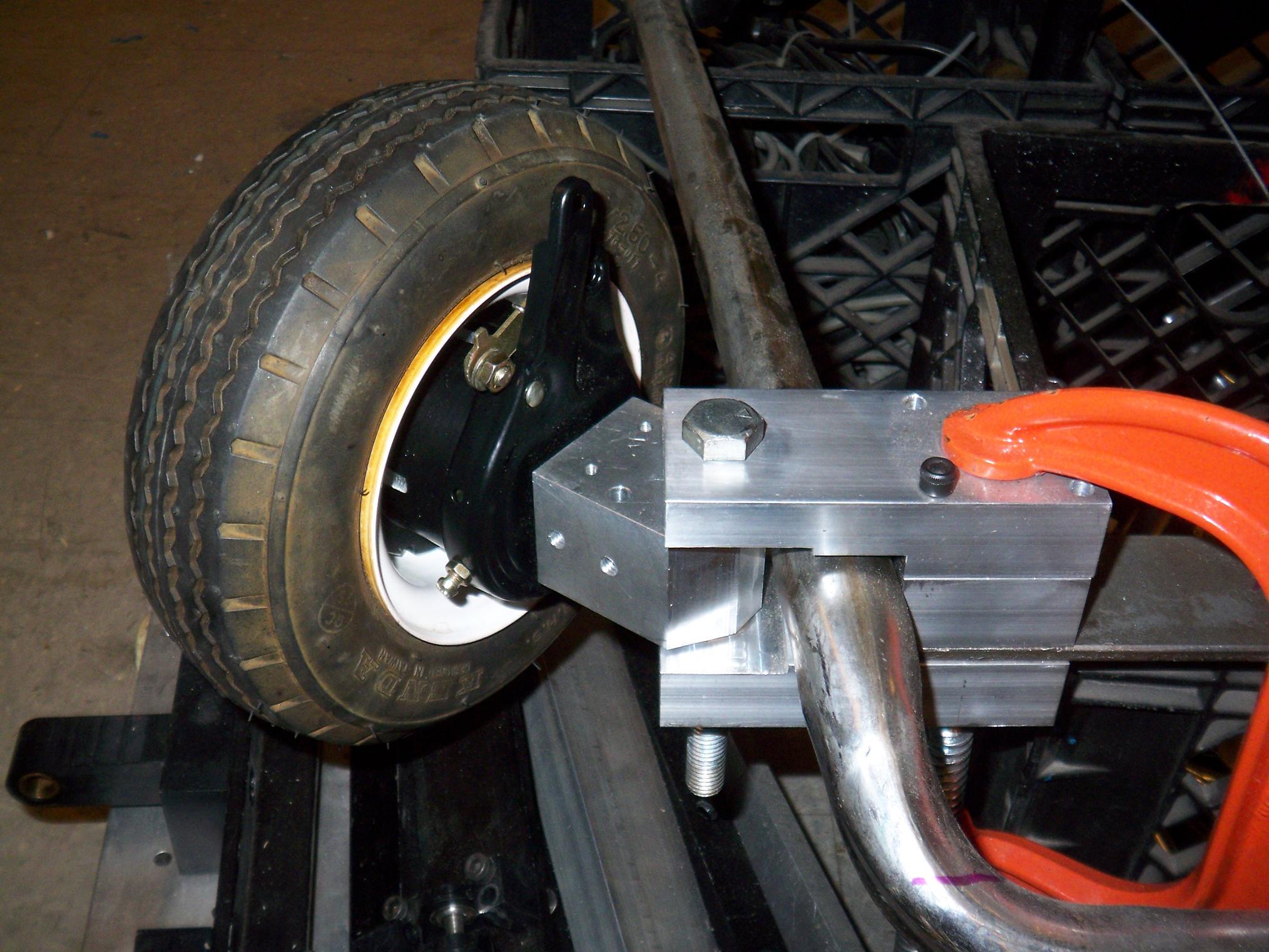
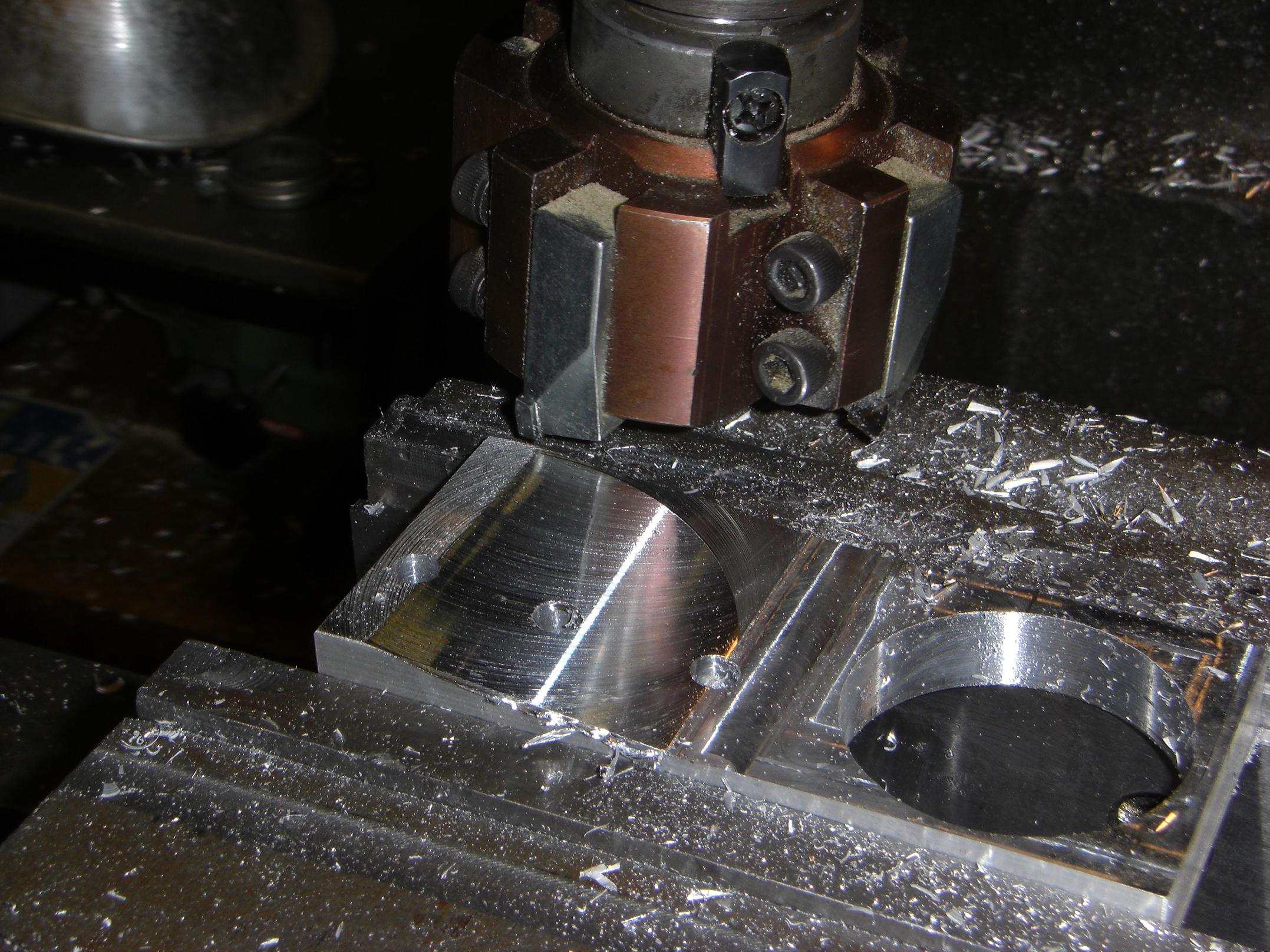
Both bearing carriers. These are both for the right side of the kart. The convex one is the inside and the concave the outside, which the wheel will rest against.

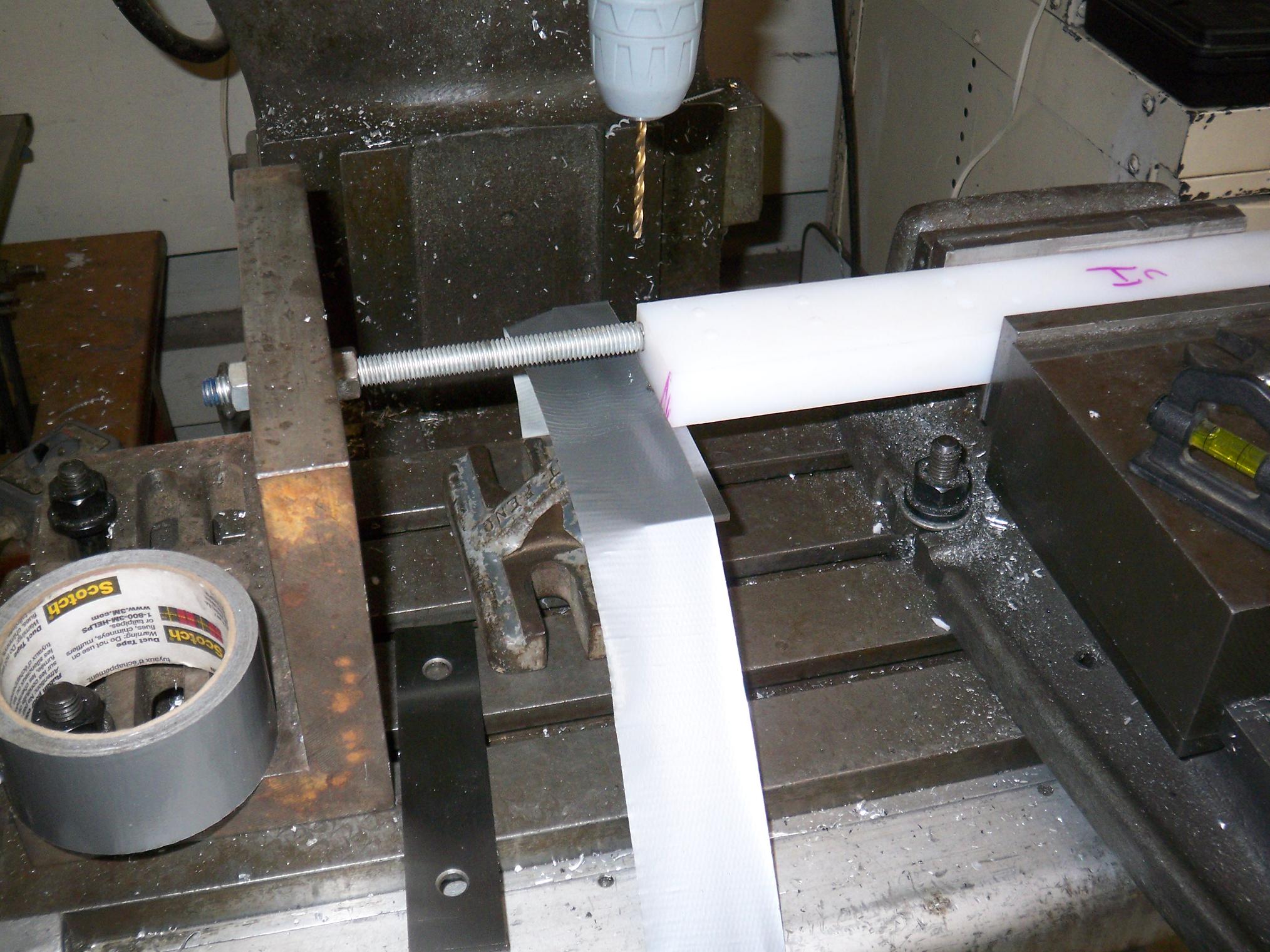
Wait, so, why do they need angles? Shopping carts are narrower in the front than they are in the back. To avoid having an obscene toe angle (and to actually have the ability to drive both wheels with one axle) , I needed to account for this angle. I determined the angle at about 5.5 degrees with a bit of straightedge trickery.

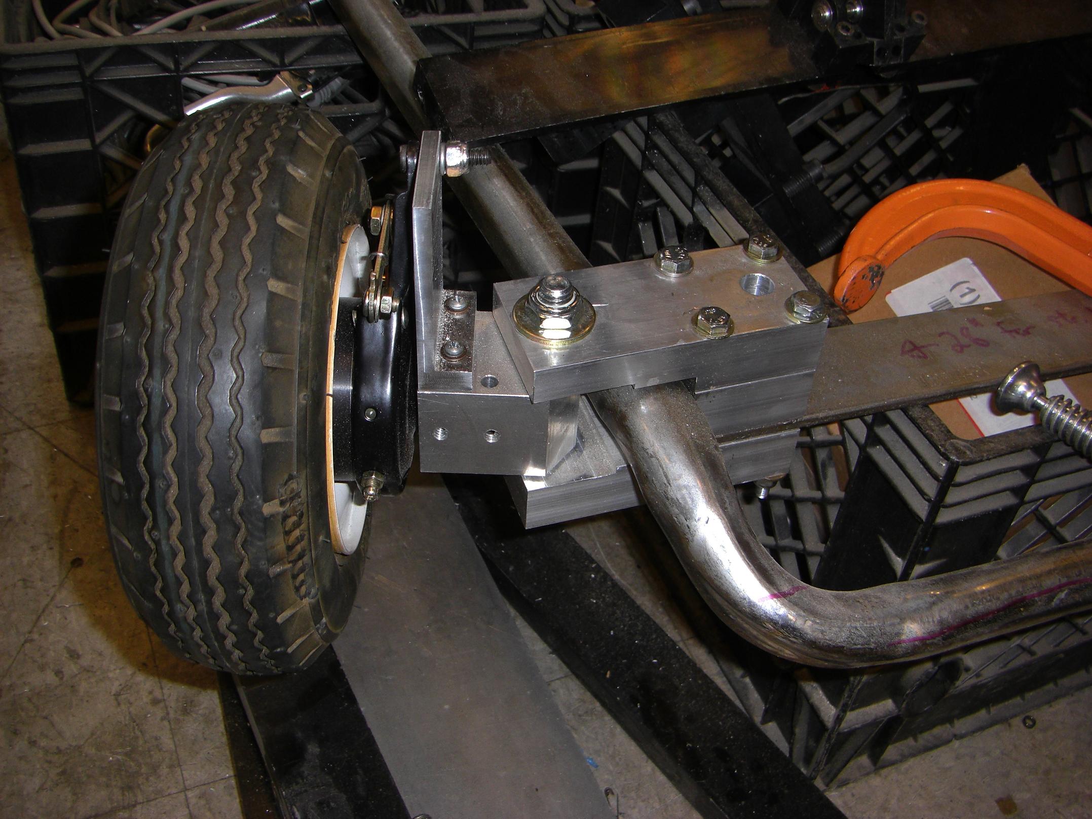
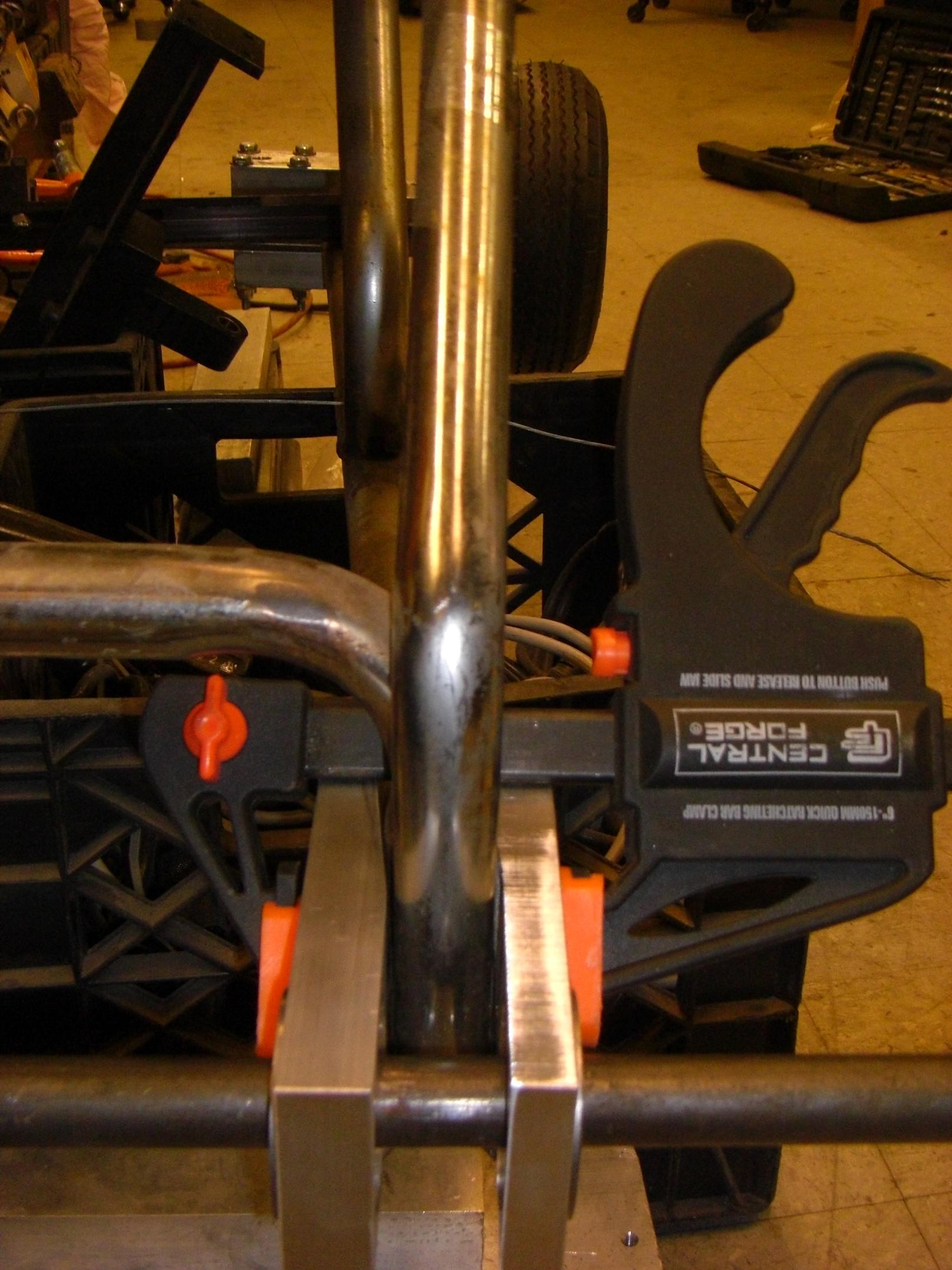
All mounted. I drilled holes through the steel tubing such that I could use bolts to squish the entire assembly together. The bottom caster fork had to be cut off and its former mounting point ground flush with the frame first.

“Drilling holes” was much more difficult than it sounds. Since I was technically drilling at an angle, and with a hand drill, it was hard to aim straight through, and I ended up having to enlarge all the holes anyway. Oh well – noncritical dimension.

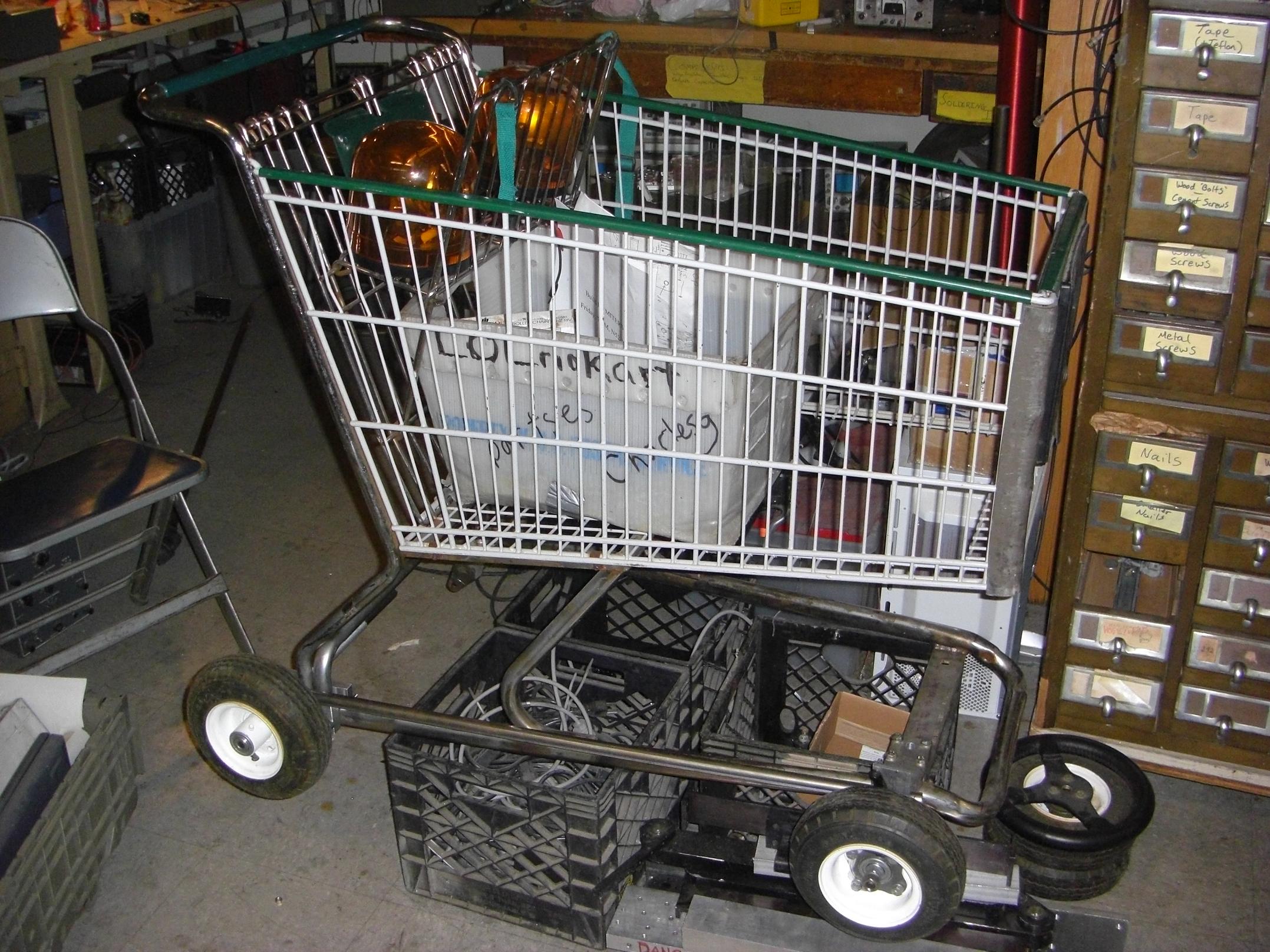
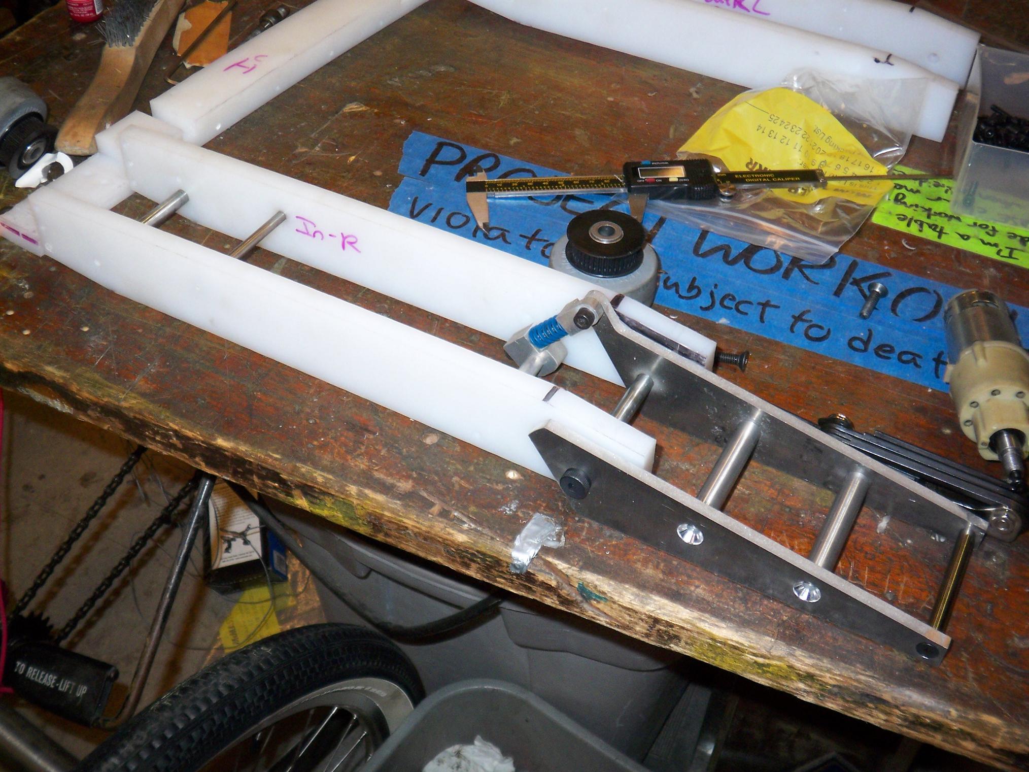
State of the union as of ~9/20.

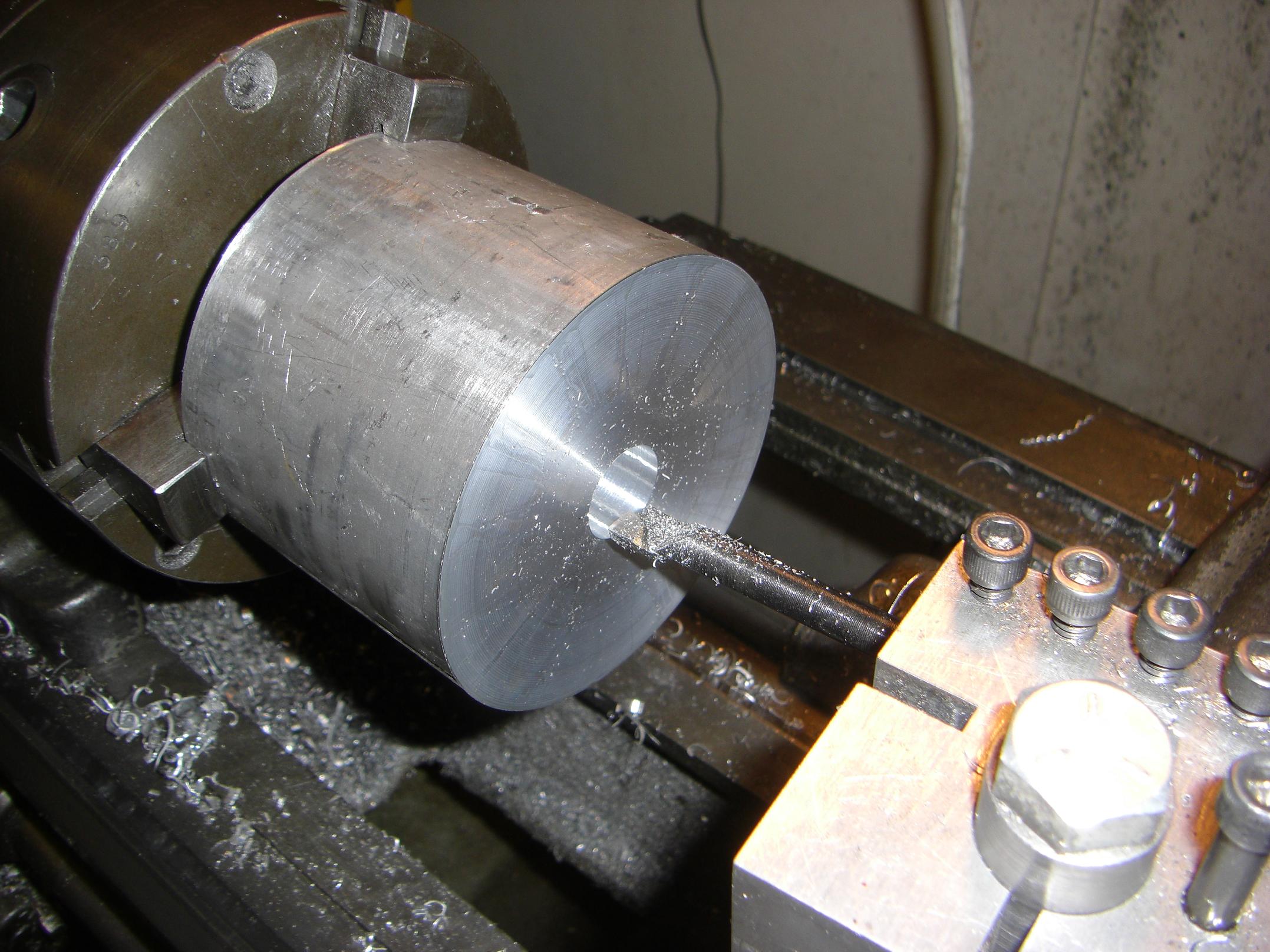
So let’s continue on the back end. I hung this 3.5″ round of aluminum precariously off the end of the chuck in order to carve a drive hub from it. I decided to first bore the axle hole.

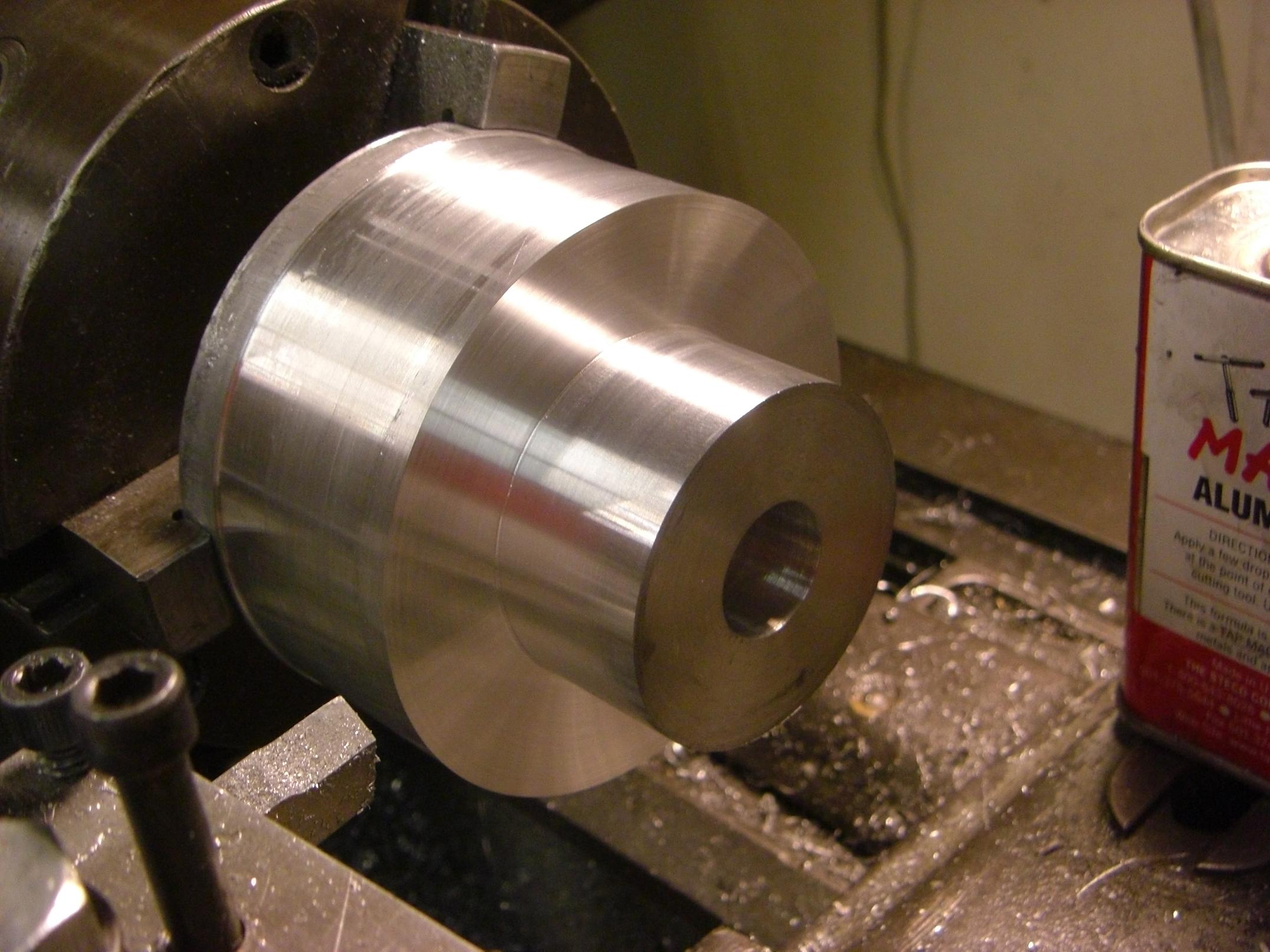
Basic form of the hub emerges from the end of the raw stock. Next was the parting operation, which took no less than 15 minutes, three setup explosions, and an eighth can of Tap Magic Aluminum.

Thus are the perks of having a very old, loose machine and a not-very-stiff tool holding solution working on a hugely huge part. At least the Tap Magic made the space smell pretty.

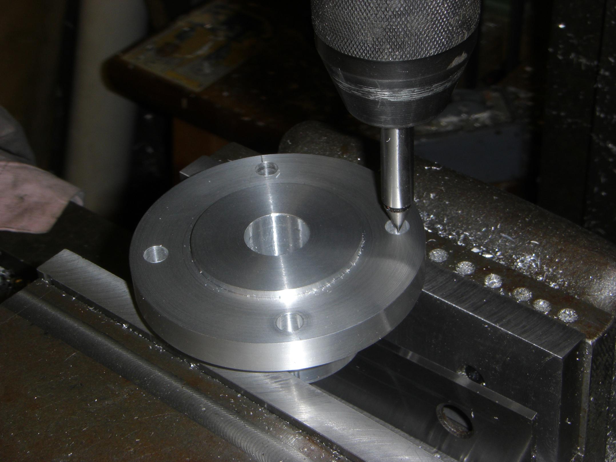
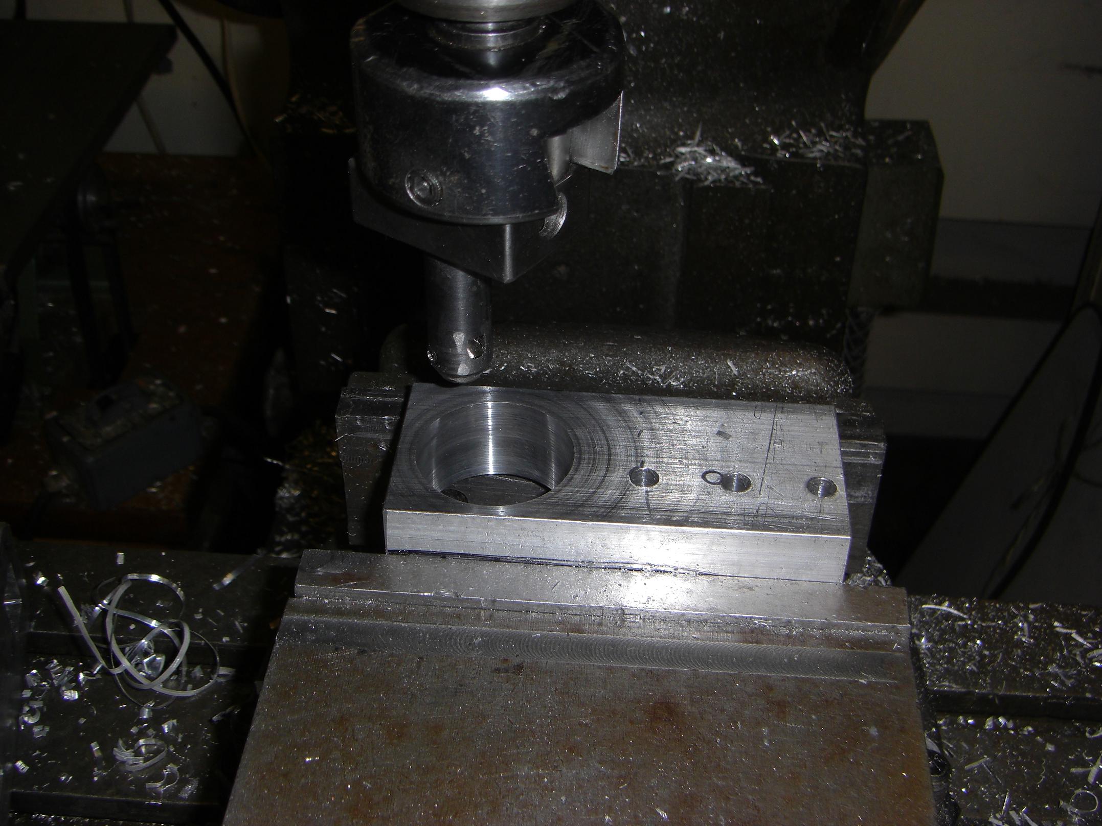
Drilling the bolt circle After I drilled the holes, I realized that the flange was too close to the vise jaws to powertap the holes. I had to remove this setup and elevate the hub with taller parallels.

Of course, doing this made me lose my X-Y position as well as the angular positions of the holes (I didn’t mill any sort of indexing flat beforehand). So, to tap the holes, I had to find their centers individually.

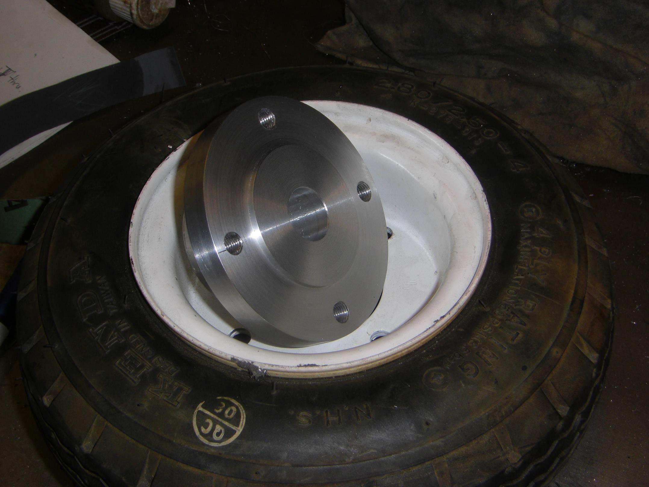
And the mostly finished product. I still lack a power transmission solution for the hub, however – what to do in this case?  My first gut reaction was Enormous Set Screws in the hub, and milled flats on the shaft. But do I *REALLY* want to hold my wheels on with set screws? Should I end-tap the shaft, machine a collar for it, then squish the hub mandrel-style onto it? No, I don’t want an integrated sketch-clutch (sklutch?). The axle is 3/4″ and keyed, so broaching is one option. I have no broach kit, but the student machine shops probably do.

Since I only got a very short section of aluminum, I have to dig another one up to make the other drive hub. How long will that take, I wonder… until next Spring? We’ll see.

Überclocker update 7, LOLriokart update 4

A wonderful weekend of work kicks off with major progress on Überclocker and a bit of work on LOLriokart!

More to come after I wake up at 3PM today…

Übercløcker

The first order of business was to construct the back end of the bot, which acts as the alignment device and reference plane for the entire rest of the bot.

This was a bit of tricky business, since the piece of UHMW is 20 inches long. The Bridgeport mill has…. 20 inches of table travel. A bit problematic. And I only had one non-dysfunctional vise (The other one, shown on the right, is a cast iron Swiss cheese sculpture)

The partstopping angle plate came in handy this time, since it allowed me to shift the UHMW bar left and right to known locations so I didn’t have to edgefind every single time I needed to perform an operation on a section out of reach.

In this episode of Improper Machining Techniques 101, how not to support overhanging work pieces! This is a machine parallel duct taped to a smaller angle plate duct taped to the table, all shoved under the section of UHMW.

This was too sketchy even for me, and so I ended up switching to some of those step clamp blocks. The duct tape couldn’t hold the vibrations of milling slots.

About this time, the Y-axis readout started funking out, losing its value every few passes. This caused a headache really quickly, so I dismantled the slide to find out if something was loose or not.

…. I’m not sure if this is how it’s supposed to be wired, but obviously it’s beyond my level of knowledge. I secured the cable to a similar level of build quality (zip ties!) and tightened the mounting screws (which were loose – likely the source of the issue) and the hiccups stopped.

After some more fiddling with working on a 20 inch part in a 20 inch workspace, here is the completed back rail (without countersunk holes yet). The piece is actually not straight due to UHMW’s tendency to warp while machining (and its naturally warped state). It has a roughly .020″ bow over the longest dimension, which means one side is slightly shorter than the other.

The critical dimensions don’t depend on the actual part height, so it’s not a loss.

Next up were the side rails. To save time and sanity, I set up the angle block as a partstop and clamped all the rails together to be processed (at least, drilled) as one piece.

I decided that this was going a bit too far, since 2 inches of material is alot to ask of any drill bit and totally out of reach of the smaller bits. So I split the rails into left and right sides and proceeded with a setup similar to the picture.

Midway into Saturday evening. All four side rails are processed with the major features (no countersinking or slots, which will come later), so it was time to arrange a test fit & sanity check.

This also included fitting the spring-loaded front support legs and testing them out. Verdict: Pass, but final testing is required. If I ran my calculations correctly, the bot should move over the 1/4-3/8″ floor hazards at Robot Battles with ease, and should balance 30 pounds on the end of the clampfr0k with the springs at full deflection.

I actually managed to lose the other spring, so I’m ordering a handful from McMaster.

After some more hours of work making matching axles and spacers for the newly created left side, it was time for another episode of Pretend-o-bot.

This episode of Pretend-o-bot shows the milled sides and back rail, with the two existing wheels fully mounted and the front supports (mostly) in position. The final bot is taking shape very well. What’s not shown is the almost mirror-like finish of 1500 grit sandpaper on the axle spacers. After all, I can’t photograph through wheels.

I expect some assembly of the frame parts today. Now I’m only waiting on another shot at the waterjet cutter (which may or may not still be mad at me)

Ground clearance check. Chassis: 7/16″ (with baseplate). Front supports: 3/16″. The bottom of the supports might be beveled inwards to allow traversing of the floor hazards.

This is another one of those DUI (Designing Under the Influence, usually of -3 hours of sleep) aspects of the build… why on earth did I make the forks stick out for their entire profile as opposed to only the tip?

What’s left on Überclocker? A bunch of things. All the side rails need their slots and other features to mount the motor. I need to build two more “inner-inner” pieces to hold the back ends of the motors. All countersunk holes need countersinking. The fr0k needs workable parts and final assembly. The fr0k drive needs to be built (actually, it needs to be completely designed first!). I need to make a few more little widgets. Then everything needs assembling.

That’s just the mechanicals.

LOLriokart

Work on LOLriokart Friday evening was focused on overcoming the steering and brake issue. I’m proud (can I really be proud of such an abomination?) to say that this has been solved, so work can shift to the back end to hook up the drivetrain goodies.

Here’s an overview of the progress.

I now have the other half of the steering joint. The assembly is rather simple – a large steel bolt retained by an aluminum block, which has a crossdrilled hole to fit over the steering kingpin.

The additional holes on the front of the pivot block are to mount the actual steering linkages when I get to them.

This is the pivot assembly. The aluminum block has a 1/2″ ID bushing on the top and bottom, and a big 1/2″ cap screw with the head cut off is mounted in a hole. This cap screw will be the front axle stubs, and both the brake and wheel/tire will mount on this.

The cap screw shaft has a big flat machined onto it that is captured by two 1/4″-20 screws. Yes, I’m holding the axle on with set screws.

Famous last words, or a potential Loctite sponsorship?

Wheel mounted for a test fit. These cheap handcart wheels have no internal bearing spacer, unlike roller skate and scooter wheels, so the compression force provided by the axle nuts has to be just right or it will seize. Or wobble. I will probably make an internal spacer to save the trouble.

Front view, showing a profile of the assembly. The Brake-O-Hubâ„¢ extends into the band brake. The brake body itself simply slides over the 1/2″ axle stub, and the arm that sticks out the top will be retained by a bracket to the pivot block. This is why the block has those two little holes on the top surface.

A little spacer keeps the Brake-O-Hubâ„¢ the correct distance from the brake assembly when the axle nuts are tightened.

And in a slightly serendipitous moment, I find that I actually do have an assload of steering travel. I think this is about 35 degrees, and that’s on the more restrained (due to the shape of the cart bottom) side. Looks like the steering arms are going to be pretty long to take advantage of it.

That’s it for now… Work this weekend will probably be concentrated on Überclocker instead of LOLriokart, since I do want to extend my life as long as I can.

Bot on?!