More than a month has passed since the last LOLriokart update. Does it move yet?!
No. I really haven’t had that much time to sit down and perform the design work that is necessary to generate parts. Since I’m practically doing all of this on-the-fly, I need to consider how future parts (i.e. the ones I’m making in 5 minutes) are going to fit with existing ones, and how they might or might not get in the way of things not yet designed.
Now consider that my weekly obligations tend to be sporadic, and that it’s the end of the semester, so everything is coming down to the wire. Throw in a few distractions like finishing the scooter and you get that the plastic milk crates holding up LOLriokart are slowly indenting where they meet the tube frame because it’s been sitting so long. Creep under continuous stress, or something…
But there has been progress made. I’m steadily pushing forward on linking the front wheels together and connecting them to the steering wheel. After that, the intent is to get the front brakes working. Then I’ll have a rolling chassis which can accept whatever powertrain I feel like building.
Here’s the progress over the past few weeks.

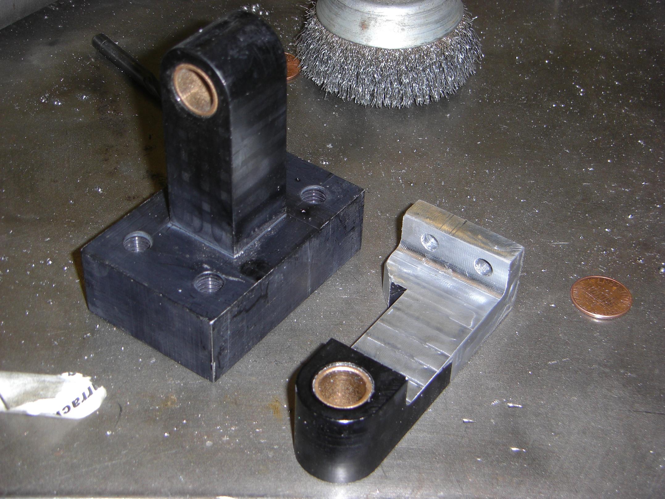
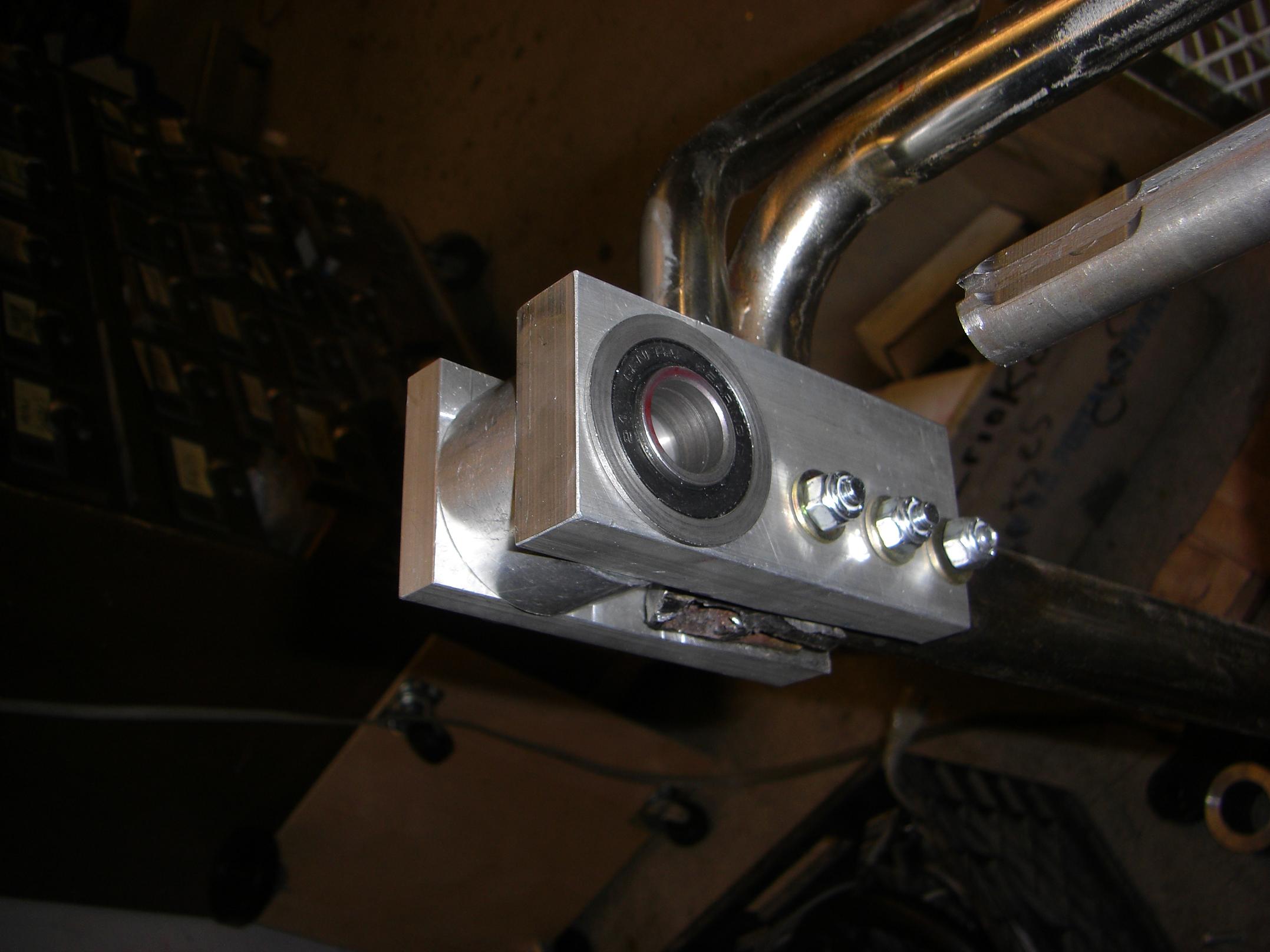
So the steering column will have two segments and three supports. The lower half is vertical, and is supported at its bottom and top by bearing blocks. The bottom support was easy – a bushing mounted to a segment of thick-wall aluminum rectangular tube, which is in turn split-clamp mounted to the original crossbeam which the shopping casters mounted to. This placed the axis of the shaft in a good position close to the front of the basket cutout, which is what I wanted.
The top support for this vertical section was harder. I didn’t have any billet or barstock of the proper size, and I didn’t think the aluminum tubing was going to be sturdy enough given that the wire frame provides no flat mounting surface.
Then Robot Jesus descended from MechE heaven to present me with another near perfect scrounge part. Now I really want to know what this crazy machine that was parted out by MITERS many years ago was – it has saved my ass a few times already.
And so it was that strange trunion-like thing with a 1/2″ Bronze Bushing of Convenience (+1?) only needed about a quarter inch trimmed off the flat side to align the steering column perfectly vertical. It even had large threaded holes on this side to mount on the basket!

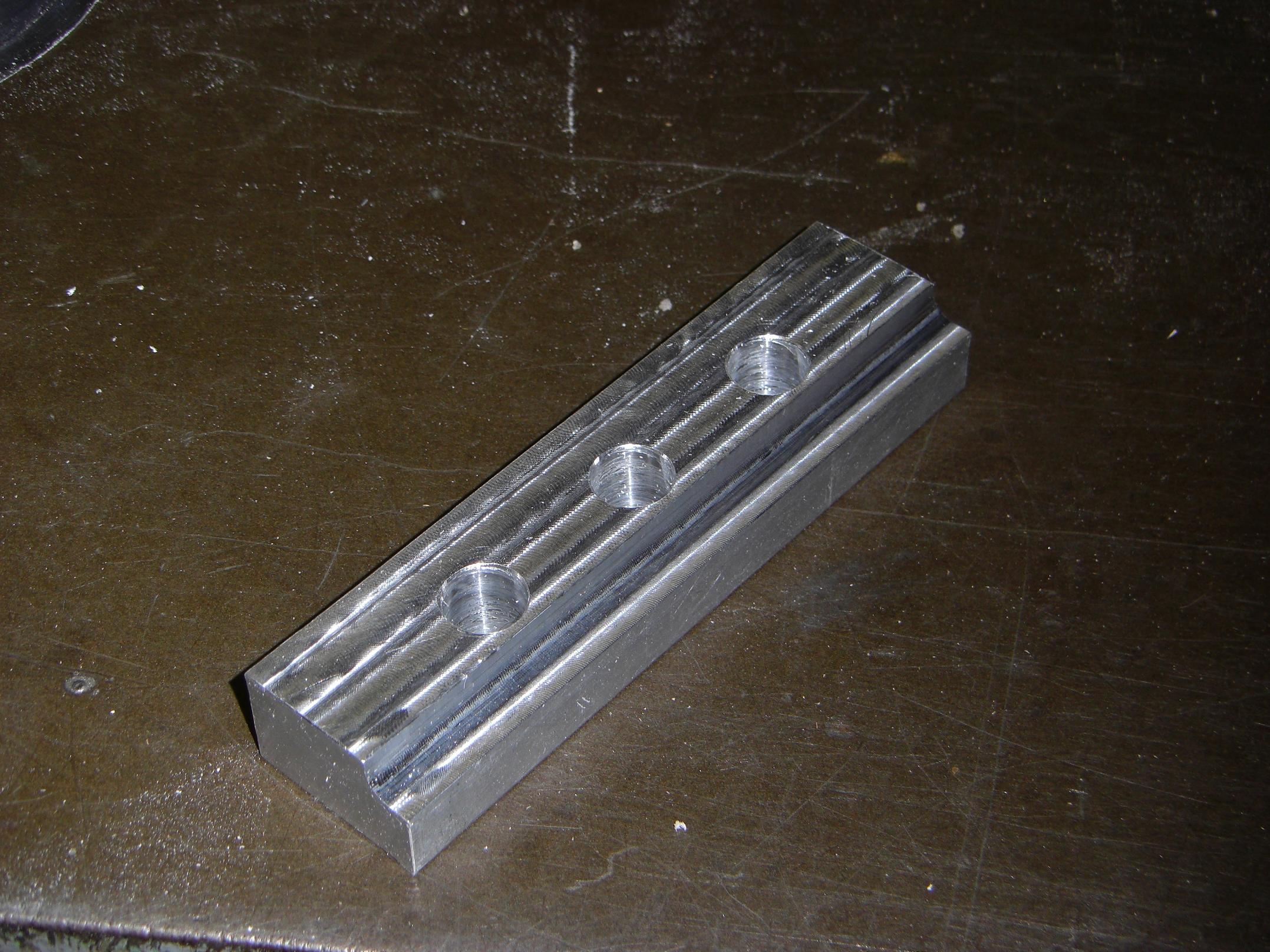
Unfortunately, the front of the basket has an even number of vertical wires. The trunion-thing has an even number of holes. Since the bolts need to pass through the empty spaces between the wires, I wasn’t going to get a centered steering column with the stock trunion. No problem – while set up to take 1/4″ off the top, I drilled new mounting holes right between the existing ones, for three in total.
I also threaded the holes in the same setup, using the mill in low gear (and my big keyless chuck) to powertap the 3/8-16 threads. Apparently, I scare the crap out of everyone who sees me powertap on the mill. But it’s no problem if
- The tap is huge, so it won’t just snap from the torque
- The holder has some sort of clutch effect (clutched tap holders for mills are made especially for this purpose), or is huge enough that anything holding it is going to slip anyway if it is clogged or bottoms out. For more insurance, loosen the belt tension on the motor.
- The quill is allowed to move freely, so the tap can pull itself in and out
- You’re really fast on the motor switch.
With this setup and some mechiprudence, I have powerthreaded holes as small as 1/4″ and as large as 1/2″-13. The latter was pretty ballsy.
So what, I’m not beefy enough to crank large taps…gotta find a solution!
Next was the other side of the assembly.
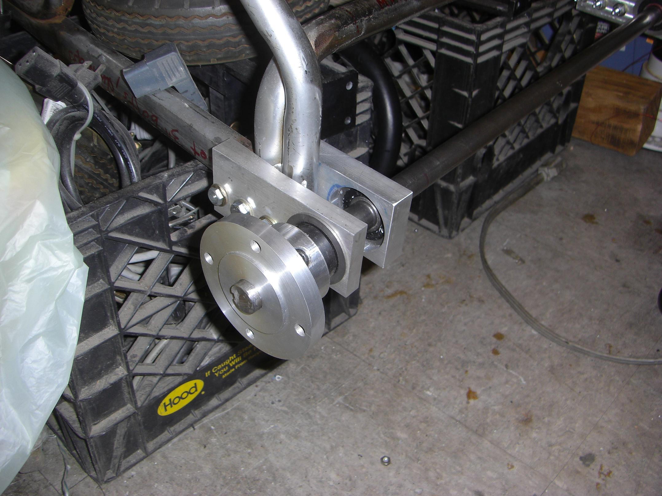
To secure the shaft support from the other side, I quickly cooked up this clamp bar with 3/8″ through-holes.

Whole assembly fitted. The little rounded cutout on one edge is to hang onto one of the horizontal wires to keep everything more steady. It was made using a radius-tip (not ball-tip, just radiused) cutter that I got in a toolpile from Ebay.
This is yet another extremely overbuilt impromptu part that should never fail. If it does, I’m probably spread into a very fine film already, and thus would not have to worry about repairing it. Other parts of this nature on LOLriokart include the steering brackets, rear bearing blocks, wheel hub and mounts, and… oh, wait.
I love billet aluminum.

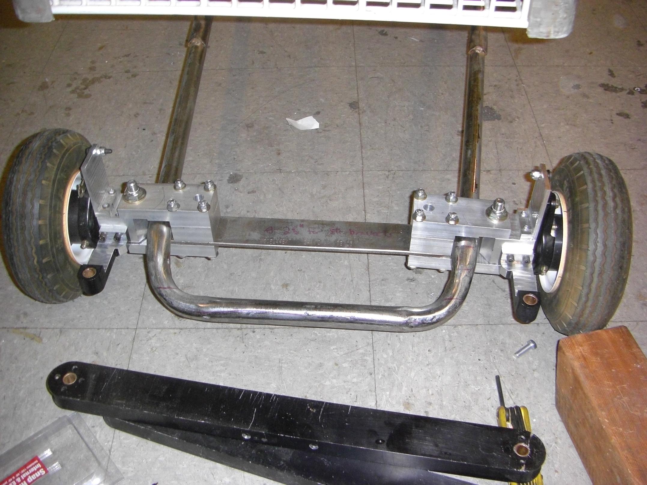
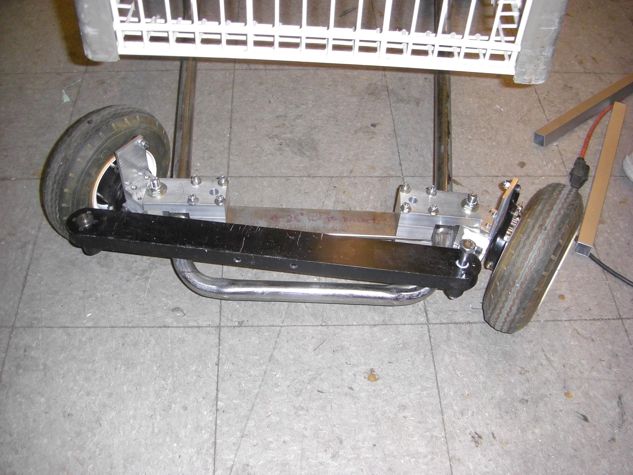
Let’s move onto the steering linkages. While the big aluminum tube acting as the steering tie link was nice, it’s just too bulky. I came up with a new plan involving ball joints (or “rod end bearings”) and threaded rods.
A large threaded rod connects ball joints at both ends of the tie link assembly to a rigid center piece which mates with the eventual Pitman link (that in turn is rigidly mounted to the steering column). The ball joints go to the steering links on the front wheels.
It was Thursday night, and if I ordered ball joints from McMaster, they’d ship Friday morning, get here Friday evening, and be stuck at Shipping & Receiving all weekend. I don’t have the patience for that kind of stuff, so I just rolled (milled?) my own rod ends. Fortunately, the Media Lab guys bought a basketfull of ball joint bearings for the car project a while back, and ended up using a handful. I nipped two and carved some aluminum holders.

Installed. There’s a 1/2″-13 hole on the back side to accept the threaded rod, which I manually tapped this time. It was a great exercise in how to start a giant tap straight, and just great exercise in general.
I ended up using two steel pipe sections, 18″ long, as handle extensions on the tap wrench to give me more leverage.

Assembled. The ball joint gives about 10 degrees of tilt and roll in the steering linkage. I won’t need this, but it was nice to have, since I’m sure nothing is actually aligned properly.
Normal people would have welded all of this up and have been done in a day. I, however, have a disdain for welding because it’s just too permanent. Yeah, no such thing, right? I like having the ability to take my stuff apart. This will all come apart into neat aluminum billet pieces when I’m done – not ugly, globby things I have to hack off with a grinder.
Let’s hope it doesn’t come apart into neat aluminum billet pieces while I’m driving it. Maybe that’s why we weld…

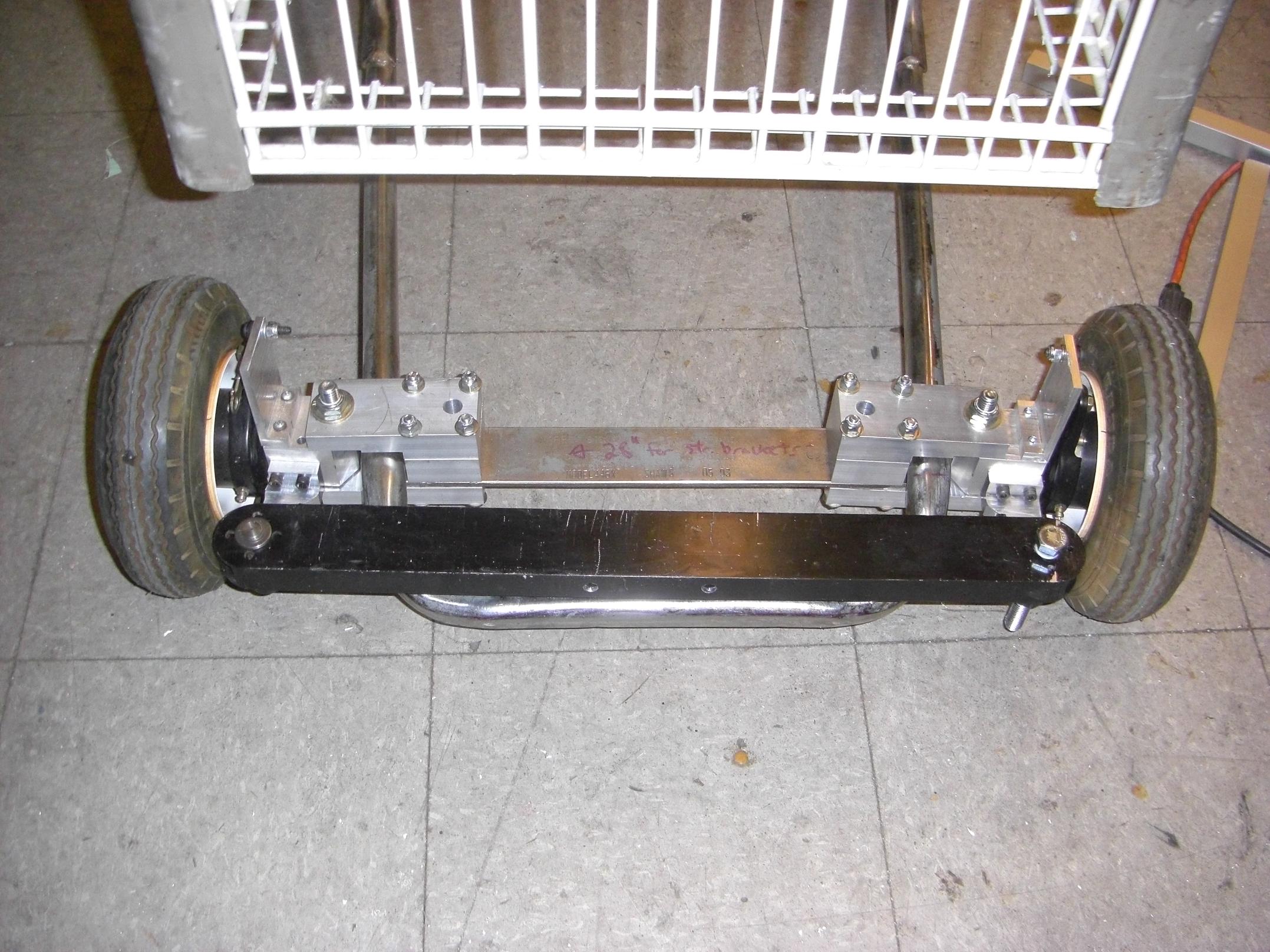
I suddenly had a change of plans while building the linkage ends. Instead of using a single threaded rod, I could use two separate ones, and have the ability to tune the toe angle by moving the rods in and out and locking them in different places. Even better, why not use some big Grade-8 cap screws?
So the plan then became using the rigid center piece as a bridge between the two cap screws, using a clamp-mount type assembly at both ends to hold the cap screws right behind their heads. Thus, if I needed to tune the toe angle, I could loosen the clamp, turn the screws a bit, then lock them back down.
This meant I had to make the aforementioned rigid center piece longer than if I had just ran a threaded rod all the way through, which means I have to go buy more bar stock since it exceeded what I had available by a factor of 2. Effective use of available materials, people!
Or maybe I should go find cap screws 1.5 times as long?

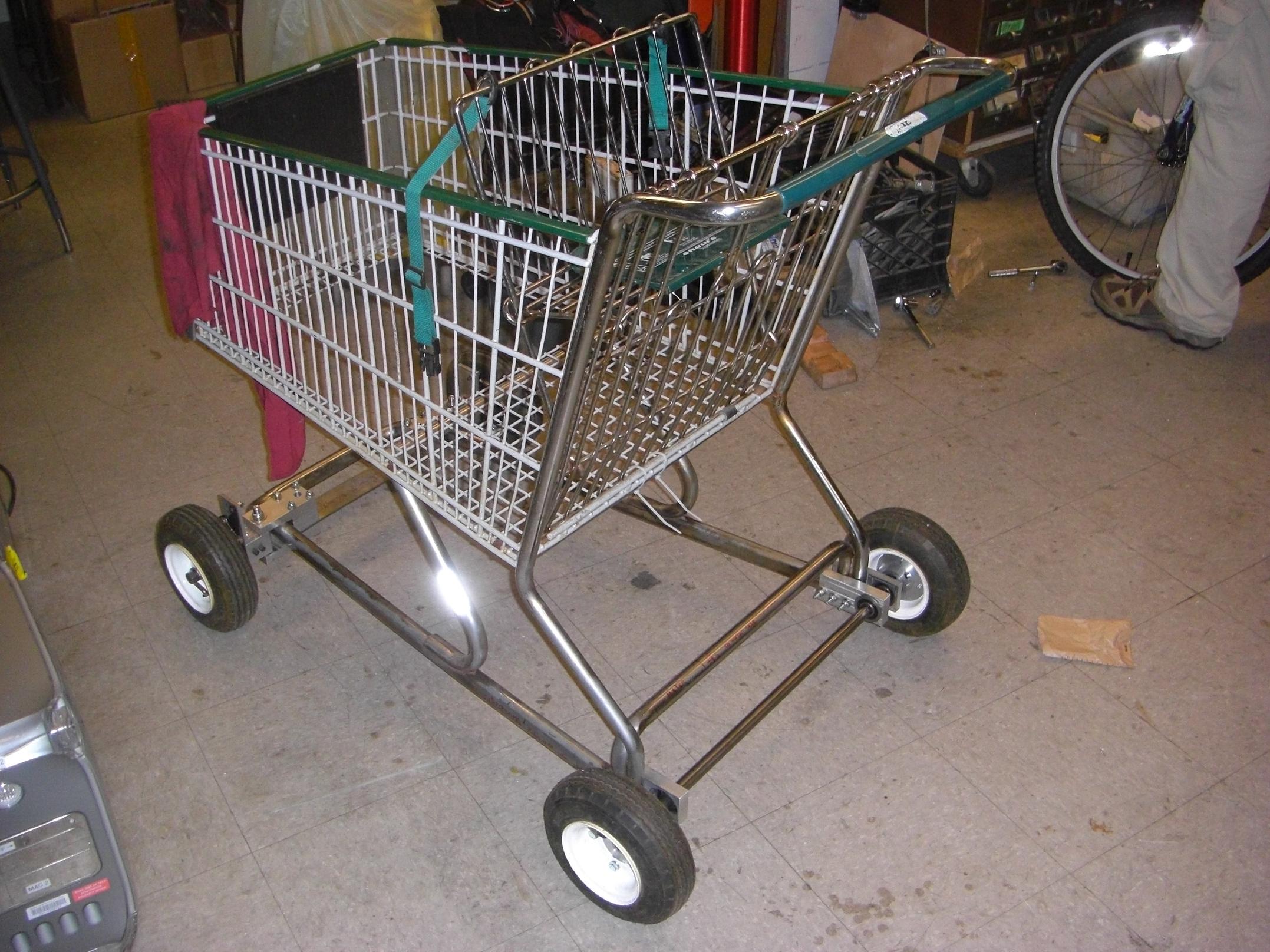
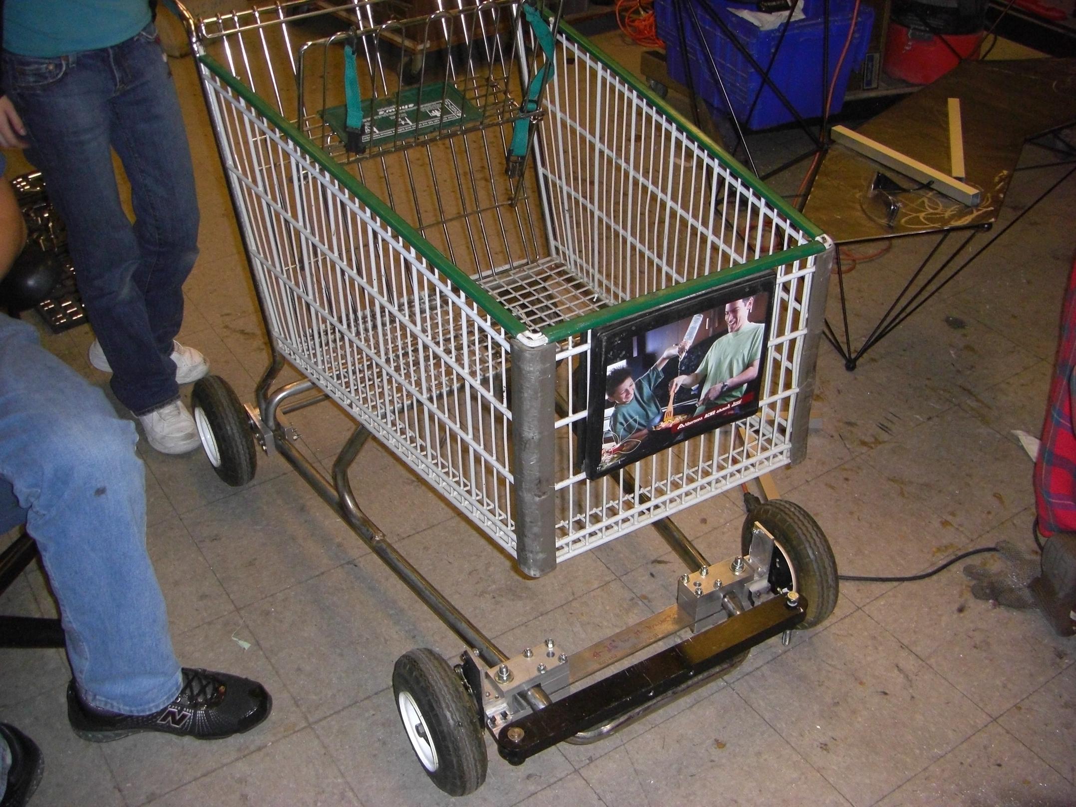
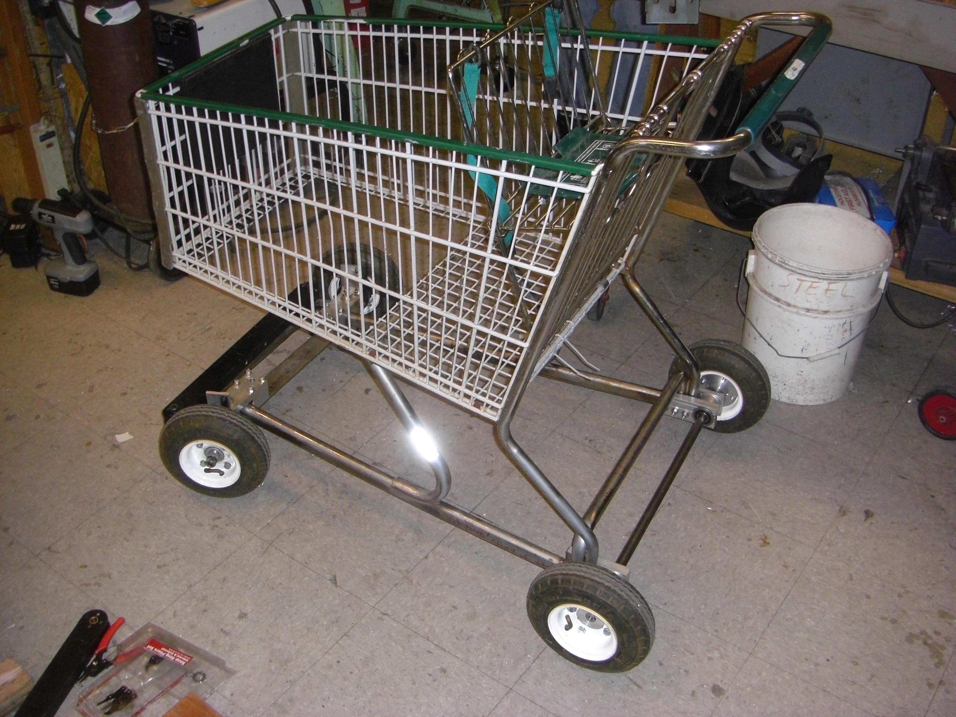
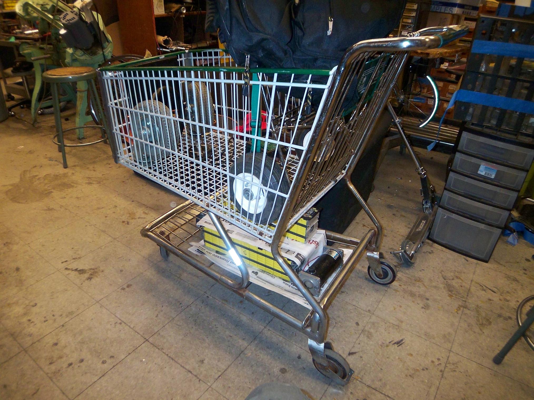
Alright, enough fun for now. This is LOLriokart as of two days ago. It has clearly evolved from a shopping cart full of shit to a slightly more fancy shopping cart full of even more shit.
Ah, but useful shit.
This is probably all that will happen until I return from Atlanta for the remainder of IAP. However, I can still work on modules and parts while I’m in Atlanta – just won’t have the opportunity of knowing I’m doing something totally wrong mid-process.
One assembly that I intend to make in Atlanta which will make the project that much better, is a rear differential. As long as I’m not building a wheelmotor for each wheel (Hey, maybe that will happen in the future) and it only has rear wheel drive, then I should probably add a differential to the axle. Otherwise, the two rear wheels will try to rotate the same speed through a turn, which as anyone familiar with vehicle dynamics would know, is…bad.
I’ve sort of held off on this for a while, since getting the solid axle version running was a priority, but as long as I’m taking this long on everything, I might as well. Here’s the plan.


Wait… What the balls is that? That doesn’t look like a differential! There’s not a single bevel gear! This looks like a differential.
Correct. This is a design known as a planetary differential or a spur differential. It uses the principle that two mating spur gears rotate in opposite directions to produce the same action that a set of bevel gears does.
The two output gears are separated by a gap. Each output gear mates with a small, long pinion (longer than its diameter, such that it bridges the gap, but stops just short of touching the opposite output gear). The long pinion of each output gear in turn mate with eachother in the gap.
Result? Let’s rotate one output gear clockwise. Its long pinions will rotate counterclockwise. It mates with the long pinion of the other output gear, rotating it clockwise. In turn, the other output gear rotates counterclockwise, the opposite of the first. This is the same action that bevel gears provide when put into the classic box arrangement seen in open differentials. You may multiply the number of long pinion sets around the perimeter at will to get more strength.
Using helical gears and a slightly different arrangement gets you the Torsen type limited-slip differential. That’s an exercise for another day.
Benefits: No weird (expensive) gears. No weird geometries to machine. Can be made using standoffs, bolts, and stock gears. That’s what I intend to do. Except just big, so it can take the torque of the Etek.
Speaking of what the balls, I also drew up plans for a giant ball differential (as seen in R/C models) a while back, but at this scale, the design will be very inefficient.
Onwards!!

