Oh, Brushless Rage… how far you’ve fallen. It’s been standing idle since late last year when I got the first version running. Thereafter, it began having some rather obdurate power supply problems that I couldn’t resolve with a few different attempts, and with #season3 still unknown (TO. THIS. DAY. UUUUUUGGGGGGGGGGGH.) and having to pick up and move shops, I lost motivation. Now, with the spring and summer silly go-kart season coming up, me really wanting to pregame getting Overhaul back in shape ( *cries deeply* ), and my comrades over at Robot Wars screaming for assistance, it’s time to put my robes and wizard hat again.
The last time I really worked on Brushless Rage was in October. After tuning out the first one, I went ahead and made a 2nd one. I wanted to get Sadbot running on them for a few test drives.

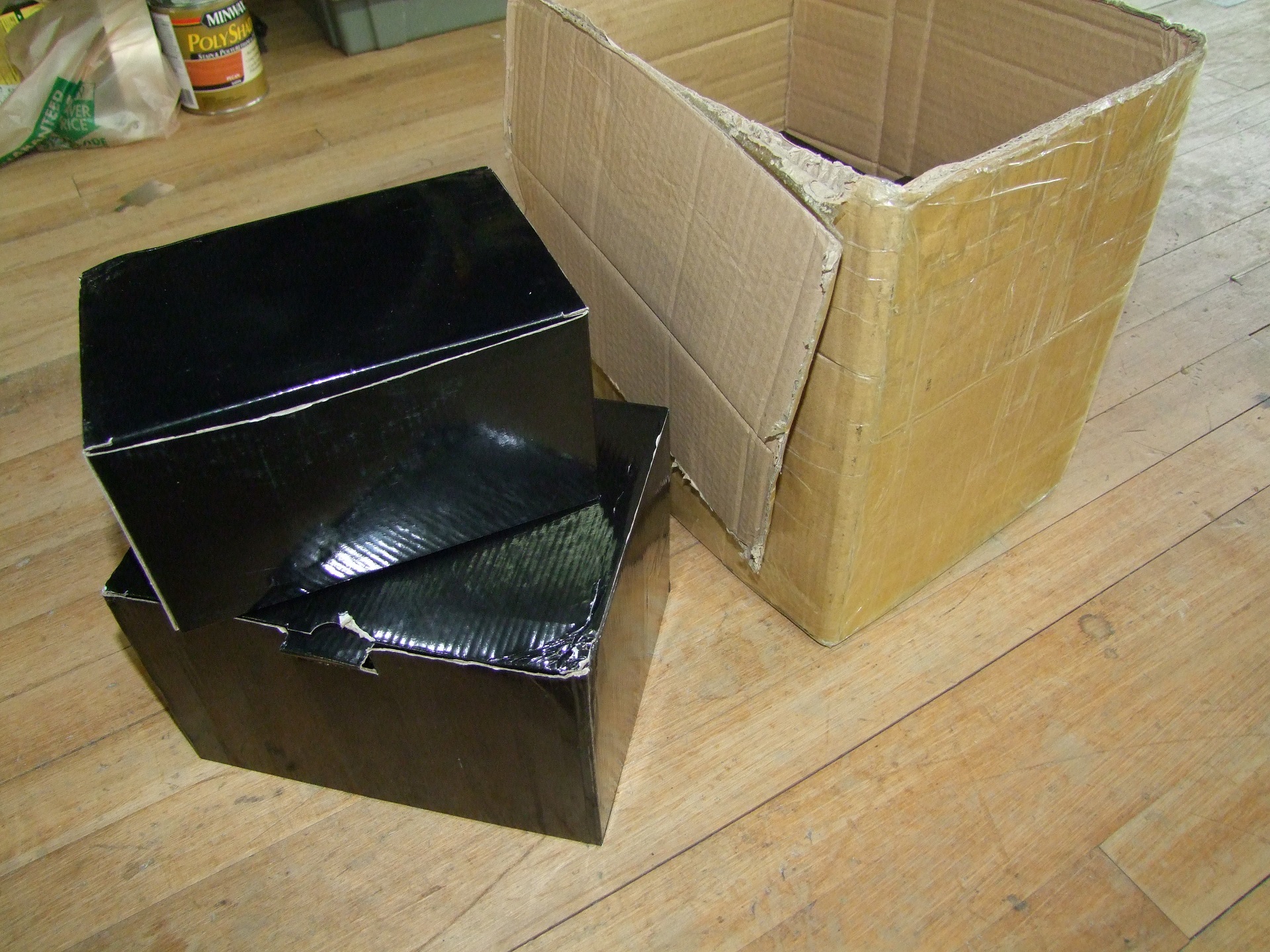
Here’s my innovative housing for the two controller! Bolted back-to-back with drilled holes in the Ragebridge shipping box.

And that was all! It was retained by a few zip ties running through the bottom ‘breadboard’ baseplate. I didn’t take much test video of Sadbot running on them, unfortunately;really the only one that exists within easy reach is, uhh, this one. While it doesn’t show them getting whipped, they definitely don’t not work! Yay!
But not for long. I soon lost both of the units in further off-bot tuning of settings. They didn’t blow up, but simply failed to ever power on, with the LM5017 regulator simply sitting there getting hot. The only “fix” was replacing the regulator, and I say “fix” because that really didn’t fix anything, and they would die again within minutes or even seconds.
No problem… maybe it’s just an issue with the two boards. I’ll just try another one of the five total I ended up making….

Nope. Nothing. They died one by one, all to the same symptom. I tried redoing my math for the regulator for the 4th time, thinking maybe I made a mistake somewhere. I even tried mimicking the reference design to try and get something running. I literally never do that.
At this point, I figured it must have been something incredibly dumb and simple I missed. But why would the first two have worked at all, even for a little while?! Convinced the solution might just suddenly invent itself, I stopped thinking about it.

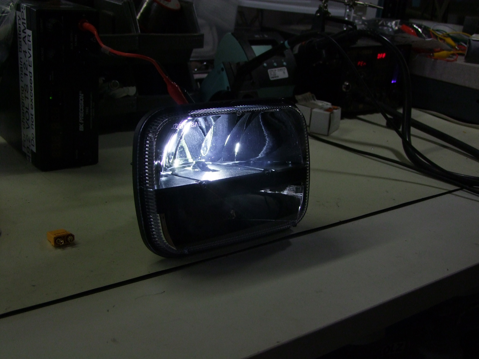
And so here we are, a few weeks ago, when I’m slowly building up a new rev of the logic board that fixes up some trace routing problems and Little Blue Wire problems. Again, the logic regulators kept exploding, some times dramatically taking out the input trace like seen above. The little light is strapped across the 15V gate drive supply to give me a visual indication of it being on.
What is with me and being unable to use switching regulators!? I recalled the Ragebridge Diode Debacle of 2015, and decided to take one last Hail Mary run through the datasheet along with friends to carefully cross-check each other for boneheaded mistakes and…….

TI, you assholes.
So here’s what’s going on. The Vcc pin of this chip allows you to power it from its own output voltage, which is often fairly low, so it prevents a lot of heat dissipation in the chip since otherwise it would have to derive its own power from the voltage input (up to 95V). But what I missed is this only works up to 13 volts. My gate drive supplies were 15 volts by design.
Beyond that? Who knows?! It might work, it might not. I’m guessing my first two were just high enough in manufacturing overhead that they worked for a little while. Subsequent statistics were not on my side.
Okay, whatever. I cut off the 11.3kohm feedback resistor and threw on a 9.1kohm to drop the voltage from 15V to about 12.5V and let’s see what happens.

Ah, it wakes right up.
Of course it does.
So I decided to respec the gate drive for 12.5V. Why do this instead of go for the full 15+ volts? Because I’m really aiming to make this design work at high-for-robots voltages of 36-48v, possibly up to 60V nominal with a different power stage, so I’d like to save the power dissipation in the chip’s onboard logic power supply.
The change in drive voltage will slightly affect the drive characteristics and switching time. For now, I’ll keep all the power stage parts unchanged, but I’ll probably tune the gate resistor values later.

To get rid of the noisy ripples on the feedback network and to stabilize the switching frequency, I added some more bypass capacitance to the chip. This was not included in the design at first, since I figured my large ceramic input and output caps were nearby, but it really really wants its own little private capacitor on Vcc. Gee, I thought I was a princess at times.
So now this thing is pretty much bombproof. Here’s a video of it throwing around one of the 30-pound old MIT CityCar prototype motors (which I inherited 4 of after the project was dismantled):
In that video, it’s running from 36 volts. I tested it with a smaller motor all the way up to 50V input before getting too scared for my power supply’s life; I’ll need to try it on a larger high-for-robots voltage power system later, but nothing smelled imminently unhappy!
With the regulator death issue apparently behind me (again) I decided to push another board revision. This time, I added all the necessary bypass caps and changed the layout of the logic power supply, as well as take out some parts I decided were superfluous.

The logic power supply got a little smaller and more electrically optimal. The whole thing is just less messy now. I like it – it takes up around 1/3rd square inch of PCB space on one side. At the behest of a professional PCB engineer friend, I turned the inductor 90 degrees and joined it with the LM5017’s switching node with a small trace instead of a larger groundplane. This would prevent the switching node (a source of huge voltage swings in microsecond timescales) from broadcasting as much noise.
Besides some other minor trace chasing, what’s going on down below on the board is also something experimental:

That there is a bidirectional optoisoated I2C bus for transmitting data between two microcontrollers which should never meet directly. I had a single-direction opto input on the board revisions so far, but this prevents updating of settings via the SimonK/BLHeli type bootloaders. That means tuning the settings require busting out my chip socket every time, which is annoying. I reviewed a couple of bidirectionally isolated bus schematics and decided to try this one out first, since it involved diodes only, not transistors.
The problem is, the I2C bus is a open-drain configuration with pullup resistors and ‘1’ bits transmitted by pulling the line down to 0v. I kind of wanted to try keeping the opposite polarity, so to speak (even though SimonK supports an inverted input setting) just because I’m used to thinking about things this way. So I tried flipping the circuit over…. pullup resistors became pulldowns, and common-emitter became common-collector, and so on.

It makes sense in my head, but I’m sure excited to see this work!

On the board, this is the layout. It doesn’t consume much more space than my previous 1-direction optocoupler setup, and can be bypassed for testing with 2 wires if needed. That’s the nice thing about keeping things upright signal-wise.
So before I sent this board revision out, I stopped for a moment to think who would really be wanting to use Brushless Rage. I’d designed the 12-FET board to effectively replace Overhaul’s 250A DLUX controllers (with more realistic ratings, mind you). I’d say the majority of people who would buy such a thing won’t be running motors that big.
Recently, the thought of a “Half-Rage” has been coming up in my mind as something worth pursuing. This would be a board with about half the footprint of a RageBridge 2 and supporting about 1/2 of the amperage. As some curious question-askers had innocently drilled into my mind, this would be an Actually More 30lber-Sized controller.

> mfw "When are you going to make a 30lber/12lber version of RageBridge?
With this in mind, I decided to make a copy of the power stage and began downsizing the hell out of it.

Step 1: Reap what I sow when it comes to the sheer number of vias I deposited under the FETs.

After bunching the FETs together, I referenced one of the earlier abandoned Brushless Rage layout ideas for the output wires. This board is now short enough that I’m comfortable pulling the phase outputs all the way to the right with the power. Keeping all my wires on one side is something I prefer.

Somewhat final routing of the fat bus traces here. I had to move a few gate drive traces, as there was no longer an opportunity to swap sides in the middle of the FET bank. Power+ runs straight from the bottom right corner, through the bus capacitors, into the high-side FET. Power- emerges from the current shunts and then has 3 paths to return to the buscaps before being slurped up by by the wire hole on the upper right.

Here’s an overlay of the signal board design on the power stage, showing roughly the size of things. The final power stage is 2″ x 2.75″. Not the tiniest thing, but I have more capacitors than you!
This board shares a lot of thermal characteristics with RageBridge, so I’m pretty comfortable calling this a 50A continuous class controller. 50 real under-partial-throttle amps, so that’s what, like 1,200 Hobbyking Amps?
In all likelihood, this controller will be able to handle an average 63mm SK3 motor in continuous duty applications like a silly go-kart. Robot-wise, it will probably be stressed handling the same in bidirectional drive mode.
Fast forward a few days and….

OhmygoditssocuteIjustwanttohugit and then make it run a 80mm outrunner on 12S violently. I’ve ordered parts to make a handful of these, and two are going on Sadbot ASAP to be driven until something blows up!
Direct Outrunner Hub Drive for Your Little Bot
Next up, something even smaller!
So I’ve long been a connoisseur of fine handcrafted hub motors. I got curious recently on using direct-drive small outrunner motors in an ant or beetle after thinking a while on the redesign of Roll Cake. Version 1 of Roll Cake was honestly just a braindump of a vision I’ve had for years for the shape of the bot, and everythng else came second to that. On the beetle scale, the multi-pulley serpentine pulley drivetrain simply had too much friction for the Fingertech motors (which were severely underpowered for the task) to overcome.
For the next version, I’m ditching the triangular cheese wedge shape for something more straightfoward. The cheese wedge will be back for a heavier weight class. Roll Cake’s design really wants to have the middle of the bot kept clear for the flipper linkage. I’m sure I could work around it with low-mounted drive motors and similar, but this was an excuse to play with brushless things!
I based my thoughts off Jamison’s mini-gimbalbot which used camera gimbal motors for drive with a small Hobbyking R/C car ESC. It drove “okay”, certainly capable of a weapon delivery platform. So naturally, I wanted to put some SimonK-capable controllers on it and see how the handling would change. I got a small selection of motors: A pair of DYS and Quanum 28mm motors as well as a pair of Multistar “HV” 460kv motors. 460 RPM/V is reeeeeally slow for that size of motor that isn’t a gimbal motor, so I was quite interested in them.

These are the gimbal motors. I like them for their pancakeyness – the Quanum motor is more 30mm and has a bigger stator.

Playing around in the CAD model a little for component placement. At this point was when I realized Roll Cake in this incarnation might end up looking a lot like The Dentist :P

I designed up a few hubs that bolt to the face of the motors and have a tapped middle hole to sandwich a wheel. The wheels are spare 1.625″ BaneBots wheels that I originally bought for Candy Paint & Gold Teeth.
Shown with those motors is a ZTW Spider 18A controller. My typical SimonK ESCs, the Afro series, were out of stock when I placed this order, so I took recommendations from people on what I should use. The Spider series are fairly popular these days among small bot folks.
The issue is, they come with BLHeli firmware, the other other open source drone racing / vaping rig development path. It’s a newer effor than SimonK and has a more polished interface. I’d read about it before, but not worked with personally. Other builders have said it doesn’t run robot drivetrains as well due to being much more optimized for propellers. So hell, why not – this was a chance to explore that side of things.

Here’s some real life CAD layout, featuring the Multistar motors.
I really wanted to use the gimbal motors, but they disappointed me in bench testing sufficiently that I didn’t even end up installing them. Basically, they can’t draw enough current to make torque at typicall little-bot voltages. With phase resistances of 10-20 ohms, they can really only draw ~ 1amp or so. I mounted one in a vise and could stop the motor with my pinky finger at full radio stick input.
These motors might be better at 6S and up, but for the time being, since all of my small-bot batteries are 3S, I decided to pursue making a test platform using the Multistar 460kv motors.

The platform of choice was…… one of Candy Paint’s spare weapon pulleys. I literally spilled my “preformed robot spares” bin on the ground and tried to see what was good to use as a base. Hey, it’s round and has convenient wheel holes in it already! All I needed to do was quickly whip up some motor mounts (3D printed) and I was in business.

Here’s everything hooked up. That nut is for a counterweight on the front to add some friction against the ground while turning. Otherwise, it had a tendency to keep spinning and spinning if you even thought about turning.
Communicating with the ZTW Spiders was a hell of an adventure in its own right, and I am putting this post under Reference Posts because I’m 99% I will need it again or someone else will randomly find it while needing the information. If there was any industry that continually pisses me off with how undocumented and tribal-knowledge focused it is, it’s the R/C anything industry.
So, here’s how everything went down. I lost my AfroESC USB communicator, so I purchased the Spider SPLinker advertised as working with the controllers. I also bought one of these stupid things:
That’s a “SimonK/BLHeli compatible” dongle called the ESCLinker. It allegedly can talk to either kind of ESC, but there was nothing remotely resembling a manual or operating guide; all of the search results for this brilliant device were people complaining that there was no manual.
So I’m writing the manual now: This thing does not want to talk to KKMulticopter Tool (my go-to for flashing SimonK ESCs). It will only talk to BLHeli Suite. As a matter of fact, I couldn’t get the Spider SPLinker to talk to ANYTHING. For all of my tuning here on, I used the ESCLinker tool.
Here is BLHeli Suite, which is hosted on the sketchiest possible website that is one tier above compiling it from the Git repository yourself.

Notice how I’m connected to the ZTW Spider now. The ESCLinker (and SPLinker) install as virtual COM ports. The necessary baud rate is 38400 baud, not 19200 (Afro/Turnigy USB dongles, to my knowledge)
By the way, once I realized this, I tried to talk to the SPLinker and ESCLinker on KKMulticopter Tool again using 38400 baud; no dice.

Further investigation revealed that the ESCLinker needs these options to communicate to the ESC – both options 2 and 3 will work. So if you’re listening, people mystified by the ESCLinker: Talk to it on 38400 Baud and ask it to communicate to your ESCs with BLHeli/SimonK 4-way-if bootlader.
Ugh. One of my selfish reasons for wanting Brushless Rage is so it’s one known quantity and I never have to dick around with other people’s open-source bullshit again.
So with all that behind me, I decided to try out BLHeli drive on the little pulleybot. I went with intuitive settings based on my SimonK advice, which included “Damped Light” mode, a fancy euphemism for synchronous rectification/complementary PWM, medium to low timing and maximum start power. BLHeli also has a “demag compensation” feature which appears to delay commutation to compensate for current decay in the windings. Who knows!? I wasn’t given the imprssion that its users actually understood what it meant, nor does the manual really say anything useful.
I found that Demag Compensation turned all the way up gave the best performance, along with maximum start power. However’ it still couldn’t compare with my SimonK experience. It seems like even maximum start power is much weaker than what SimonK permits you to do.
Here’s the final test drive I made with the BLHeli Spider ZTWs:
I’m honestly not very impressed. I think BLheli is very much optimized towards multirotors and helicopters (hmm, maybe it’s even called BrushLessHeli for a reason!) and the settings are more high-level and mask the underlying mechanicals of the firmware. I think this makes it much more accessible to hobbyists, though. In the end, I’m not very enamored by it.
These were my final settings:

For a direct comparison, I decided to replace the ESCs with my old SimonK Afro 30 amp units. These have been on quite a few bots now, starting with the original Stance Stance Revolution, and they were completely beat up. But they still worked!

A direct replacement into the existing wiring harness later… we have SimonK!
I found myself in the awkward position of using KKMulticopter Tool to compile a customized SimonK formware, then uploading it via BLHeli Suite because my USB dongles didn’t talk to KKMulticopter Tool; I’d lost my AfroESC USB dongle a long time ago. BLHeliSuite doesn’t seem to have a firmware editor window that I’ve found yet.

Here it is. I found the SimonK version so much more responsive that I actually needed more counterweight on the front. So, a non-fitting bolt gets zip tied to the nut! Now the bot’s a lot more controllable:
I like it a lot. It might even be worth doing 4WD to give me more yaw damping, or I’d have to design the bot to be well balanced enough on front skids, or something. I used my typical SimonK parameters: complementary PWM, maximum braking power, maximum braking ramp speed, and adjusted start PWM limits to something like 50%.
I’m aiming to get Roll Cake and maybe Colsonbot running for this year’s MomoCon in a couple of weeks, so hopefully I’ll post up some design news soon!


