Beyond Unboxing Returns with some #Season2 Shenanigans: Axent Wear Kitty Ear Headphones!

It sure feels good to be back doing one of these again! It’s been a while since the last one, about little hub motors that you can now buy instead of e-mail me about; since then, they started making EVEN SMALLER ONES! Now we’re talking 8wd Chibikart Pike’s Peak Hillclimb Edition levels, or the go-kart equivalent of the Human Centipede or whatever. Your tastes might vary.

On this edition of Beyond Unboxing, we explore a product that is so quintessentially me for some reason that everyone has felt the need to go “Hey! Have you seen this thing? It’s so totally you!“. I’m of course talking about…

Little known story: The whole reason my ears existed on Battlebots, and subsequently I became known as “cat ear guy”, was because I made them as a knockoff of Jamison’s ears which were a directly inspired knockoff of the Axent Wear. See, unlike Jamison, I never finished mine, so they were merely hollow shells. Not only that, but I basically brought them as an afterthought – as a “okay, might as well look goofy if needed” accessory stuffed into the very top of my luggage.

In fact, his knockoffs were so convincing that many people also told him that “Dude, you got ripped off!” when they heard of the Axents.  Ah, the circle of Internet fame.

This does seem a little out of the ordinary as something I would just go out and buy, since it’s not some kind of obscure motor controller or power tool… but there’s a story to that too. Apparently the producers of Battlebots were at CES 2016, saw them, and were reminded of me. It helped that (allegedly) the booth personnel were fans of the show. A week later, I had a unit in hand after it was given to them and shipped to me! Awesome. Brookstone, if you want your name on #season2, we need to talk. You guys need to put a liiiiiittle more effort into sponsorship than that, wink wink, but not much more!

So here we go… Oh boy.

Yup. #Season2 will. Be. Insane. Now, those who are genre-savvy with Beyond Unboxing posts will know that I pretty much only make these posts if I already have plans for something. In a way, they are a barometer for what I might skulk off to do next. I’ll explain how this ties into the #Season2 (I will pretty much only refer to #Season2 using a hashtag, by the way) plans soon.

At first, I didn’t really intend to take these apart. But then I was showing somebody, and I dropped them. And then, I only had one side’s lighting left over… uh oh!

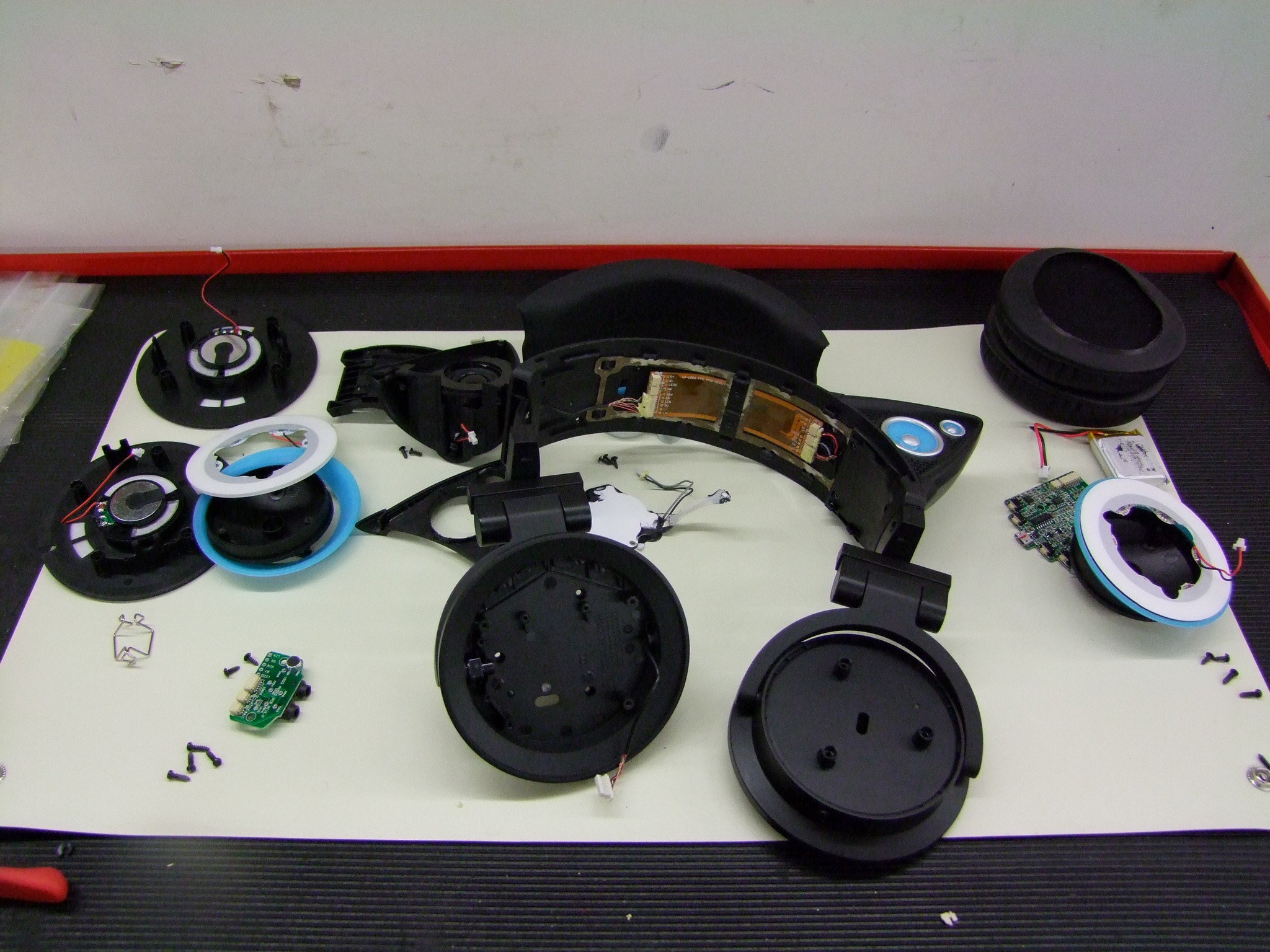
Get ready for some Beyond Unboxing, where I take these apart gratuitously in order to see what might have gone wrong with the wiring when they were dropped, and alongside, give a quick tour of consumer product design.

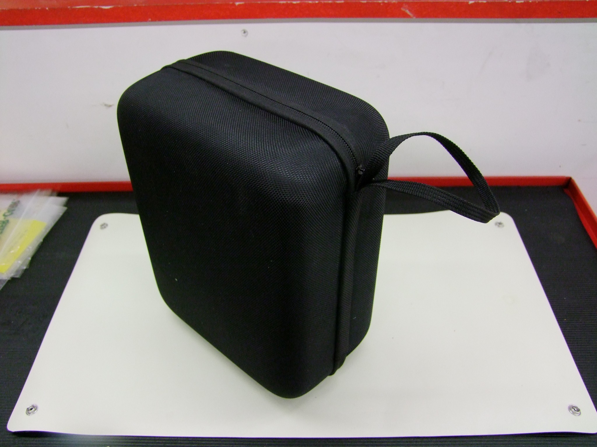
Here is the beginning of the presentation. It comes packed in a plain black, non-showy form-fitting zipper case. This is an alien concept to me, since I guess I’ve never owned “nice” headphones in my life until recently when I picked up a HyperX Cloud gaming headset secondhand, and it also had a case.

Inside the case, the headphone cable and boom mike live on the left, while an included USB micro-B cable for charging is on the right.

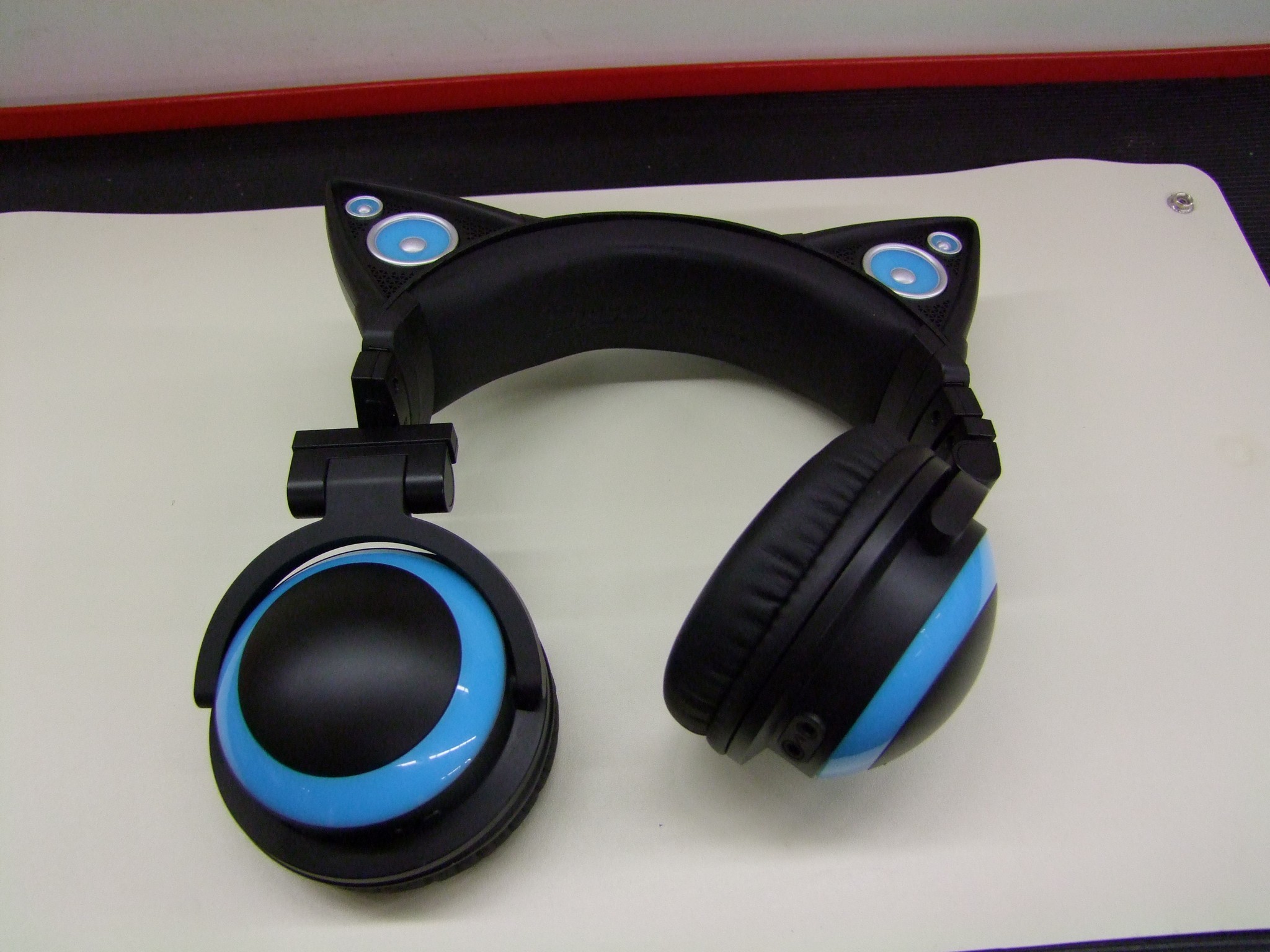
The unit by itself. Once again, I don’t claim to know anything about nice headphones. I assume they all have this many degrees of freedom!

I’m not sure if I am a fan of the sound yet. It’s quite “boomy”, reminding me of the times I tried some Beats by Dre – all bass and low end, and nothing spectacular elsewhere. I suppose it fits well with current pop and hip-hop music. Either way, it’s well known that I am a Hipster of the Nth Degree when it comes to music, so I explicitly absolve myself of any authority on this matter.

A closeup of the lighting effects. The LEDs are clearly white – just the plastic colored ring determines the color of the glow. My issue was that the right-hand side (as pictured, so “left ear) was very sporadic, like a connector was barely hanging on or something.

For those who haven’t seen these used, the headphones are passively powered via the cord like you’d expect – but the lighting and external speakers (in the ears) are battery-powered, hence it needs periodic charging.

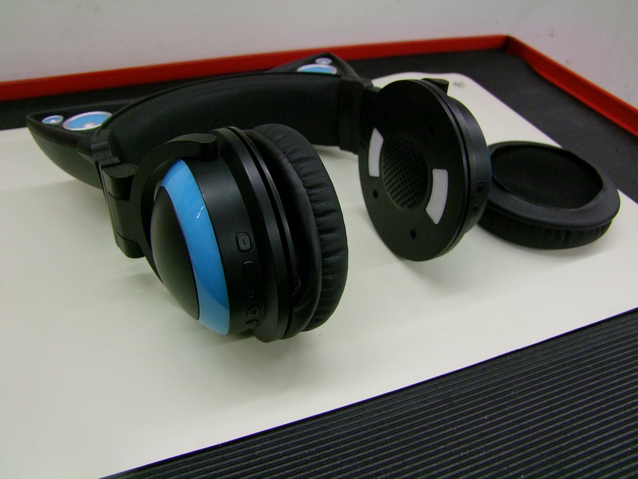
Let’s start popping stuff apart. First, the earpads can easily be slipped off (I keep wanting to call them “ear poofs”, but they have a name):

This exposes four small screws to open the housings.

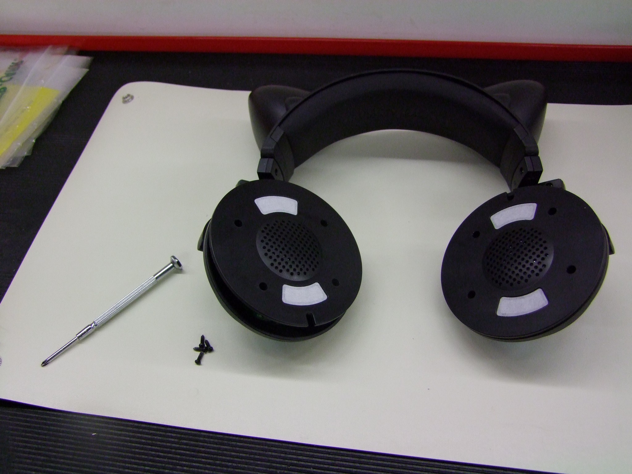
Use a small Phillips driver (I had a #1 – this seems to be correct) to open the housings.

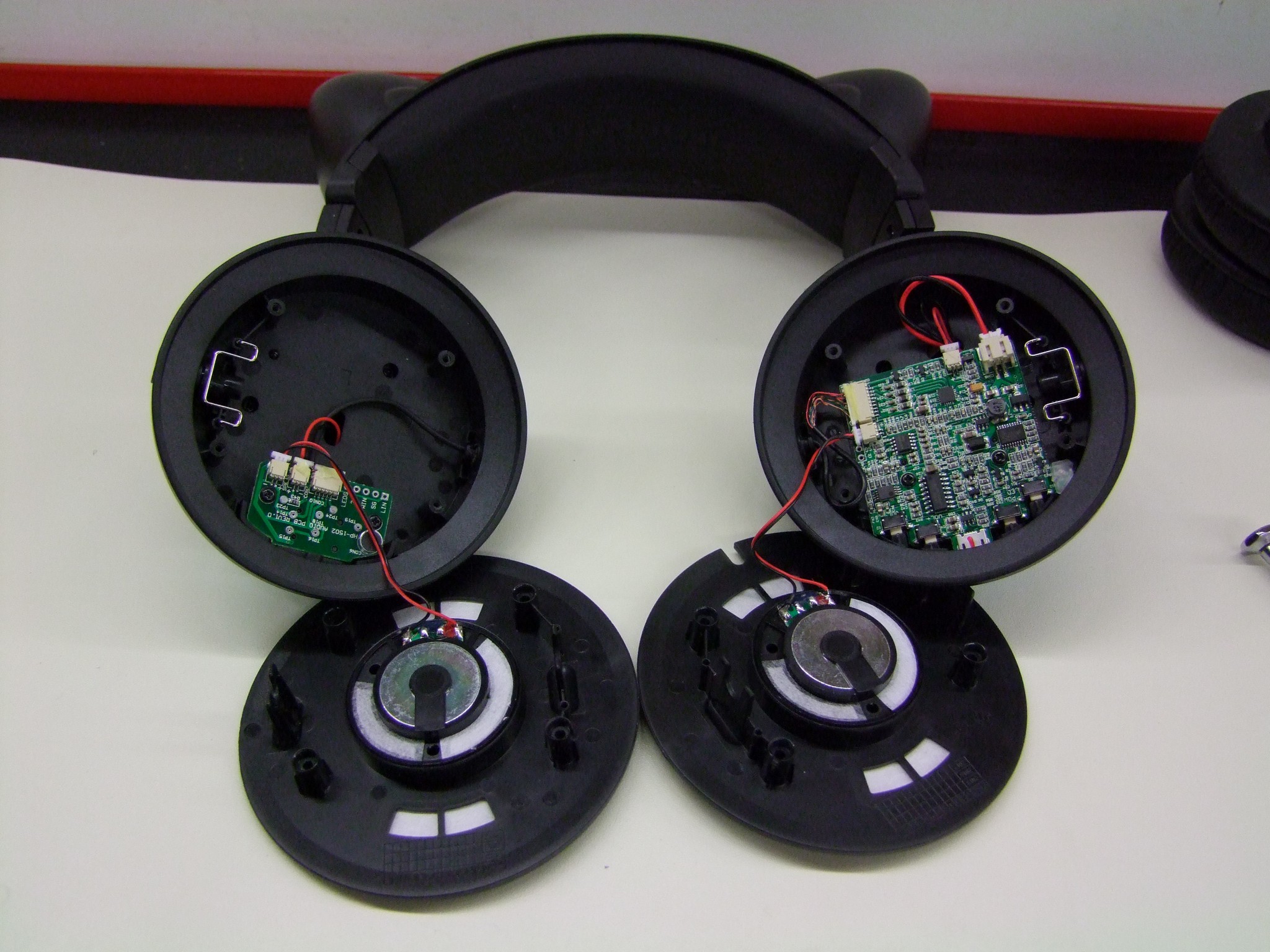
Here’s what they look like on the inside. The left side has the audio input and microphone jacks. The signals travel to the other side which contains the amplifier and power supply board.

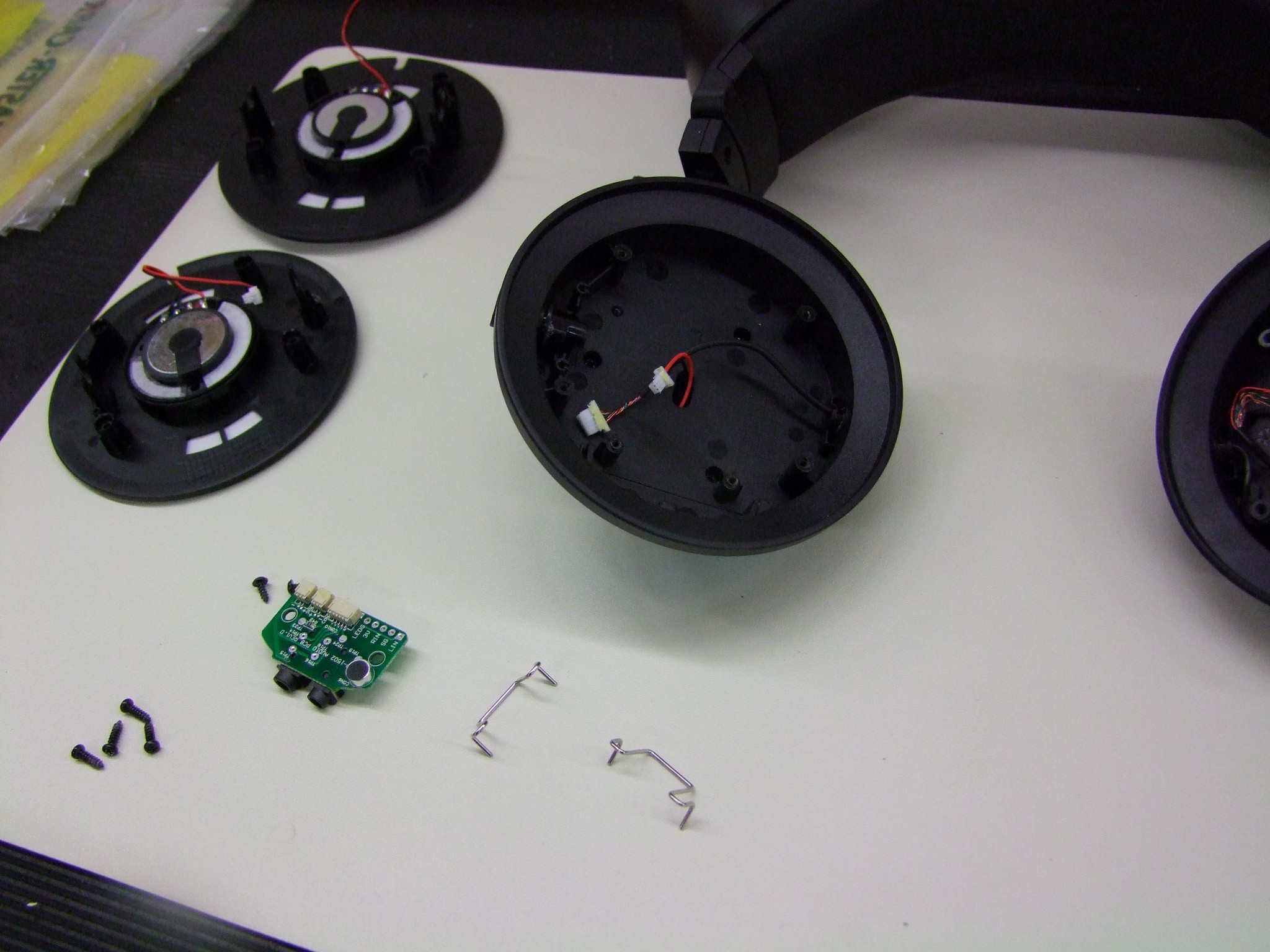
The signal input board is held in by two small screws. I also pulled out the spring clips which give the housings a bit of “detent” feel in their yokes (the forks they’re mounted to) – that’s how they stay in place if you fold them. There’s a small plastic plug that the spring clip mates with that pulls out easily. From there, the housing can be full removed…

..If you’re more careful than me. I tried to remove the housing entirely, but I misaliged the other side and broke off the other pin-like structure its mounted to. No consequence, but there will be more sloppy movement as a result. Being more careful instead of pulling harder probably could have avoided this. Alas, the difference between a hub motor and little plastic speakers.

Regardless if the housing comes off the yoke or not, the plastic accent ring and cap can be removed from the inside using four screws. Two of these are accessible only if the input board is removed.

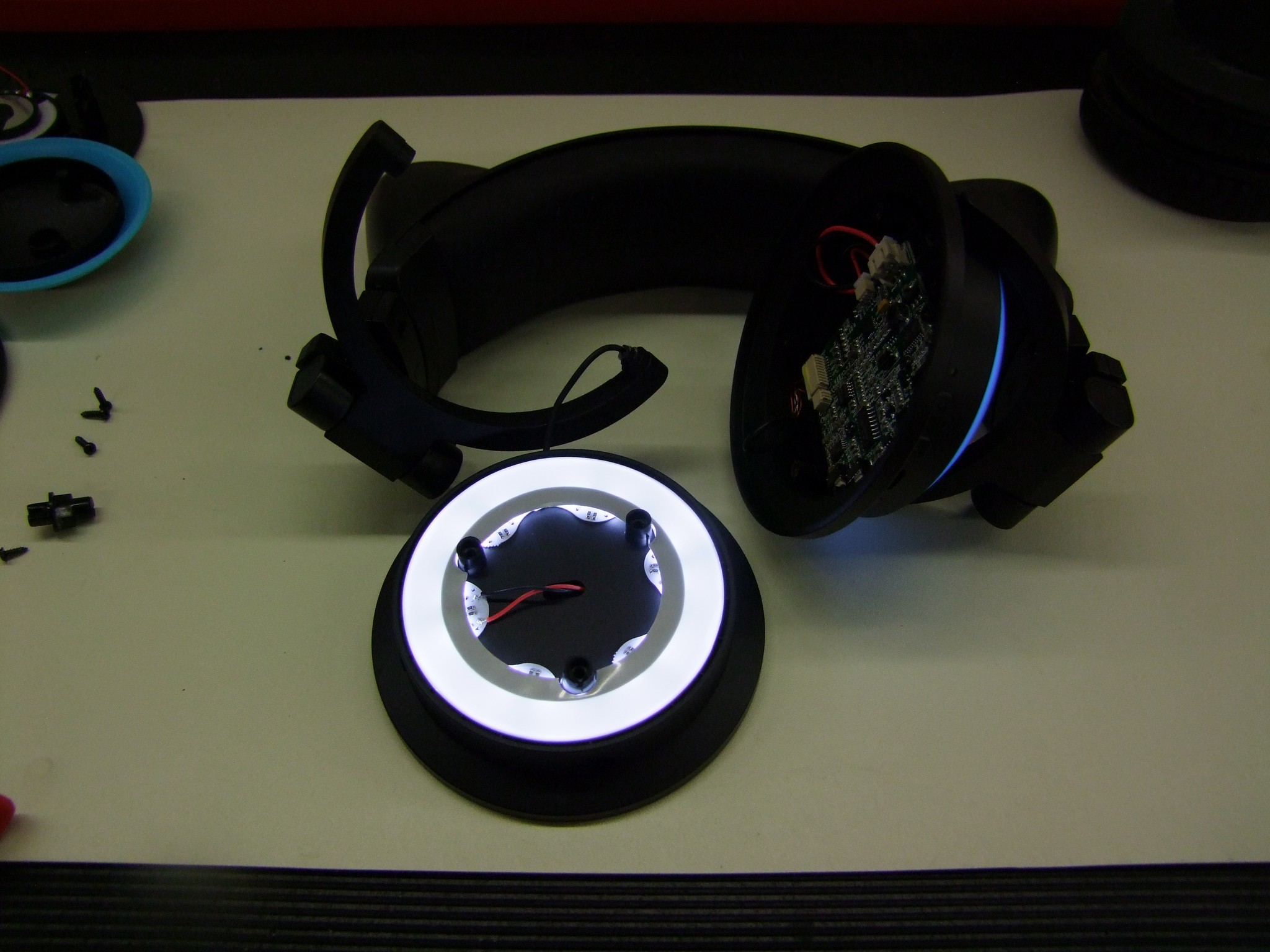
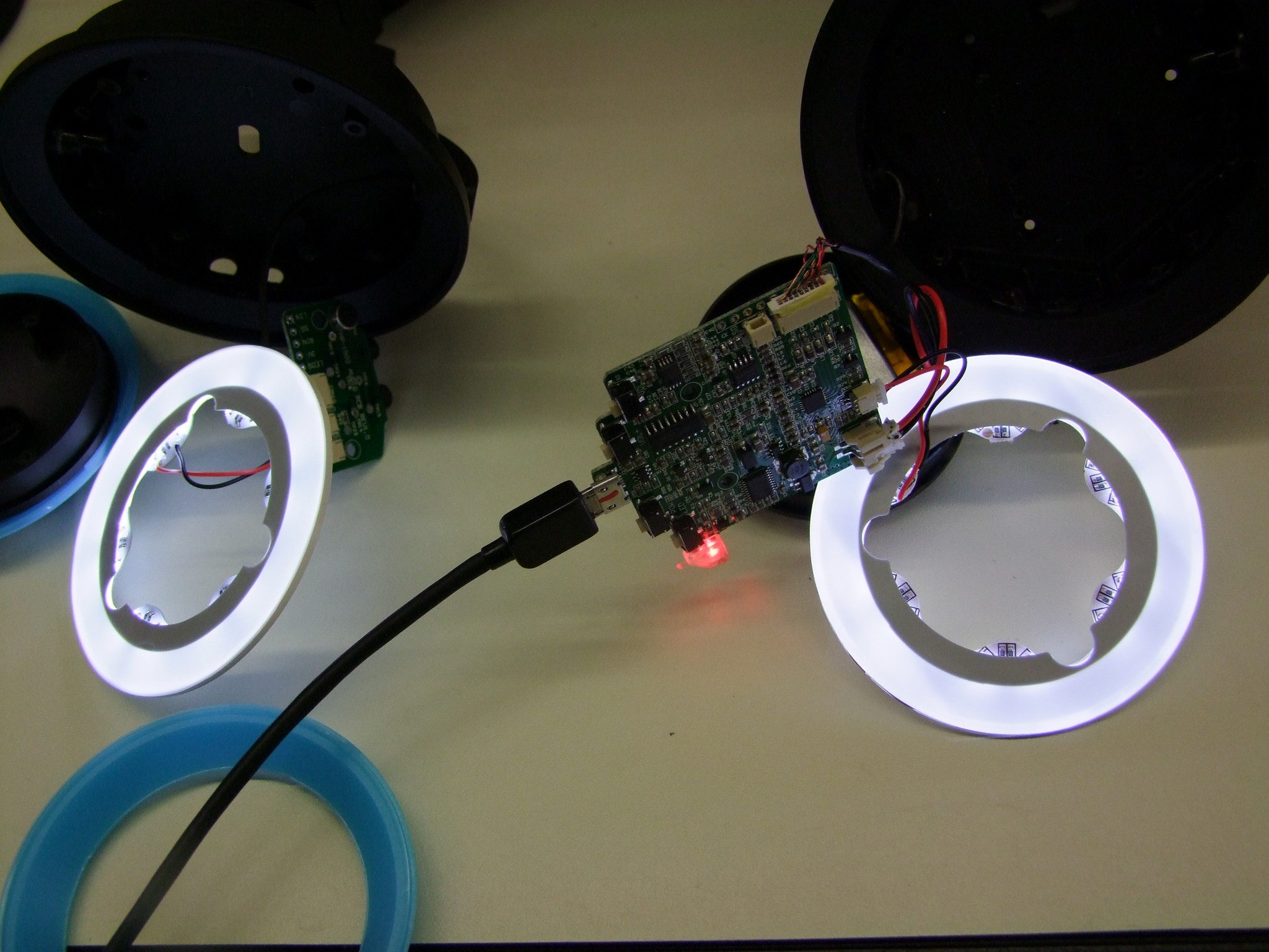
Check out the LED ring. I plugged the board back in temporarily to show the lighting effect.

The LED board is smooth white on top and made of two pieces – the printed circuit board with the LEDs is mounted to the white ring, which is a light-diffusing plastic like what would be used on a LED backlight. This softens the glow and prevents you from seeing discrete LED dots.

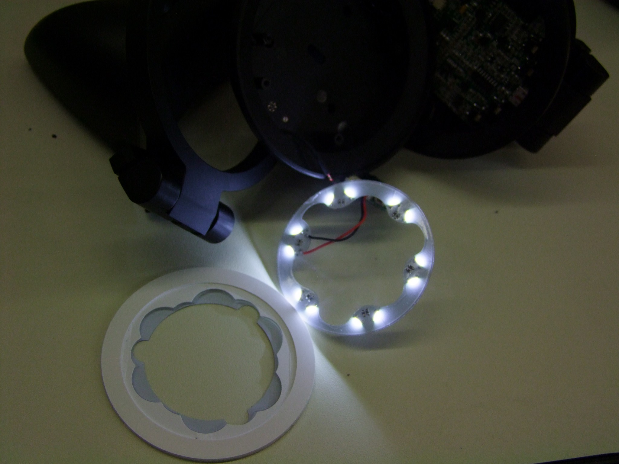
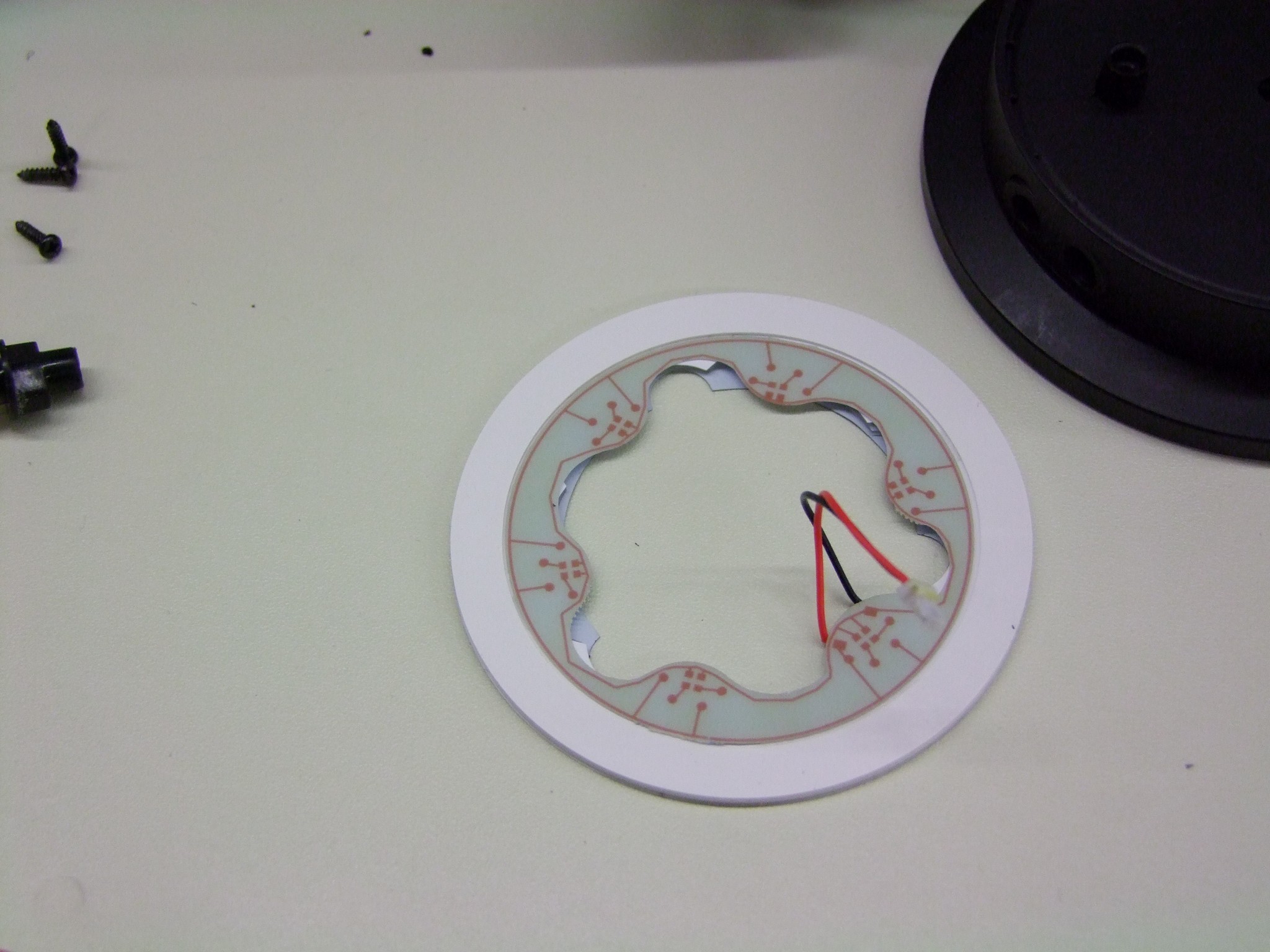
A little prying and the printed circuit board comes off. The LEDs are a unique side-emitting package instead of the far more common top-emitting type.  The LEDs fire into the internal face of the light-diffusing plastic, causing the ring to glow very evenly.

This thing has become more hardcore than I had anticipated. I was thinking that there would be an easy way to change the color of the LEDs if needed. Not so much with these – they likely chose white since it can be slightly filtered by the color of the accent ring into any of their colors. Add to that the oddball package needed and your choices are limited.

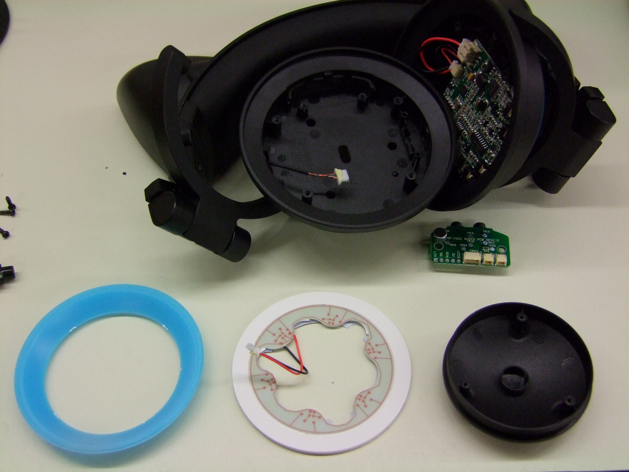
The three components of the lighting accents… or Axents, if you will.

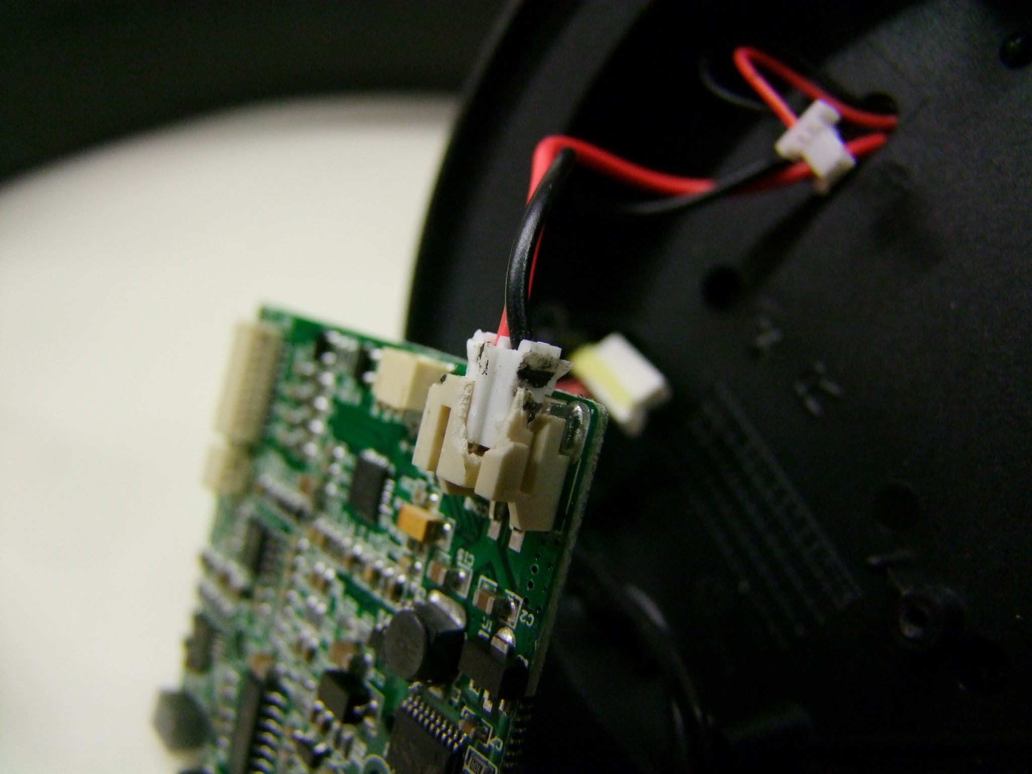
Moving to the larger board, the amplifier board – I damaged the battery connector trying to remove it. It’s held in place by a very one-way snap/detent, which I broke before getting the connector to back out. It still contacts fine however. Your experience may vary.

The other connectors are secured by a small amount of adhesive, but this comes off readily.

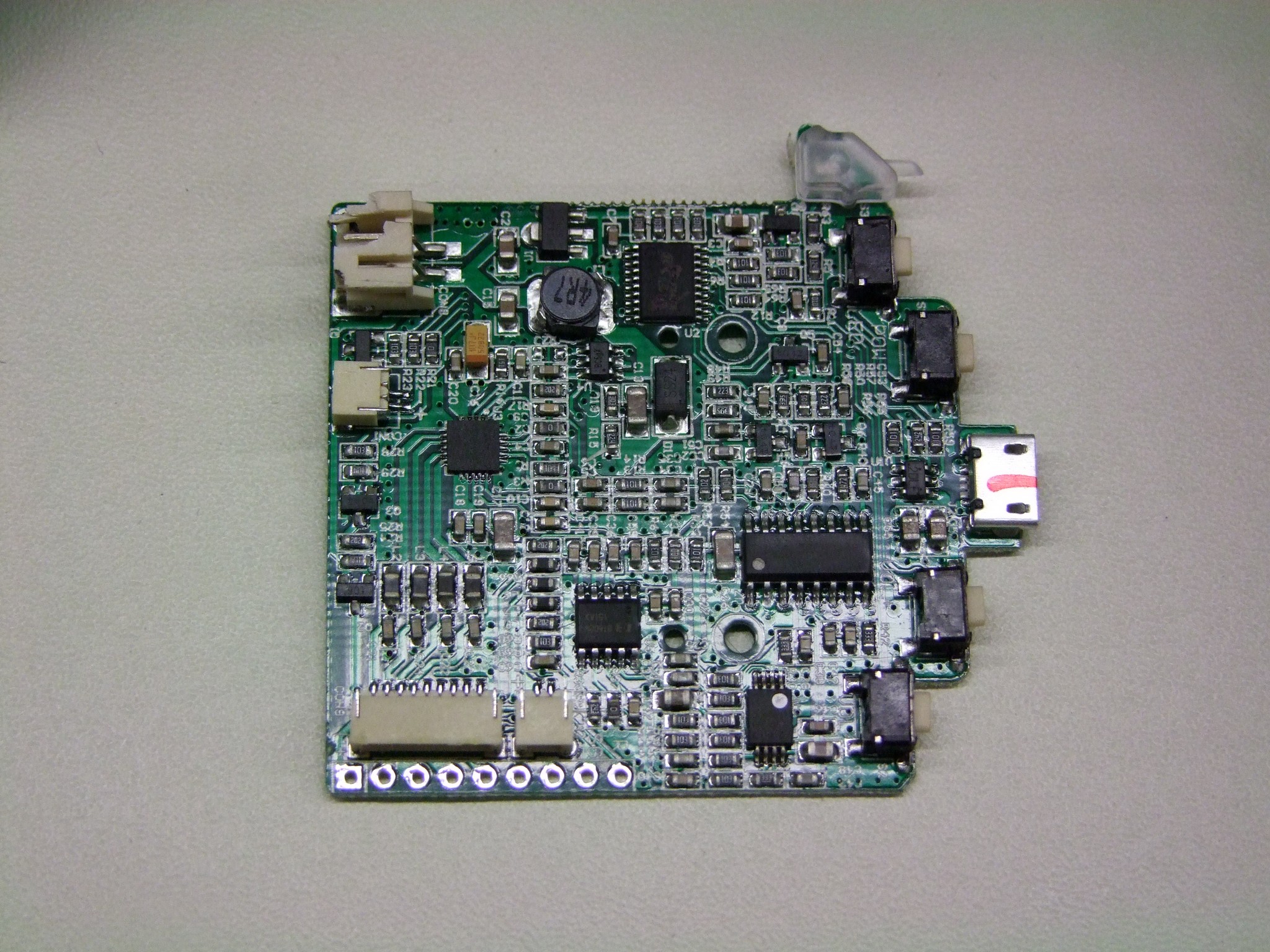
The amplifier board! I wish I could say something about its design, but it’s not a motor controller. I’ve not worked with audio ICs in the past, so unlike said motor controllers where I can tell you whether or not it’s worth using, the specific implementations of the ICs used are lost on me. All I know is it cannot flow 500 amps.

I played with searching for their datasheets, however, and in doing so I discovered that some of these are pretty damn obscure. As in, no English-language results worth following up on. I actually had better luck hopping on a Chinese search engine like Baidu. The vast majority of results regardless were trading websites, not manufacturer’s datasheets or similar, and they all claim ORIGINAL PART!!!! like it means something. It seems like a lot of these chips are genericized and made by many factories for myriad applications, so you just pick one off the cloud. The same phenomenon gave us Seg-things.

The major ICs listed, which I could track down anyway, are…

  • CSC8004 – SOIC-16 package, some kind of 2-channel amplifier. I could only find a datasheet for the 8002, but I assume the 8004 is just the 2 channel version of it.
  • TPA2017D2 – 20QFN package, a Class-D 2 channel amplifier. If I had to guess, this one drives the external ear speakers, since Class-Ds can push more power with less dissipation and the ear speakers do get quite loud.
  • SC51PS704 – an 8-bit microcontroller. Looks like one of many different 8051 clones – similar 8051 clones are used in a lot of Chinese e-bike controllers. So few pins are actually connected on it that I think it only handles button presses.
  • BT608M – this was the single hardest thing to find. There’s lots of places trying to sell it to me! When you start getting into places called “ICMiner” or “Ic-ic.com”, that’s when you part is obscure-ass. It’s also apparently a model of hospital bed, and Bluetooth-compatible speaker system. If I stopped searching early, I might have assumed it’s some kind of unimplemented Bluetooth hardware (but why even populate it then?). But I don’t think so – based on various side-channel mentions of it, such as this spammy blogpost, and this short title, I am led to believe it’s involved in the button-controlled volume for the ear speakers. If you can find this datasheet, you are better than me.
  • NJM2100 – a dual op-amp, SSOP-8 package.

Since these units are made in Taiwan and commissioned by a big company like Brookstone, I assume they have their entire network of Chinese parts traders which I realistically have no handle on at all.

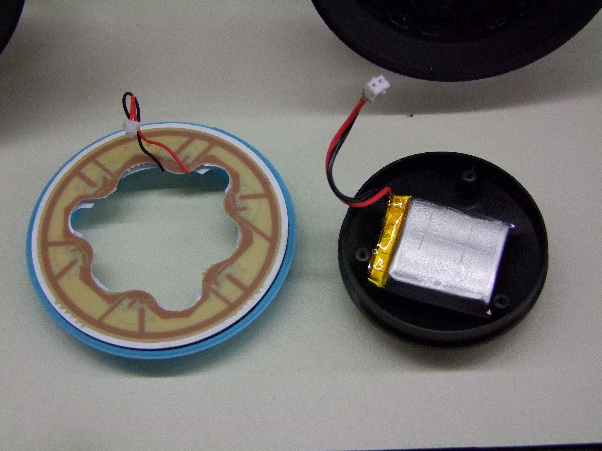
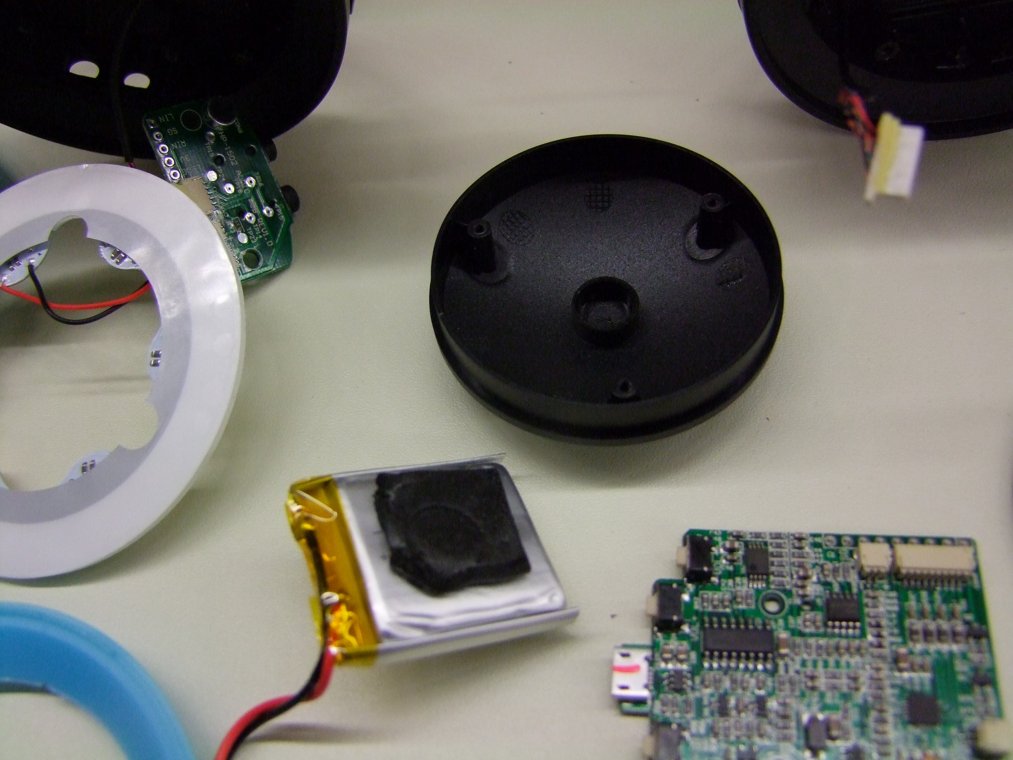
The housing on the right-hand side contains a similarly shaped though not completely identical LED board, as well as a small battery in the hollow portion of the black cap.


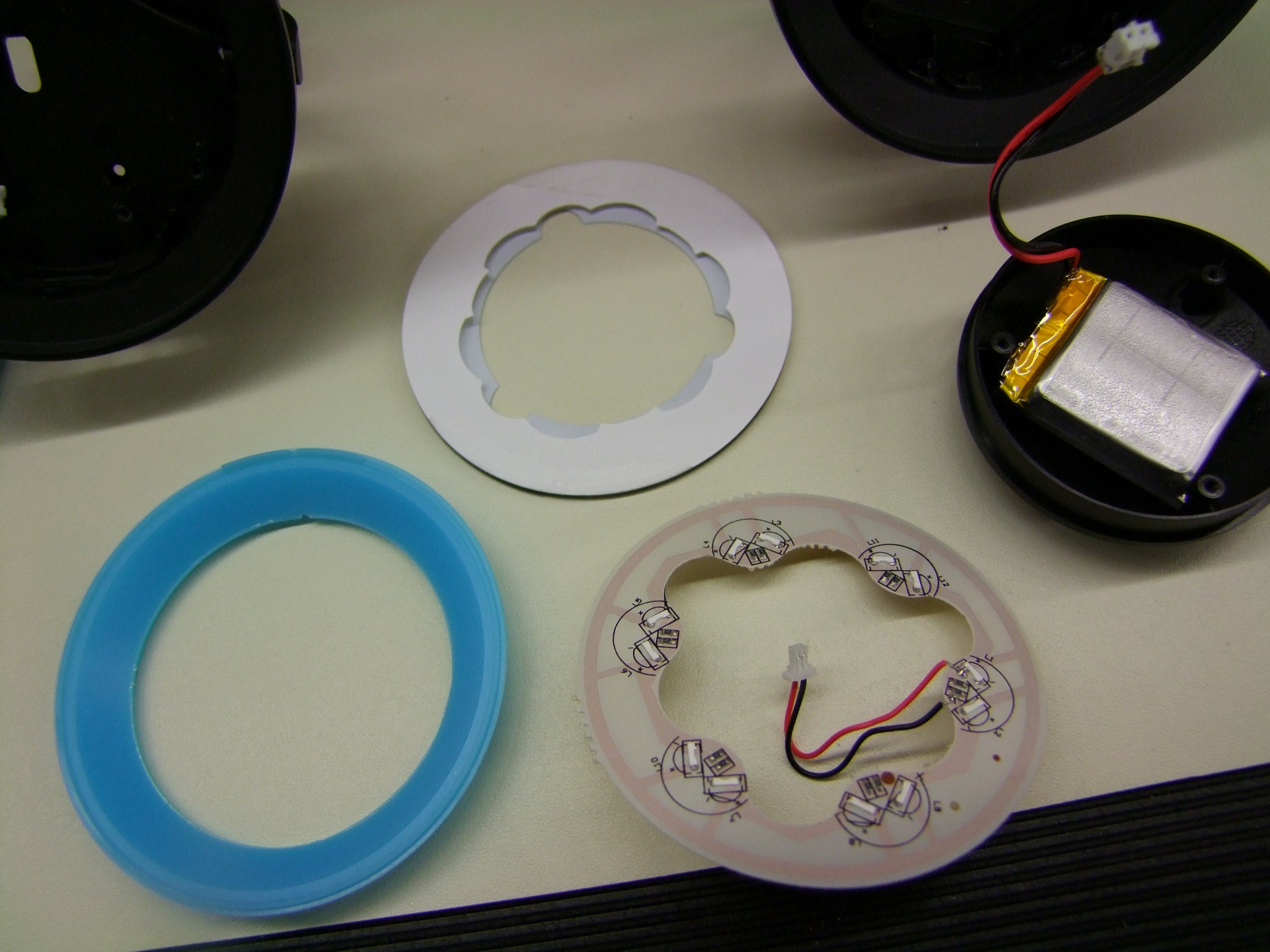
The right side LED board taken apart. This one has more markings!

I temporarily hooked both back up to check for differences in light output and the patttern, but they function pretty much identically. By the way, as soon as you disconnect the battery, the system will not arm lights or external sound until you plug it into USB power at least once.

The ratings on the battery are obscured by a bit of rubber tape.

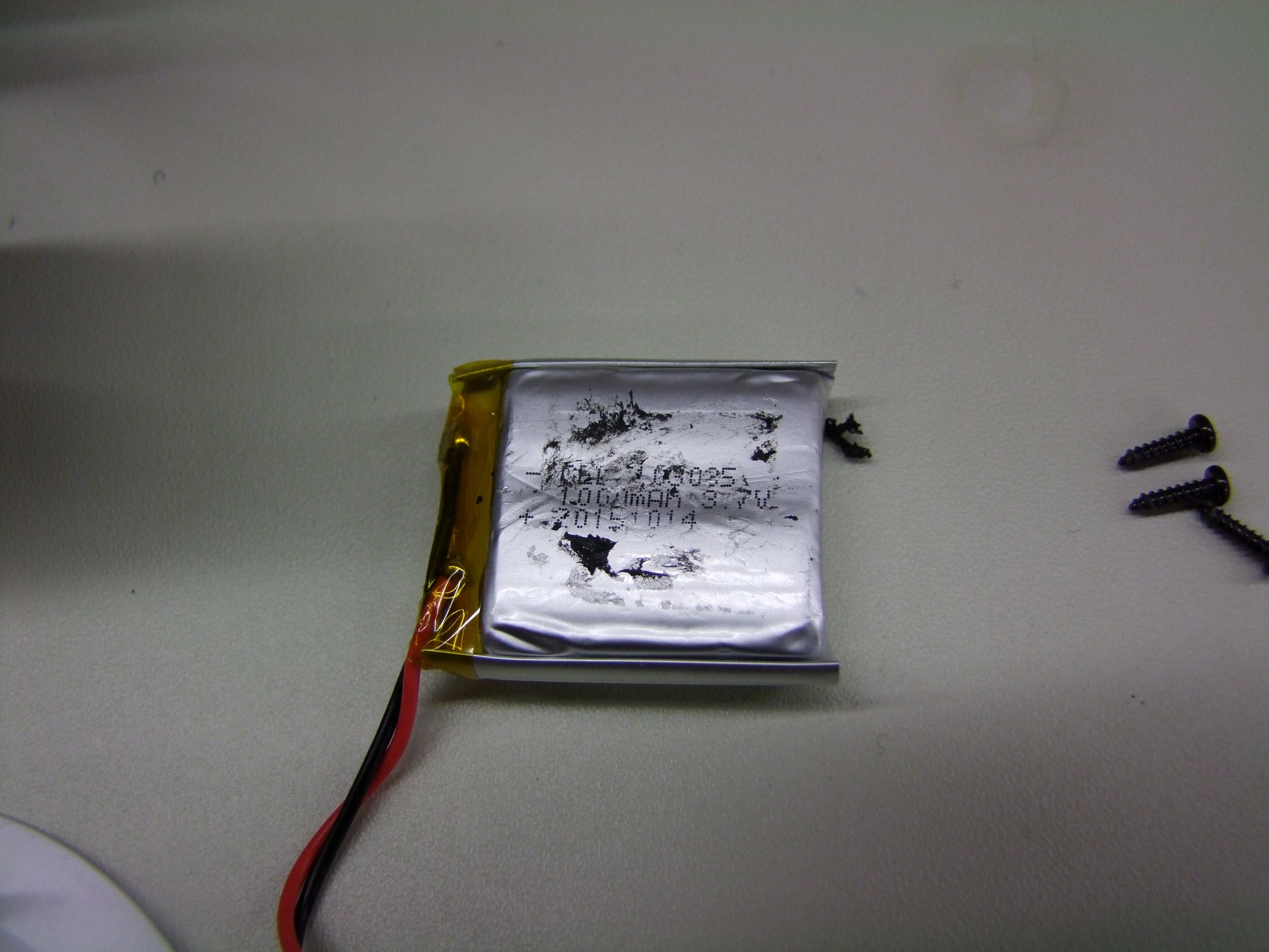
Scraping it off, you can see that the battery is 1.0Ah. Assuming you don’t crank the ear speakers at full tilt, this should last for several hours of using the lighting and ear speakers together. They claim 5 hours – I haven’t verified this yet, but some rough calculations – 3.7V * 1.0Ah is 3.7Wh nominal, of which 80% is typically available (assuming it lets you drain the battery to 20% SOC, divided by 5 hours gives an average usage of 0.6 watts. Plenty of sound for you and probably the people in your immediate vicinity.

None of this solved my lighting woes, though. The next step was to disassemble the headband to see how the signal cross from one side to another.

I’ll get this out of the way right now: I hate snap-fits. Hate everything about them, but they are the go-to these days for consumer products because of less parts cost (no hardware). But they’re generally one-way only – you try to dismantle them and they usually, you know, snap. Those that don’t just break off you can usually only get very limited assembly-disassembly cycles before they no longer hold.

That being said, the headband is held on by 18 terrifying snap-fits. Four are at the corners where the headband ends inside the little plastic bezels – pull those upwards (in the shown orientation). The headband itself has 10 snaps that pull towards the center of the loop:

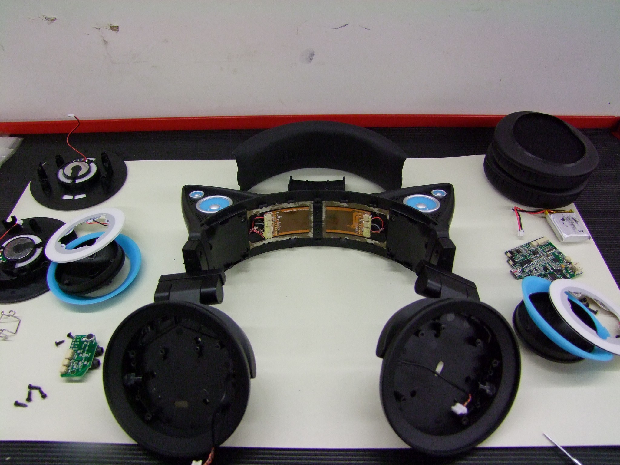
And the method of transmission is revealed. A ribbon cable! Seemingly a somewhat fragile ribbon cable. I hooked the lighting back up to see if any joints here were loose. It seems like the very act of manhandling the ribbon cable area trying to undo the snap-fits fixed whatever the issue was, because now I had both sides of lighting again.

Okay then.

From website reviews, it seems like some times there are issues with one side completely losing functionality. I suspect an issue with either this ribbon cable (I also hate ribbon cables, but just a little less) or the interconnects between it and the left- and right-housings – tiny cables made of braided Litz wire which is enamel-coated. This strikes me as being rather fragile, though most audio signal cables I have seen are made of this wire.

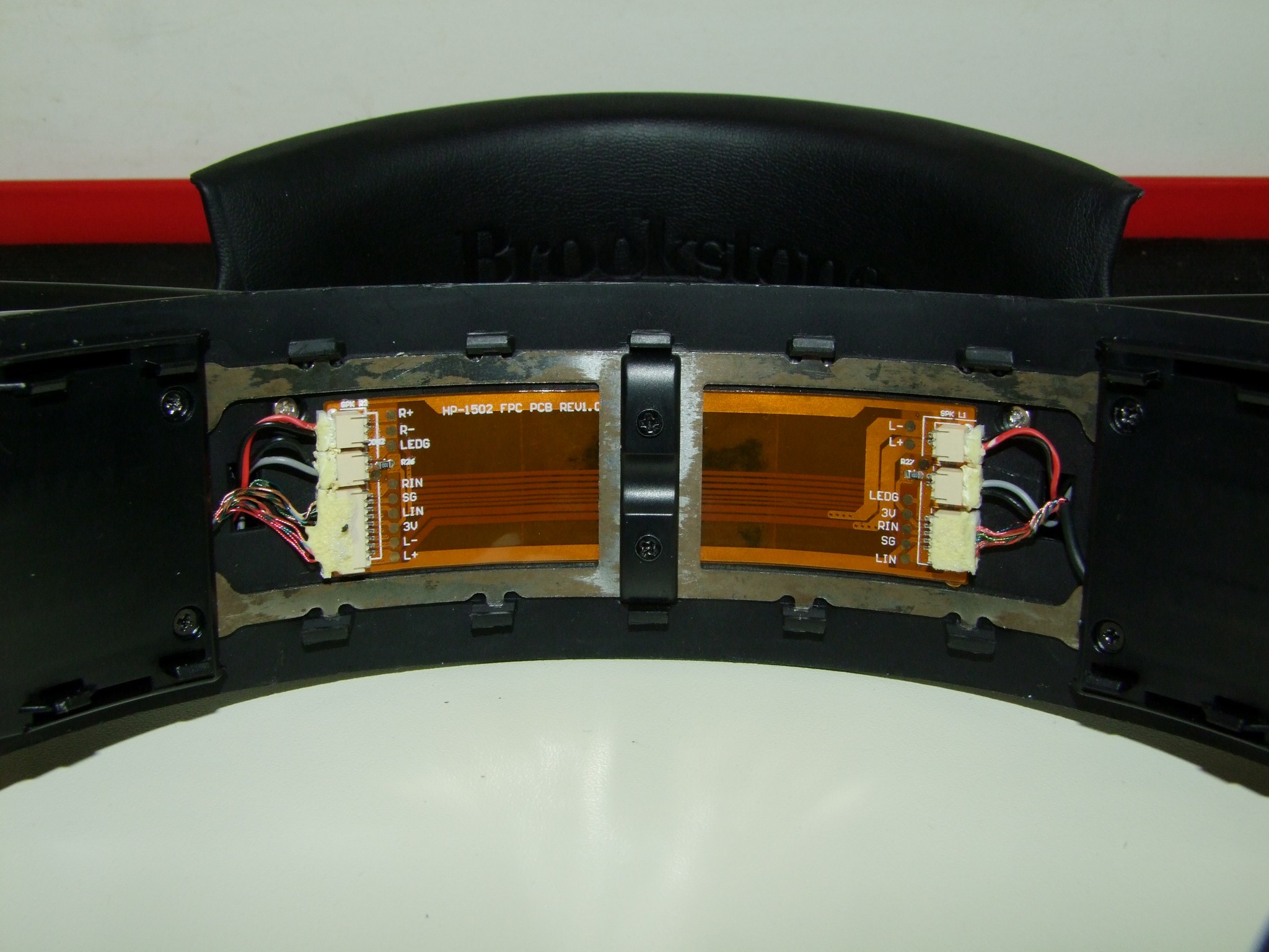
A closeup of the ribbon cable. This is oriented with the inputsside to the right.

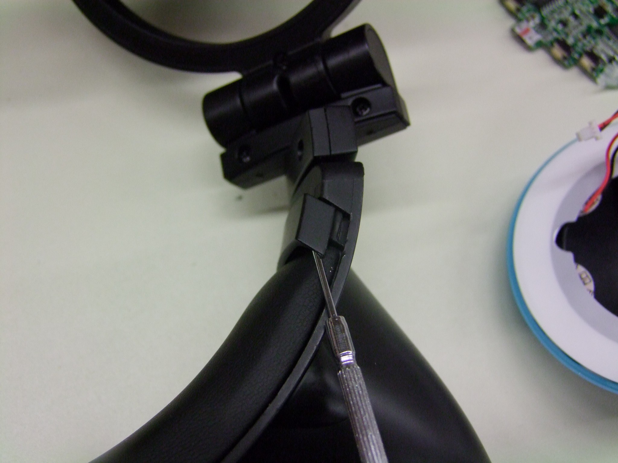
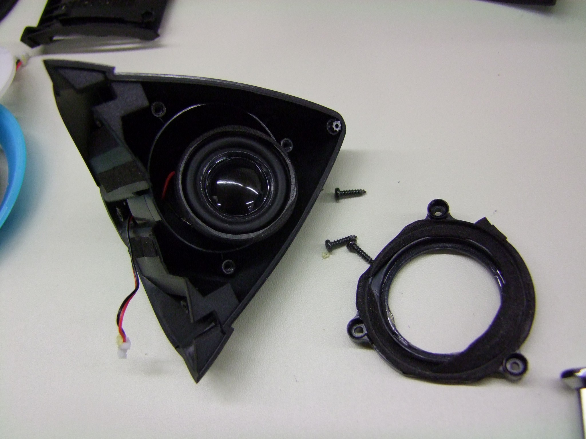
Alright, as long as I’ve gotten this far into it, let’s keep going and see what the ear speakers look like. To get to its mounting screws, there is a plastic cover which has two screws that needs to be removed. This piece is the “detent” surface for the headband adjustment, which generates the clicks you feel when you pull on it. It then slides up and away.

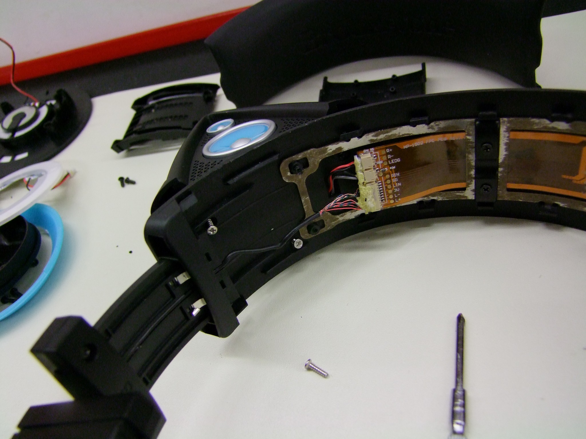
Three silver screws attach the ears. Two are directly accessible, the other one requires you to mash against the R+/R- connector pictures above a little bit.
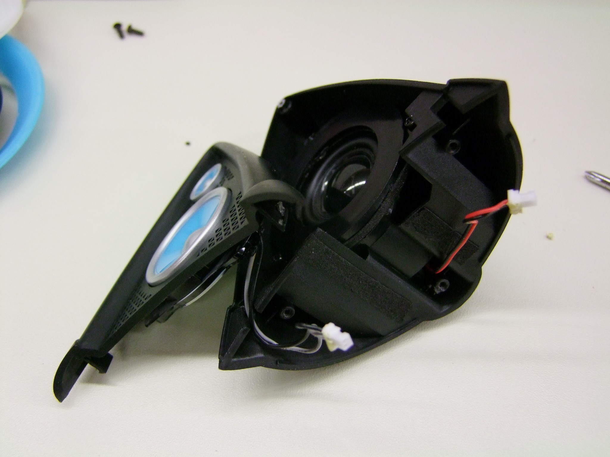
Here is an ear!

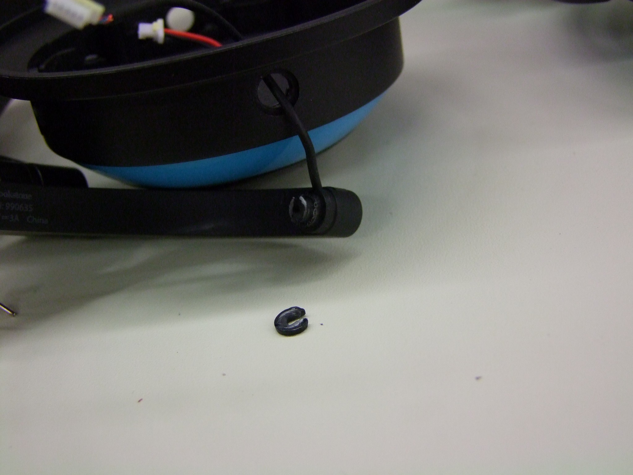
After some prodding, I found that the bottom is held in by two small snaps which are easily released, but the top appears to be a plastic snap rivet which, predictably, snapped. Its wreckage can be seen at the top of the ear.

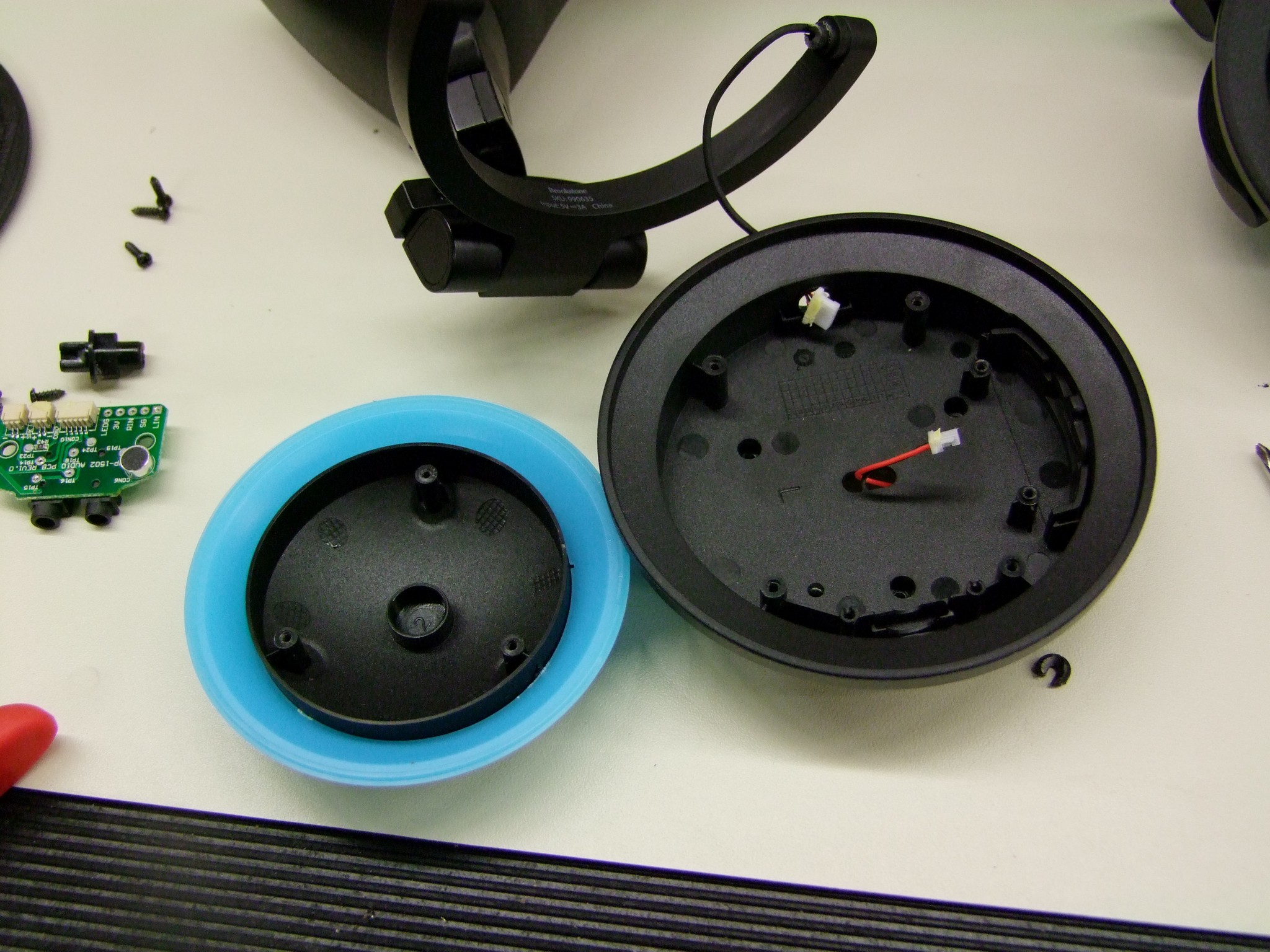
The ear speaker is a cute little 1″ driver encased a small bucket that is sealed with a ring that has some foam tape. The back of the bucket is open, but the ear is still a very small enclosure. The ear speakers sure sound like small speakers in a small plastic enclosure, like most Bluetooth speakers I’ve had the pleasure of experiencing – a ton of midrange, and not much else, muffled and tinny at the same time. An audiophile I am not.

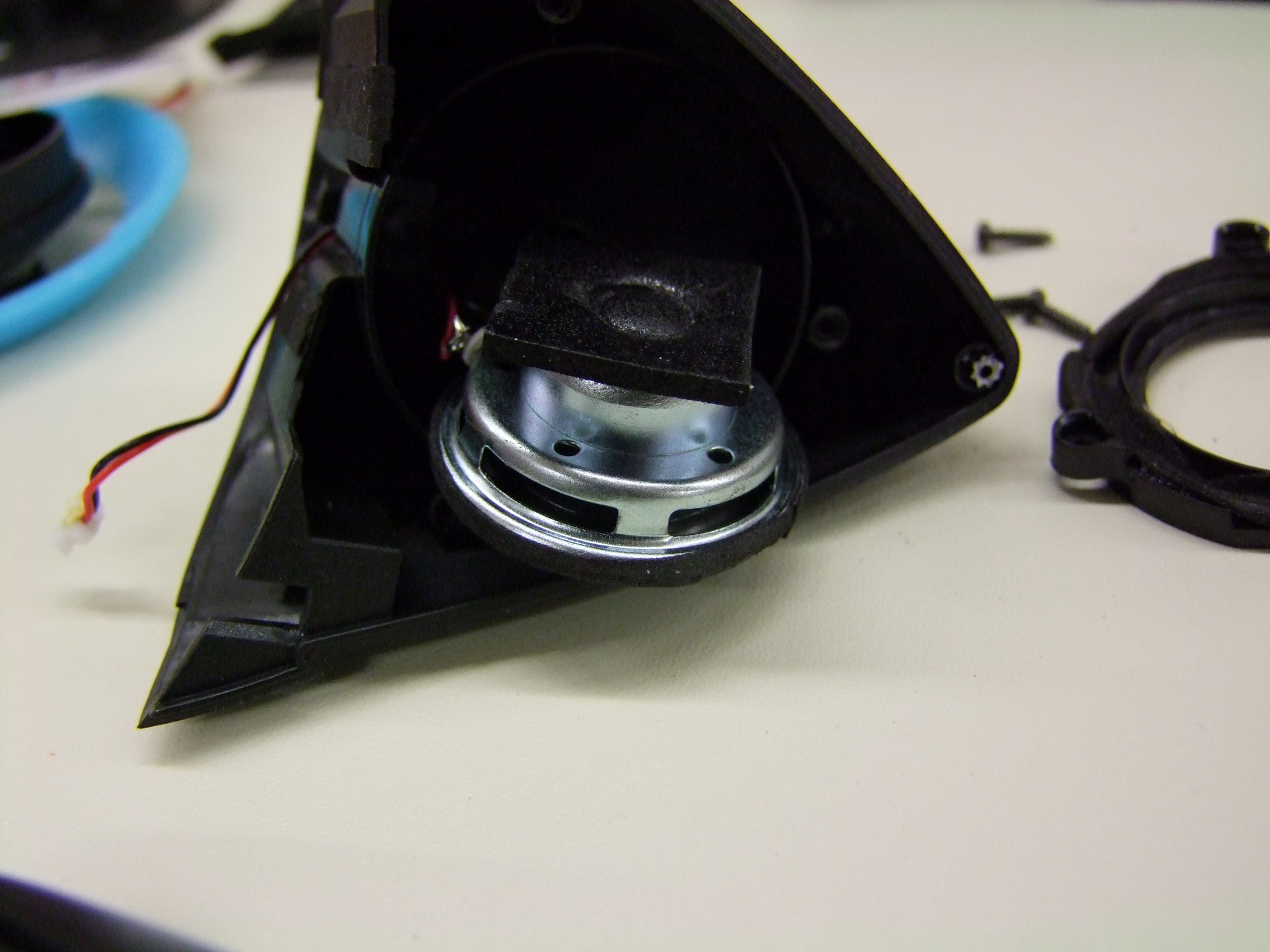
The depth of the ear speaker.

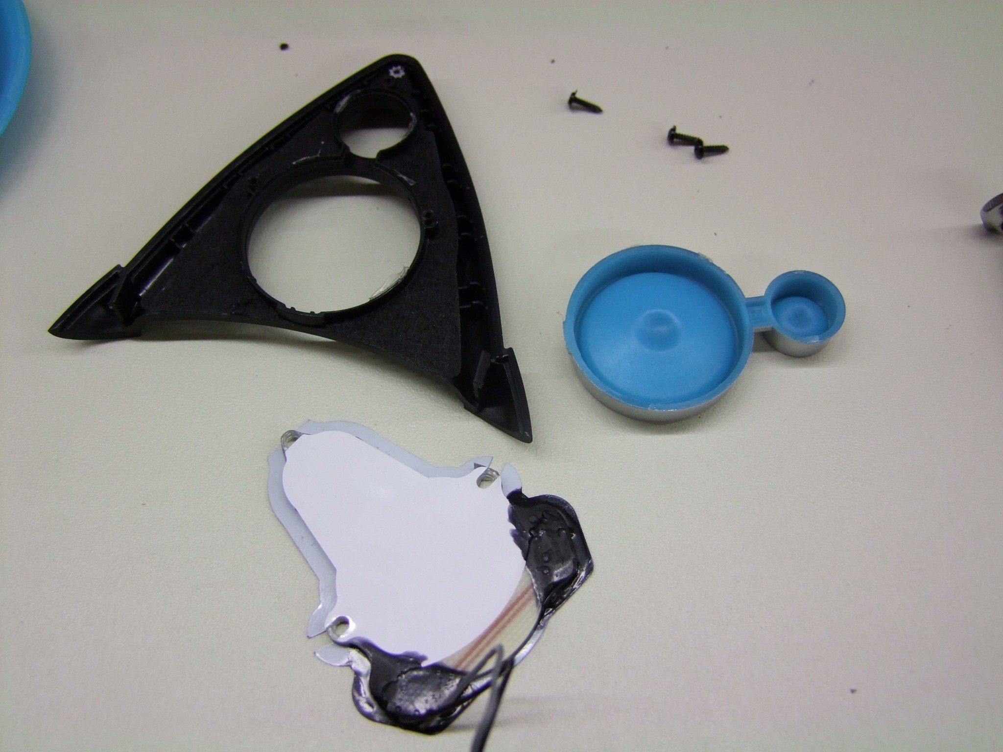
The ear accents are constructed like the ones on the headphone housing, using side-emitting LEDs pointed into light-diffusing material. The blue speaker icon is a separate piece and easily removable.

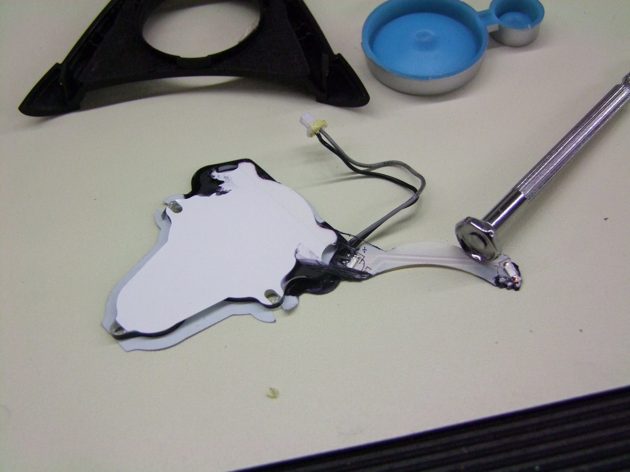
I peeled back the rubber compound holding the LEDs to the diffuser. There’s only two LEDs here.

So there you have it! Now I have no clue how to put this thing back together! Hey Brookstone…

I hope you’ve enjoyed this tour of what a modern consumer electronics product basically looks like – lots of molded plastic, snap fits, and housing little printed circuit boards. I feel like they still have a few little quality issues to overcome, but in general the amount of effort that was put into these was beyond what I expected.

That same level of effort also makes these things much harder to modify, as I had said at the beginning. Why would I be thinking of modifying them though!? That’s because of….

#Season2, Or: BattleBots, the Anime?!

I’ve been throwing around this false hashtag #weeabot on purpose for a little while now (false meaning I don’t ACTUALLY have a Twitter or Instagram or Tumblr account where tags actually, you know, matter – I consider Facenet hashtags to be kind of vestigial) on places like r/battlebots or the BB official pages. Anyways, what it embodies is my continued unstated, half-assed life goal to increase the intersection between engineering and anime. Put simply, there’s just not enough of it – at least in meaningful ways. Just like I like my science fiction rather high up on the hardness scale, I like my engineering depictions somewhat plausible. This in general never happens.

I also have a desire to offer counterpoint to the likes of Kantai Collection, which has (in my opinion) completely ruined the mecha musume genre. I like girls and machinery, and consequently girls with machinery, but Kancolle’s character designs essentially have nothing to do with the machinery. You don’t just weld battleship parts to a schoolgirl archetype and try to sell it to me. And the worst part is, it’s spawned endless look-alikes which have the same problem. It’s gotten so bad that even Toyota has started doing it. That’s truly when your genre jumps the shark*.

I can’t not say IMPOSSIBRU, sorry.

To matter the reason, if I don’t like anything on the market, I tend to make my own. RageBridge (and RageBridge 2) was a direct response to how much other motor controllers in the market segment sucked (AND STILL SUCK).

Now, an artist I am not, but luckily I have the help of the magical and talented Cynthia, who also brought you Arduino-chan as seen here last year. Besides returning again to help with the fabrication and electrical work for next generation Overhaul, she will also be creating team cosplays uniforms designs, as well as an “Overhaul character” in the vein of the mecha musume series and the, umm, Priusettes, which you loving and adoring fans may cosplay as in the live audience! One that doesn’t suck.

Here is a preview of things to come…

So there you have it. While I’ll be cranking on making OH2 hypothetically easier to service, faster, and more reliable (read: less fail), she will be making the brand. A robot TV show is about more than just the robots, after all. And especially in this day and age, you won’t really know what becomes popular due to the Internet Hype Machine ahead of time, so perhaps this is an exciting new direction. Hell, if all goes well, we’ll have a character for EVERY  #SEASNON2 entry – there will be surely something for everybody.

And lastly – so why did I feel the need to “mod” the Axent Wear? Because the shade of blue doesn’t match the new “team color” (and robot thematic color) for OH2, digital goddess and “That girl Charles has a sticker of on everything he owns” Hatsune Miku:

Of course it’s a Miku-van

It’s more of an aqua/cyan color, which involves a wavelength of LED that is not common at all, much less in sideshooter package. What I’ll probably just do is 3D print translucent-white accent rings (the currently blue parts) and coat them with something that is more aqua. (To my knowledge, nobody makes an already-translucent aqua/cyan 3D print filament).

Oh yeah, definitely expect the whole bot – however it ends up looking – to be plastered in character stickers and corresponding thematic paintwork. Since Miku is a copyrighted character, it will probably be whatever the OH2 character ends up as. I have a few places that can provide the necessary vinyl graphics.

And finally, for something vaguely robot related…

Those are rubber bumpies, similar to the ones used on OH1 but smaller and more numerous. Yum, bumpies. All shall be explained soon – I have over sixty design screenshots of OH2 to write up as soon as I’m more than 90% sure I won’t get kickb&4lyf for doing so.

#season2 #weeabot

*Not to shit on Toyota too hard for this campaign, since they did hire many different amateur artists to make the individual designs. It’s made the Prius about 2% less horrifying in my mind.

A New Beginning, the Second Story; RageBridge 2 FINALLY Going to Manufacturing; Season 2 and #SADBOT2016

It’s official – after December 31st of this year, my contract with MIT as the MIT-SUTD Collaboration‘s International Design Center shopmaster will end, and will not be renewed. As of then, I will no longer have official ties to MIT. Hard to believe, eh?!

There’s no better timing for this, too, as #season2 is on the horizon early next year. My goal is to use this same epochal shock to usher Equals Zero Designs into prime-time, with the release of RageBridge 2 and a host of other stuff I’ve been working on this fall semester – stay tuned for that.

Ultimately, it was a combination of the fear of complacency as well as organizational changes that is pushing me to move on. First, because I have commitment issues and can see myself being a shop instructor & design class instructor for the next q years, which frankly scares the shit out of me. Sorry, ladies. Second, the IDC has moved on from its more “Wild West” days of supporting any which project, towards a more professional research-centered model with strong ties to industry. This is without a doubt better for the Center and will make it sustainable past its years with the MIT-SUTD collaboration alone, but I just didn’t see myself contributing to it any longer. I’m one of the last of the “original generation” of IDC inhabitants, and that presence has made itself painfully obvious in the preceding few months.

The thing I’ll miss the most is not anything to do with the Center, or even “my own” shop, but my interactions with the student maker community and being the go-to guy for late-night uncommon parts and advice, because yeah, of course I have one and of course I’m upstairs right now. That, and not being able to continue the great experiment that is 2.00gokart, but perhaps this will be remedied in due time.

In the coming weeks, I’ll be winding down my operations at MIT and shifting most of it over…

…to my little corner at the Art is a NSA sylum. What I might lose in the coziness of “my shop” I gain in a real, dedicated space for shenanigans and a much wider array of on-site resources and a massive community of deranged makey-types. Thus begins the story of Big Chuck’s Robot Warehouse & Auto Body Center. What, you thought I was kidding?

The downside? I have so much shit to move.

So many more people making and building things at MIT is a mixed blessing: nowadays nobody can get their own little private corner for too long. I’m currently trying to knock down my stuff load, which dates back to mid-2007, across 3 or 4 different sorting systems (at least 1 of which is just “NONE”), and several midden-esque locations. So, perhaps watch out on the For Sale page soon

ragebridge2

Oh dear, I’ve officially become one of those delayed crowdfunding product people in addition to being just a crowdfunding product person.

Ragebridge2 got basically pushed back a month to resolve one of the biggest issues plaguing it from the start: the one channel “giga-mode” where the two sides are tied together so Rage becomes a single channel twice-as-awesome controller. A lot of prospective users were asking for this so Rage could conceivably be used in a heavier robot design. For example, the two sides put together at 150 amps limited would be plenty of current for, say, an Ampflow A28-150 motor.

Now, how hard could this one-channel thing possibly be? Isn’t it just copying and pasting the output of one control loop cycle to the other?!

Well, basically. But first, there were secondary issues that had to be resolved.


One thing that eternally plagues power conversion and motor control designers is noise. Switching tens or hundreds of amps thousands of times a second is not easy on sensitive logic. The bigger the parts get and the higher the amps go, the more likely you’ll start seeing things like optical isolation and fully isolated independent gate drive supplies, and the like. I think Rage is on the big end of what is basically “non-isolated” designs, where power and logic ground eventually meet on the same board. When they do, layouts and trace routing become as critical (if not MORE critical) than exactly what FETs you use…. I could have the most hardcore power devices in the world, and my board would just reset over and over if the current draw went over 5 amps or something if I dropped a haphazard or autorouted (shudder) layout.

Now, fortunately, for Rage, the critical current wasn’t 5 amps, but more like about 130-150 amps. On very hard reversing with the current limits near the top, the board would still trip up. However, it was no longer the microcontroller resetting, but the Allegro A3941 chips themselves that were having issues.  In fact, one side (channel 1) would preferentially shut down.

In fact, here’s a scope trace between low-side return (LSS) of the gate drive chip and my logic supply ground measured at the logic bus capacitor, on a 100%-to-0% step where I just kind of let go of the transmitter stick, with the current limiter set to maximum (75A) per channel. That’s a nearly 6 volt peak to peak smash, especially with a strong negative component. And this was at PWM frequency – happening 15,000 times a second.

If Rage were in dual-channel mode, this resulted in that side simply no longer responding, needing a reset to clear. If it were in single-channel mode, well… stuff generally blew up.

There wasn’t much more trace and component placement optimization I could make, however. I repositioned several of the gate drive traces, and more importantly, moved where the gate drive chips got access to VDD (system voltage) and VSS (system ground), specifically moving them away from “right under the drain tab”. I’m not sure why I even did that, but…

One last thing I decided to finally do was to airgap the whole logic ground plane.

Before, the plane filled the whole area that is now black in the center. This placed it right next to the high-power planes and the switching output of the motor, not to mention the high dV/dt gate drive traces. This is no longer the case.

All of these changes called for a new board revision, number 6. I decided to try a new-to-me vendor that I’d been clued into, 3pcb.com, not to be confused with 4pcb.com. I see what you did there.

They have the quickest turnaround of any place I’ve used so far that doesn’t cost four-figures. I’ve actually since used PCBWay for a few more sensor boards and consistently get orders in on Wednesday afternoon, and receive them the following Monday, including shipping time with an air express service and which doesn’t even cost that much. The “downside” is no “fancy stuff” like 4 layers, microvias, plated holes and edges, etc… on your boards or it takes as long as it normally does.

So WHAT’S IN THE BOX?

It, uhh… Oops.

I’m pretty sure I clicked on the wrong choices for LPI (solder mask) color and silkscreen (text) color. The buttons are actually next to each other, okay?

Just in time for the cold season, the wild RageBridge gains a brilliant white winter coat to better camouflage itself against low-inductance motors and people who don’t know how to solder.

To be fair, this doesn’t look bad. However, the white board is easily stained by flux, and after reflow-soldering the FETs and gate driver ICs, there’s obvious yellowing of the board to a more ‘off white’ or ‘soft white’ kind of color. I think this is partly the flux, and partly because I cooked it too long. My process is not nearly as controlled as a production reflow line, so it’s not an entirely correct criticism. For production, I’m going to stick with black.

But did this revision solve anything? Quantitatively, I haven’t recharacterized the noise, but qualitatively, I haven’t gotten the board to reset or shut down in any way once. It will now happily grenade the power traces on a cross-side short, and continue working once I bridge the gap. This is all while driving a motor like 10 times larger than what it should be driving.

Well, that means it’s still blowing up in single-channel mode. It turns out there were quite a few structural problems with the firmware that allowed the input-taking loop to ‘override’ the current control loop. As the fastest loop in the code, the CC loop is what should be controlling the outputs at all times. The issue centered around passing variable values back and forth between the two loops. This itself was not causing the board to explode, per se. It needed an accomplice on the hardware side.

The other issue was that my deadtime between high- and low-side FETs being turned on was too small for the switching time.

The red trace is the gate of the high side FET discharging, turning the FET off, and the yellow trace is the corresponding low-side turning on. There’s very little error room here. It seems like the high side barely makes it off before the low side turns on.

Again, not very bad if the two sides were separate, but if they were switch together, all of the components better match perfectly. A few extra dozen nanoseconds here and there in delay and switching time differences would cause one side to be momentarily on while the other is off, or vice versa.  When this happened, there was an audible click from the capacitors as the cross-conducting FETs swished what must be peaks of hundreds of amps out of them and in a loop around the board. That was my sign to, umm, power everything off right now.

Prior to this, the board only exploded made terrifying sounds at very high throttle percentages (e.g. above 95%). I found out that the “output overriding” issues in the firmware were permitting very high PWM duty cycles, since the input-taking loop does not constrain its outputs to include deadbands on the low end (0-5%) and high end (95-100%). When this happens, it means the low side FETs occasionally turn half-assedly on and off due to the rapid on-and-off cycle.

I increased the deadtime to a safer margin to test again. The combination of correcting my variable-passing and adding more deadtime made for perfection! I just had to make sure that the outputs never went above about 95% – from there, it jumps to 100% – to avoid the possibility of one-side off (no FETs on) and one-side on, which is a slightly less bad case of one-side-high, one-side-low.

This jump is handled by a conditional in the fast (current limiting) loop. In practical use, this is almost unnoticeable (and is also used in RageBridge 1 and basically all other motor controllers, to avoid the things I explained previously)

With these issues resolved, Rage is now incredibly close to production. I’ve put in for the assembly quote and have already amassed the Bill of Materials. Associated tasks include getting quotes for heat sink manufacturing, and of course, in due time, readying the website and producing documentation. I hope to have everything out the door by mid-week, so Indiegooglers stay tuned for a huge update!

sadbot2016

Way back during the middle of #season1, when we thought building a 250lb robot in roughly 5-6 weeks was going to be a breeze, I came up with the idea of a “practice assbot” for the 4 newer team members to construct so we can practice driving Overhaul v1 against it. Because, y’know, we were totally going to finish a week ahead of time and have time for everyone to take a turn at it and decide the chief driver on who’s the most skilled and… okay, that kind of died a little bit as we were welding the last bits of the new lifter assembly together on Tuesday night of production week.

But we were left with this tool, which just had to be used on something. The original plan was to put some wheelchair motors and tires on a square tube frame (leftovers from constructiong the OH1 frame) and throw this on a third of said motor. It would just be an irritating practice opponent.

During the brief interlude before #season2 work took off in earnest, I decided to take this project to fruition and adopt it, much like I am adopting the name and concept of Overhaul itself – more on this in detail soon, is my hope. I wanted first and foremost to have a 250lb-class driving practice machine. The difference between driving a 30lber and Overhaul was much like a small sports coupe and an overladen Chinatown bus. The second goal would be to test stupid experiments for Overhaul V2 (….more details on this soon, again, as I hope!) and basically make a “prototype” to make sure that certain bad ideas work, or are ruled out, before the proper build.

So I extracted OH1’s wheelpods from the apartment  and proceeded to think of the simplest, most durable frame I could build around it. Each wheelpod had four mounting points which were rubber shock isolators, so I just needed something to bind it together. A simple tube frame would have sufficed, but it was actually not heavy enough. To really get in the weight range I needed, there had to be much more steel.

My salvation came in the form of giant C-channel, specifically the “6 inch x 10.5lb per foot” type. That’s how it’s sold, pounds of STEEL per foot. In all, the thing above contains about 140lb of steel alone. Add in two roughly 25lb wheelpods and  batteries and it should be right up against ~220lb, so I could run this in other 220lb Heavy events if I really felt like it. The wall thickness is around 1/2″. It’s just a blob of steel.

But what it really needed was the Stick of Poking. For that, I conjured up a quick structure to contain a modified, chopped-down version of it.

The gear ratio may or may not be similar to one I intend to use in OH2’s main lifter, with the tip possibly kinda-ish at around the same distance as the anticipated new lifter, and it also miiiiiiiight be expanding on using the BaneBots P80 in applications most people would make fun of me for. All maybes. Nothing is certain at this stage, after all, and we don’t want to get too far ahead of ourselves, right?

I elected to use chain to keep it simple, with stock keyed shafts and sprockets running on stock mounted bearings. No fanciness here, just something quick to put together. The structure is entirely 1/4″ steel weldments from waterjet-cut puzzle pieces. I’m pretty sure it’s too spindly to be battleworthy, but again, I just wanted to see the numbers at work.

Oh dear, this thing is now looking too legitimate. I added some big rubber bumpers (which I ordered months ago for OH1 but found them too hideous to use, as well as heavy and improperly sized). Even if the arm is never installed or functional, at least it will be (relatively) soft with the big bumpers. Maybe I can use it to tow vans.

One of the intentions of this build is, of course, after all the experiments and bad ideas are finished, to have a sparring opponent for not only the future Overhaul v2, but also the potential storm of new heavy-class bots emerging in this area.

So, because the only purpose of this bot is to get experimented on and thereafter, shat on and beat upon, I figured it must be really sad, and so began calling it sadbot. It’s only tangentially related to #sadboys, I promise.

I ordered an unnaturally large quantity of STEEL compared to my usual daily recommended intake from Turner Steel, a local distributor, who delivered for free. By which I mean, dropping off slabs of a future overpass/bridge on the loading dock, and leaving me to try and budge it while making adorable squeaking noises like a rubber squeeze toy. If there is anything that building one (and soon to be 2, later three?) heavyweight-class robots is doing for my benefit, is MAKING ME LIFT, BRO.

To make up for it, building the frame was actually the most straightforward thing ever. Ignore the painted weeaboo face – I was somewhat delirious at that point. The cuts were made on a horizontal bandsaw, chamfers were gouged in with an angle grinder, and future weldment regions cleaned up with one of those fluffy paint remover wheel things. Word of caution: they are not fluffy at all, in real life. In fact, they throw chunks of hard plastic coated with abrasives at you.

After the mounting holes were drilled, I bolted the wheelpods in and actually used this assembly as a welding fixture. Long bar clamps held the sides in place at the correct height, while the whole frame was on wheels so I was able to push it around. In this exact form, I poured a few more pound of MIG wire into the frame. All possible edges were welded, both inside and out.

Having to build a heavy-class bot across multiple shops and buildings sucks. I should have invested in an engine crane and swapped some pneumatic tires onto it to sling this around. Pretty soon, this became too heavy for me to lift by myself safely, so I had to grab whoever was nearby. Here, the baseplate’s been installed.

Check out the 2×2″ hole pattern that peppers the 1/4″ cold-roll baseplate. I lined up the edges of the plate on the waterjet to make the pattern in one go. It’s like an optical table, except dorkier. This ensures I can attach any stupid thing I want to this baseplate.

The battery brackets are two pieces of 1″ angle stock, with a channel milled through each. The battery will be retained by a giant ratchet strap threaded through those channels. Each Overhaul battery is 37v (10S lithium) and 16 amp-hours. That’s literally 2x the battery we needed per match as reported by the chargers, as it turned out.

Here’s the pokey-arm tower cut, cleaned, and assembled, but not yet welded. Like the frame, I’m cheating and using the mounted bearings and shafts as a fixture to give some kind of perpendicularity.

The next step was to prepare the poker itself, which entailed drilling a 1.25″ hole through the solid 2″ diameter steel handle. I purchased an annular cutter off eBay for cheap, which are basically hole saws but actually built for cutting steel instead of just being coerced into doing so. I’ve always wanted to use one, but they’ve either been far too expensive or I had not needed to ever go through this much steel at once.

After using my cold saw to sever the handle to the needed length, I set everything up on the Bridgeport mill and gently massaged the cutter through in low gear. The process was utterly painless and the resulting finish was spectacular.

It’s almost like paying for the right tool makes your life easier or something! Go figure.

To-dos on #sadbot2016 involve welding the poker-arm assembly together and making some permanent temporary wiring to get it up and running. I’ll have more updates on this thing as the science experiment results roll in.