void charles_builds_stuff( ) {
2.009 {
//todo: make a page for this
segfault {
}
}
…?!
This semester, I seem to have fallen into a habit of neglecting projects for long periods of time in order to work on other ones, and subsequent others still. It’s like opening multiple brackets when you’re programming in Arduino. Well, hopefully now it’s time to start closing some of the brackets. For starters, Segfault now gets to join the rank of “random cool interactive things MITERS can put on display to recruit froshlings”. With it operational, but a little short on battery life- something that I will just randomly fix one day without thinking, it’s time to take a step back and see what I’ve left behind.
…
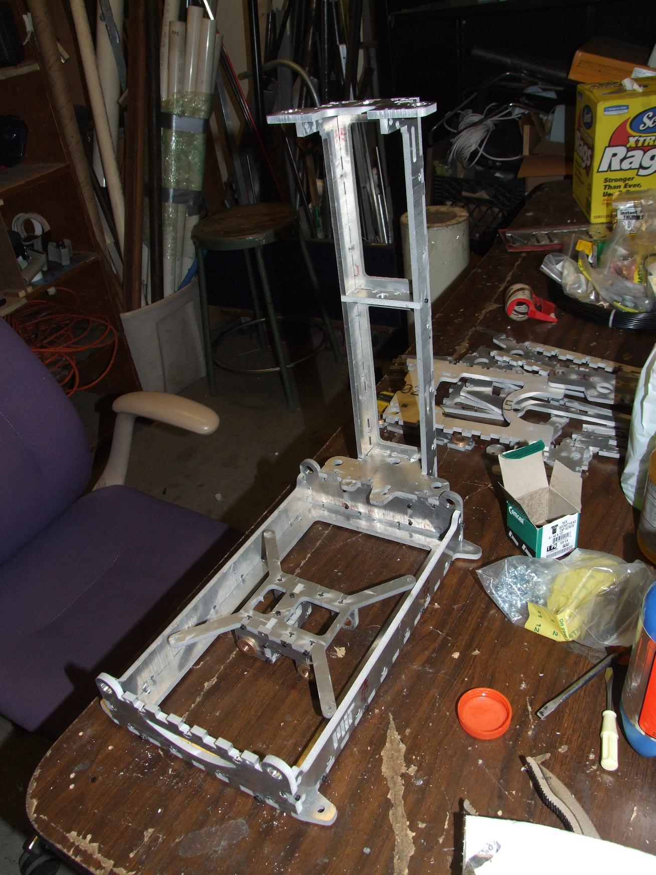
Hey, what’s this aluminum sculpture sitting in the corner here?
It’s still smiling after all these months.
Oh, that’s right… I was working on a 3d printer, wasn’t I?
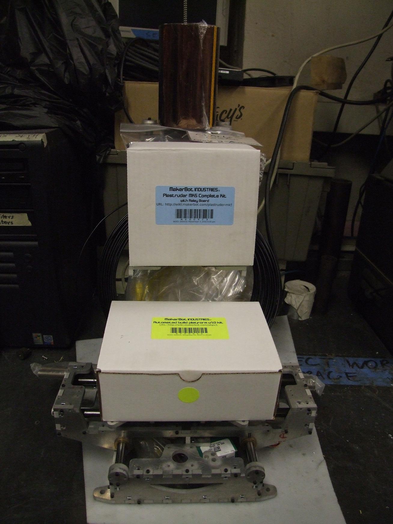
I’ve been working on Make-A-Bot in the background a little, including ordering some of the final parts needed to complete it. I purchased the ABS extruder head from the Makerbot Industries, along with all the control electronics and the cute little automated build platform. Stock equipment, but it’s equipment which they’ve figured out and which would take me longer and cause me more pain to re-engineer again. Past that, though, the last month and a half has seen little physical progress because of my other obligations – mind you, both my 2.009 work (to be detailed) and Segfault were actually for class for once. Imagine that.
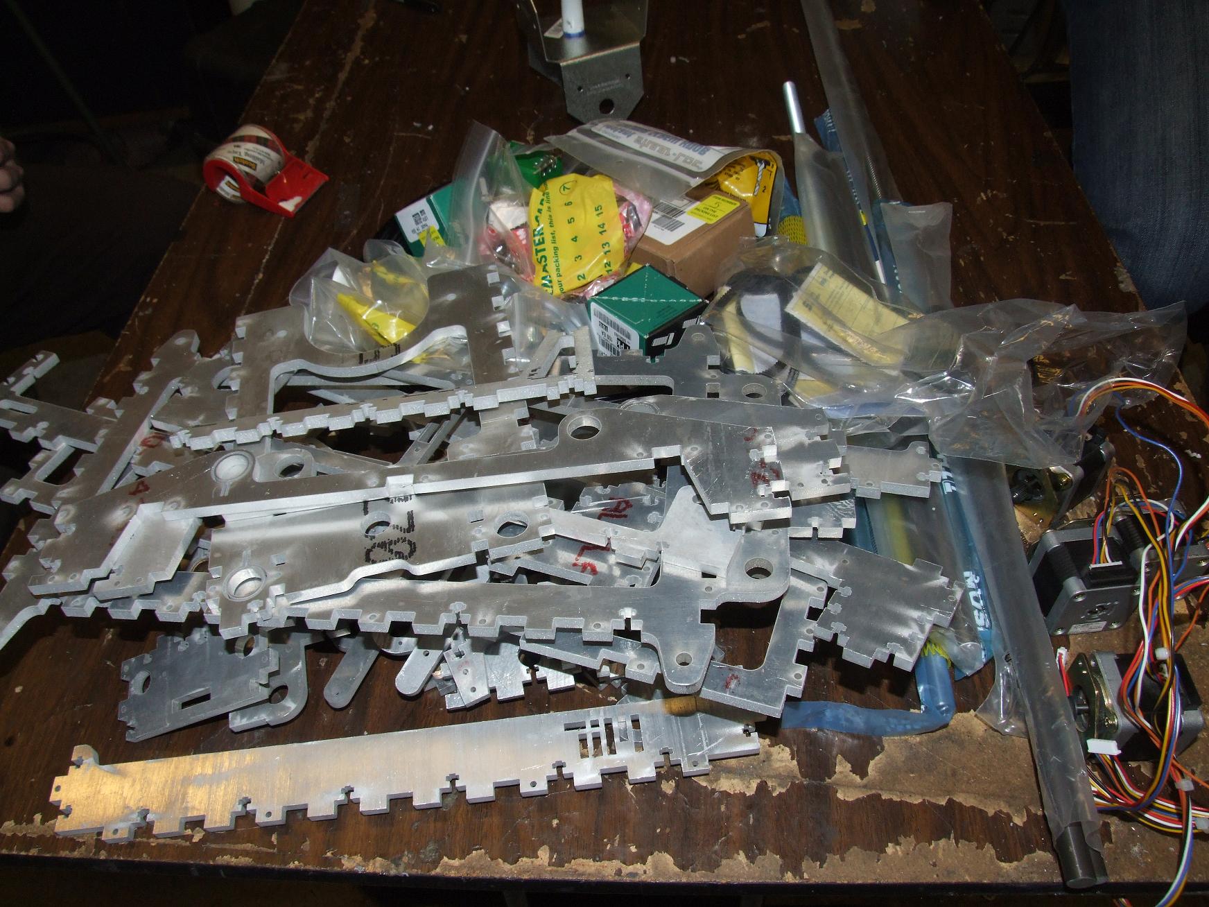
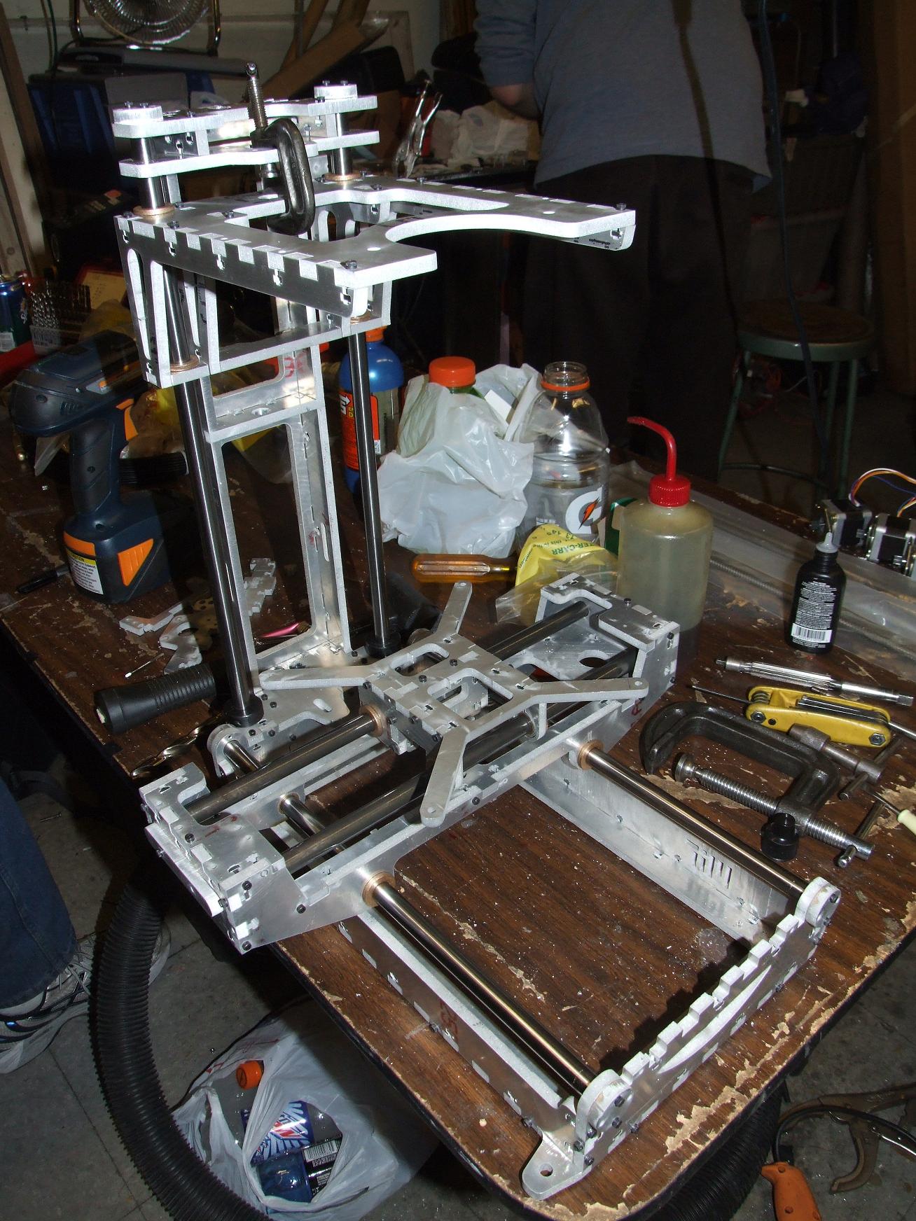
Make-A-Bot was left at a stage typical of my projects where I have built everything I designed already. That means without further design, I just have a Fancy Aluminum Sculpture. As lovely as sculpturework is at times, I’d rather have a 3d printer.
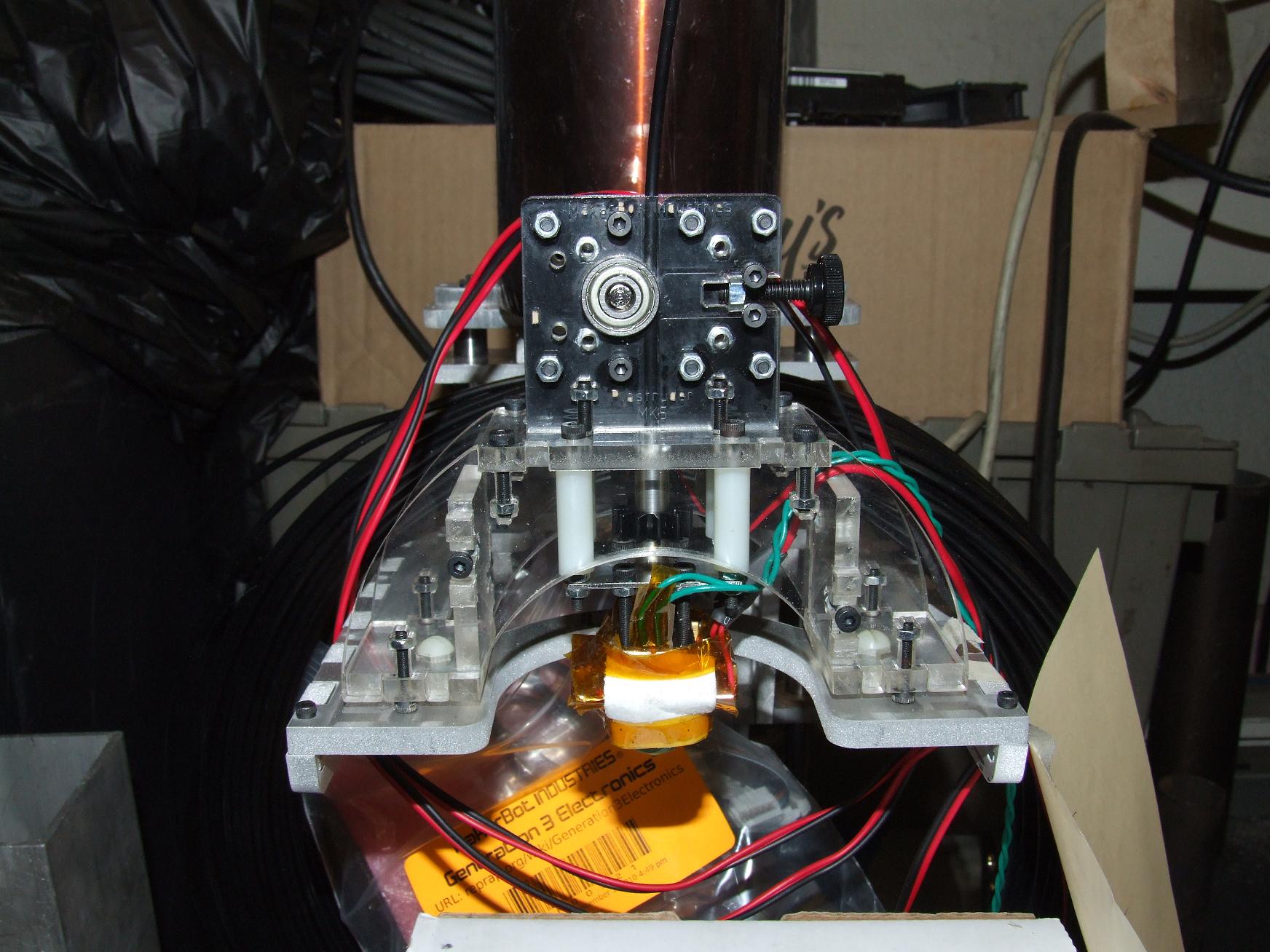
First, I put together the Plastruder 5 head for kicks. I must say, this thing is adorable and pretty intuitive to build. It is a bit bulky, though, on the motor end of things (Dear god, why such a GIGANTIC motor?). Maybe a possible direction to explore in the future. I was also a bit dissatisfied with the mounting surface, which doesn’t seem to actually have a solid mechanical connection to the rest of the head, but it could just be a consequence of me trying to adapt it to my own custom mounting configuration. A quick nylon through-bolting solved the issue anyway.
I have yet to try actually heating it to full temperature and shoving some of the ABS filament through.
Anyways, onto the designs:

How can you tell that I got a new widescreen monitor?
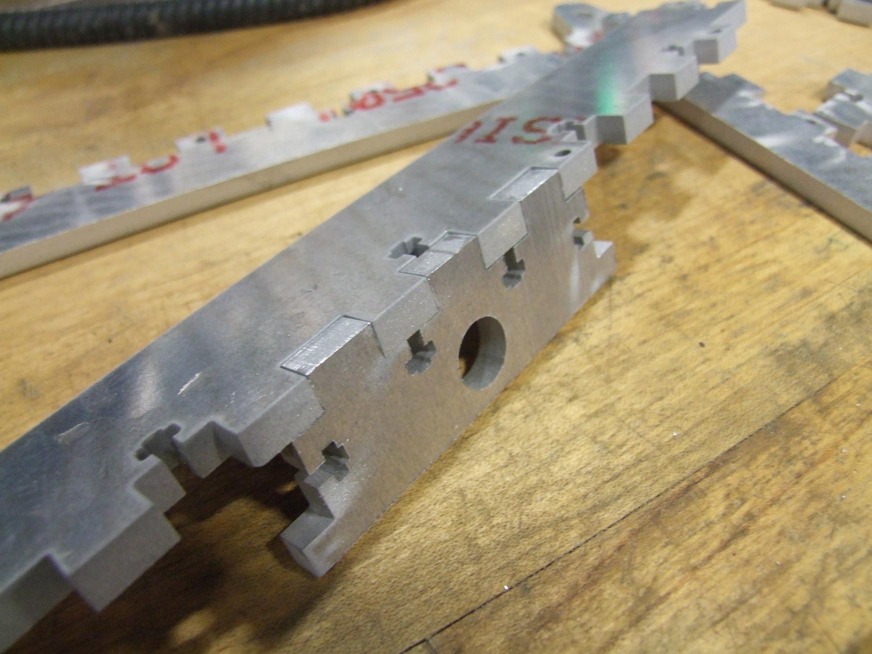
I jumped back into Inventor and started designing the support equipment cabinet that will house the feedstock filament, the power supply, and properly mount all the electronics. Without something to organize those components, MaB is just a rickety imitation of a small manual milling machine. The cabinet I designed (essentially all on-the-fly with little forethought) is actually more of a pedestal for the machine proper. Designwise, it looks like the rest of the bot with all of its edge-stitching and interspersed T-nuts. I discovered that designing panel footprints in increments of 1/2 inch made the t-nutting and edge-stitching process very fast, since the layout is always symmetric about a center line. This beats my previous tactic of calculating precise widths for the slots and tabs such that they end up symmetric. Forget that – just beasting it solves the issue, as usual. I’m fine with that.

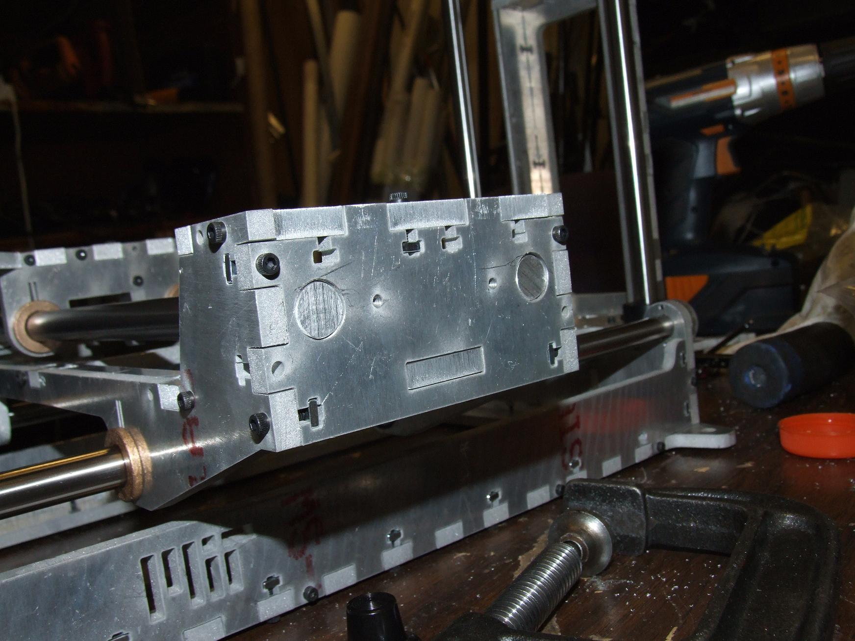
All the important electronics – three axis controllers, the motherboard, the extruder controller, and the auxilary relay board, get a home on the “backrest”. I even OCD’d enough to model (blockily, anyway) the protruding components on the boards. I lined up the important connections to face each other or be close to each other, so the wiring should end up clean. The electronics backpack also has slots and holes to pass wire through cleanly.

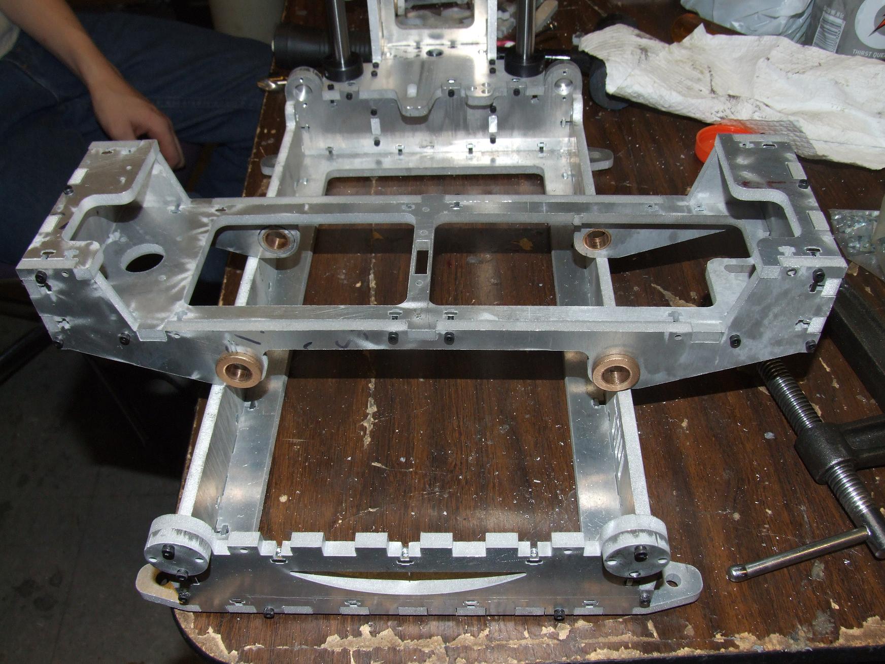
Make-A-Bot looks cute sitting on its couch-like pedestal until you realize how huge the whole thing is. That base is a full 22 by 12 inches and the top of the wooden backrest thing is 14 inches tall. Add MaB’s own height to it and this whole thing is already over 2 feet tall.

Man, this whole widescreen thing really makes my CAD screenshot proportions weird. Anyway, having purchased like 10 miles of ABS filament (which came in a massive donut-shaped coil), I decided I needed a method of keeping it all in line so I don’t have to constantly feed the filament. Makerbot does sell a spindle kit for such an occasion, but this was one part I decided to just tackle myself.
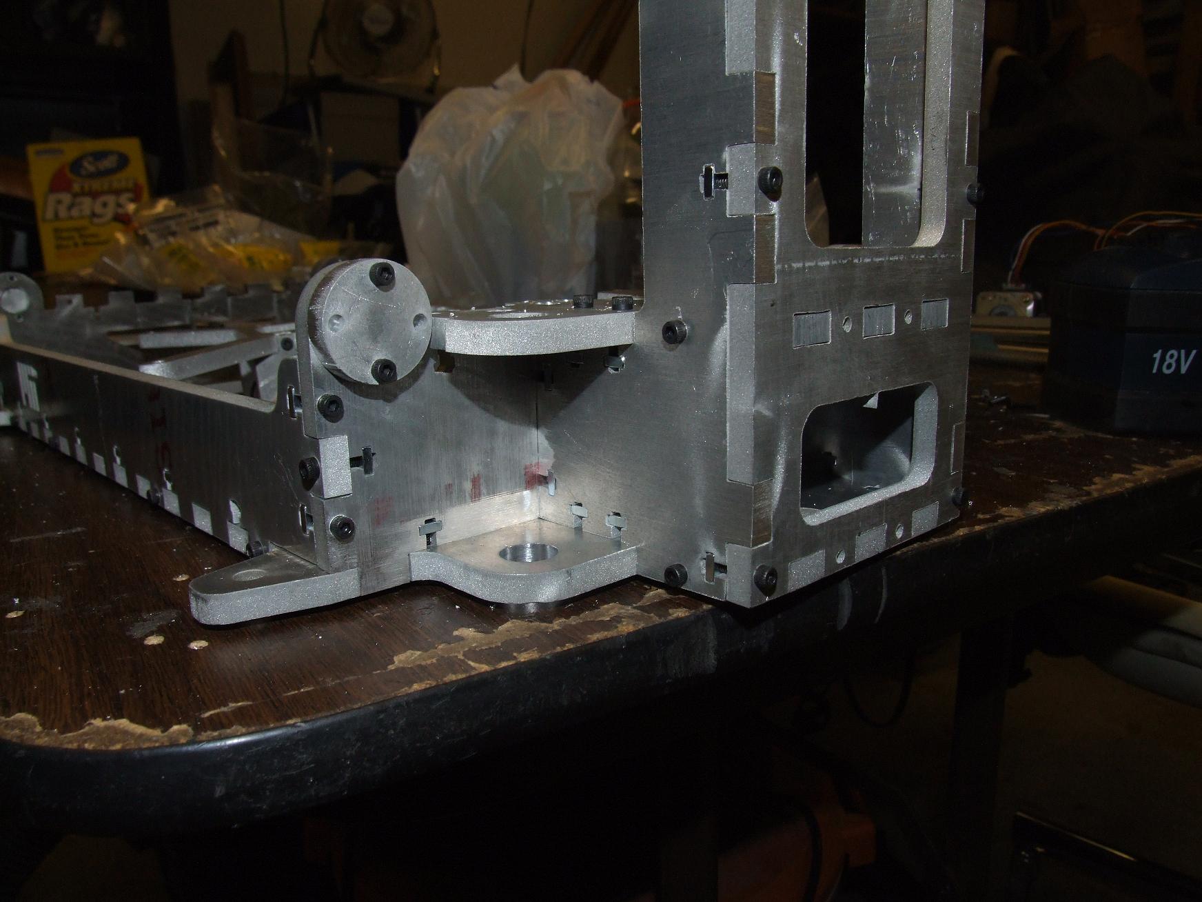
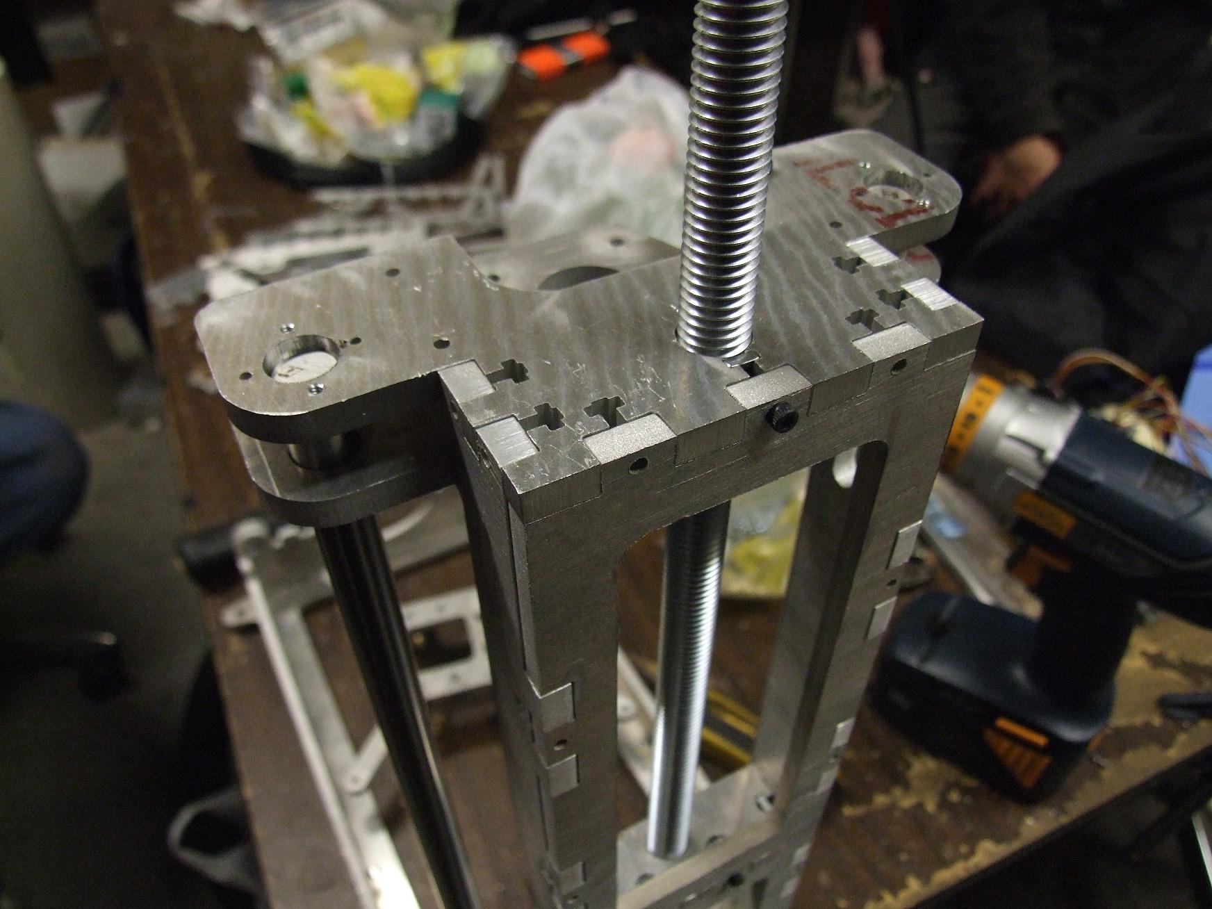
Above is the filament spindle design. There’s a truss piece under the top triangle shaped plate which holds the vertical spars together. The top plate can come completely off for filament changing, but otherwise has provisions for a detent-lock effect supplied by the vertical spars and a few degrees of rotation. It will all become clear after the fabricated pieces are assembled.
People prone to vertigo should avert their eyes:

Come on into THE VOID.
What’s THAT?
Over the course of a few days of on and off thought, I decided that I’m not going to run the automatic build surface. I’ve come to dislike the bed-type design I settled on for MaB 1.0 (Yeah – I’m already thinking about what 2.0 will be like!). Such a design is great for applications where the machine is many orders of magnitude heavier than the workpiece usually is – like most milling machines. When this is not the case, a changing workpiece weight can affect the dynamics of the machine greatly. A moving work surface also puts force on the workpiece when it accelerates. The axis inertia is much greater and also mismatched because one axis must be installed on the other (i.e. in my case, the X platform is mounted on the Y carriage). Therefore, MaB 2.0 will be an overhead gantry type machine with an fixed work surface that only changes in Z height to print layers.
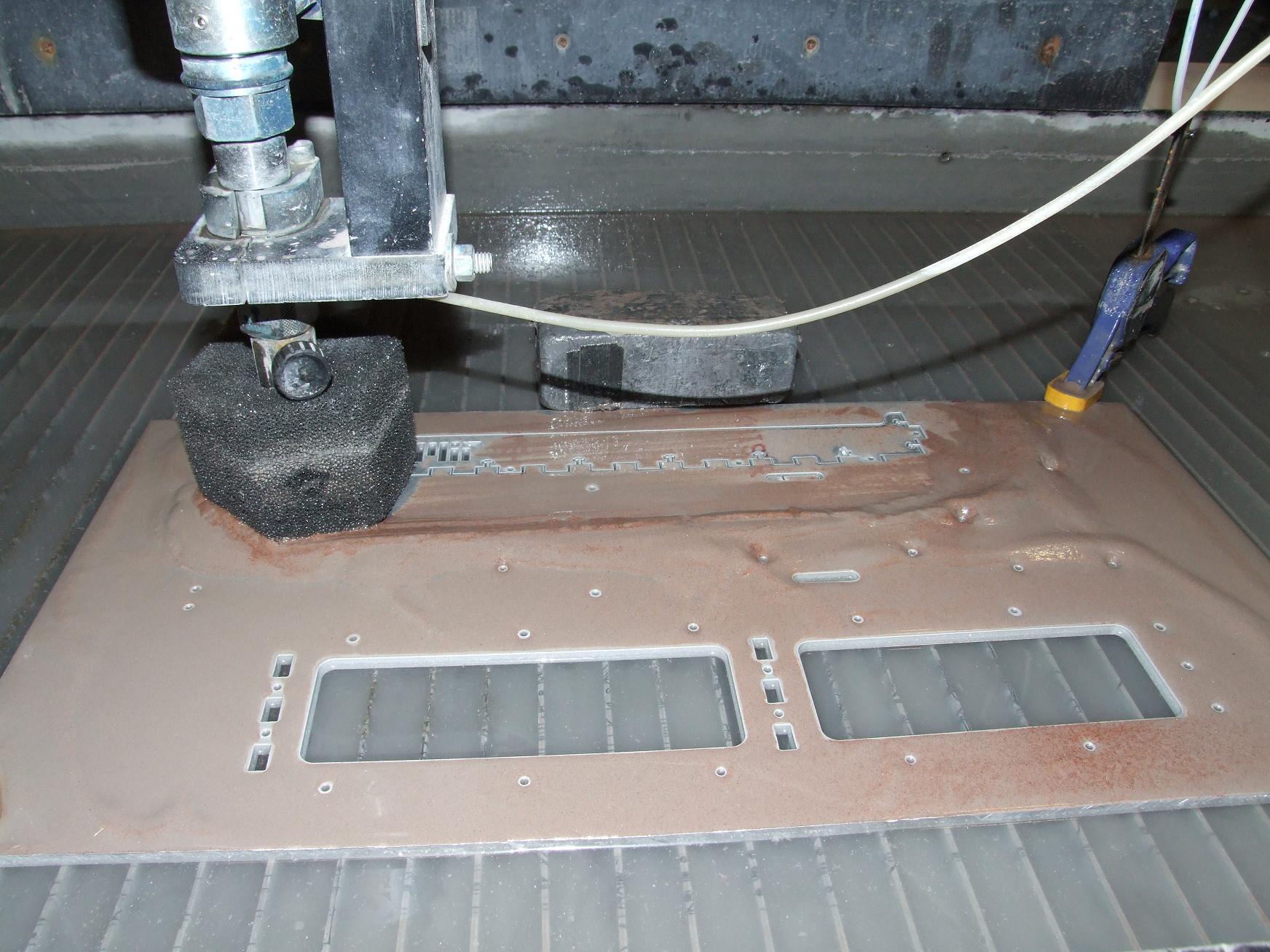
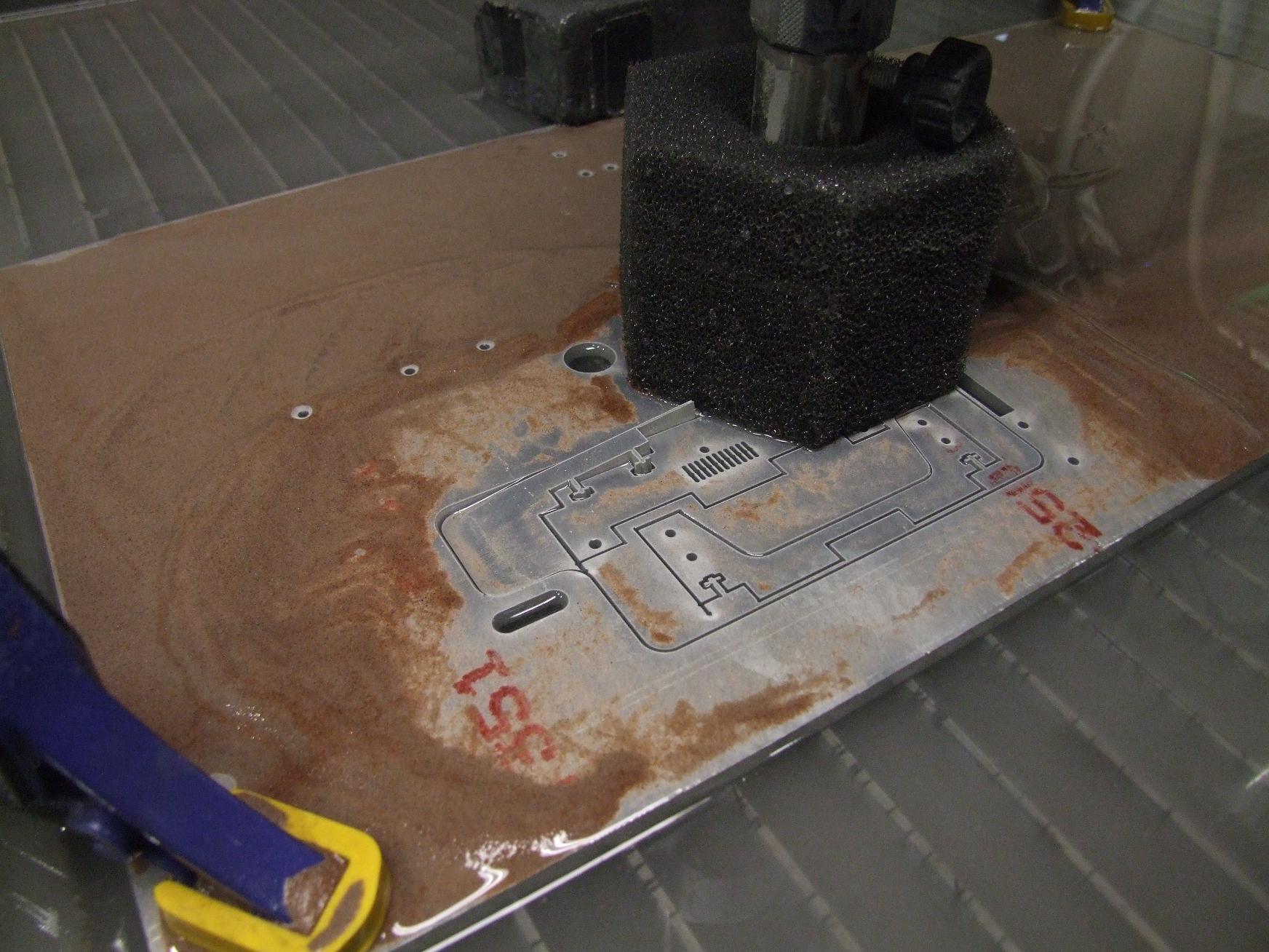
What on earth does that have to do with the trippy-ass PCB up there? Well, that PCB is just my take on the Makerbot Heated Build Platform. For now, I’ll just keep the surroundings of the workpiece nice and warm. I really don’t mind limiting myself to one thing at a time. It’s just a little bigger than the stock part. And by a little I mean it’s 7 inches square and designed for 50 watts of heating power. It took a while and even more OCD to get those trace lengths correct. There will be a thin aluminum plate thermal-transfer-epoxy mounted to the center heating coil section (not bolted down, but legitimately adhered with silver-bearing epoxy).
This piece is reusable in any future MaB versions since it’s already pretty substantial in terms of square inchage.
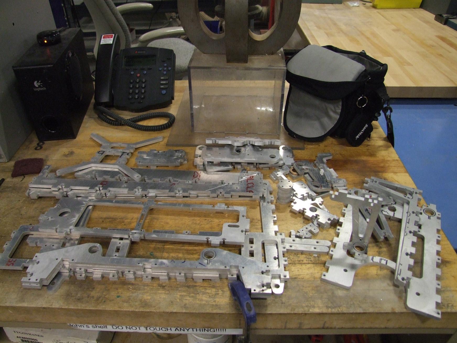
making the makings of the make-a-bot
After designing, the next step is of course for me to build have expensive computer controlled machinery build it all. Spoiled so much I am…
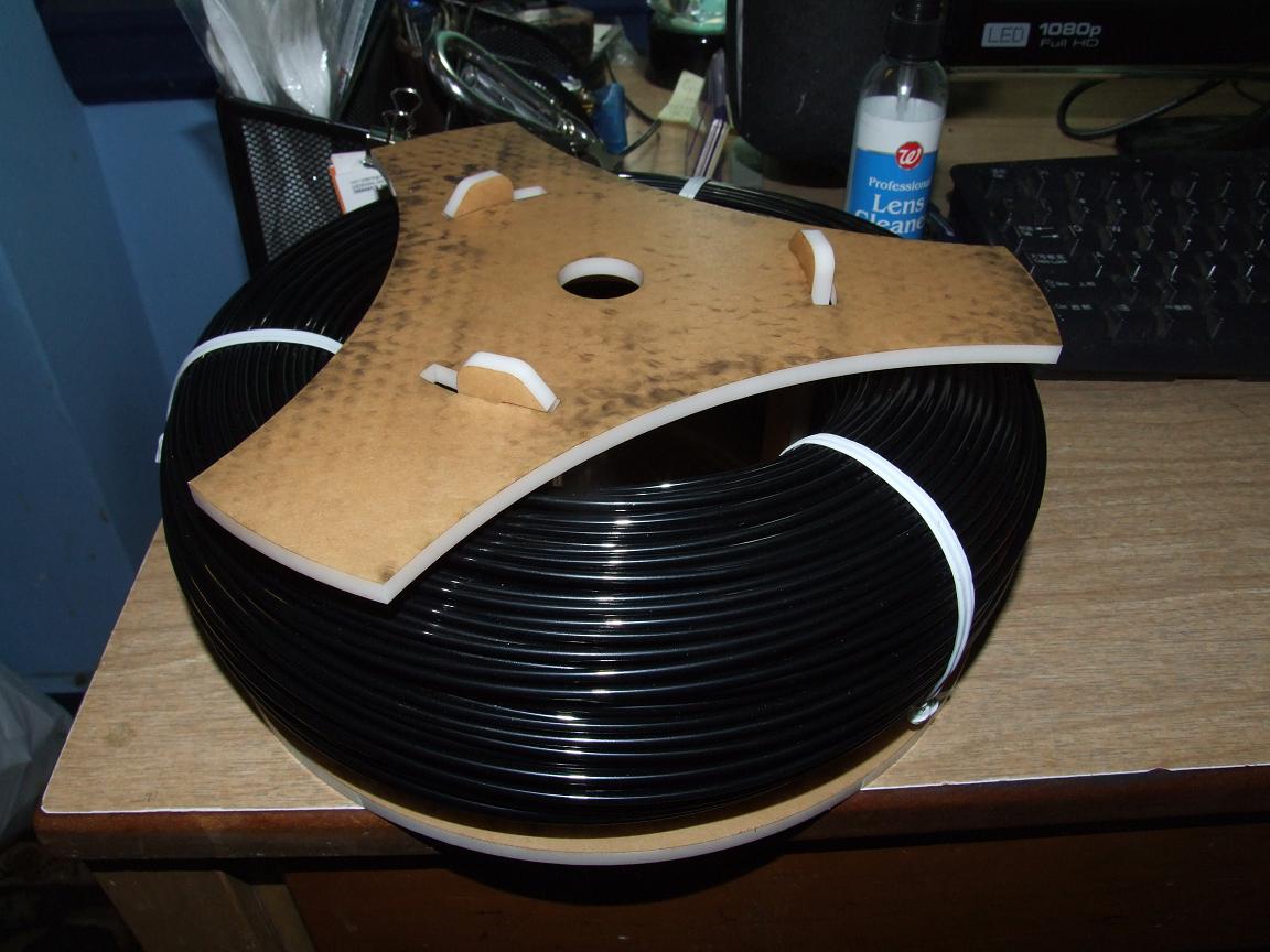
Here’s the spindle laser-cut from 6mm white acrylic that I had on standby, holding the Giant ABS Donut. You can see the click-lock fingers easier in this picture. To unlock, rotate a few degrees counter-clockwise and then lift up. To lock again, drop the top plate over the 3 prongs and twist clockwise. This system turned out great. I can actually add a few thousandths more “click” to the prongs, since the laser cutter kerf removed most of my designed interference.
And now, for something completely different:
Hey, what kind of wood is that?
Long story short, I thought there were large stocks of 1/4″ hardwood ply hanging out around the Media Lab – our group usually has a pile for making quick prototypes and displays – but alas, it had been run out and not yet replenished. Not knowing where we got the wood from, I just went ahead and plucked some acrylic panels from McMaster. Acrylic, wood, same thing, right?
I elected to get tinted panels this time to try out the looks, along with plain clear panels.
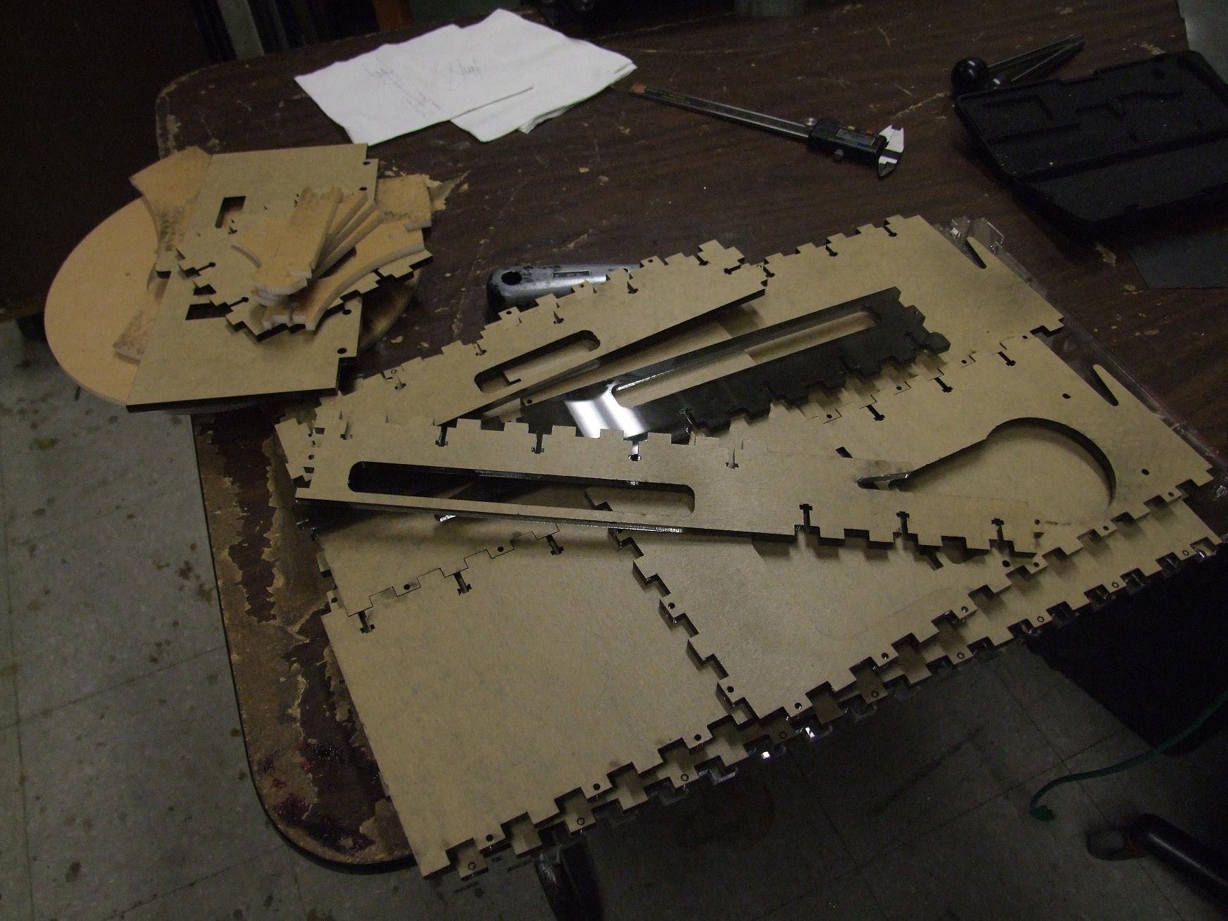
The next step was to pitch it all on the laser cutter wake up in time to run to the shop before it closes and laser-cut everything. This actually took a long time, as in several days of preparation and missed (and actively suppressed) alarms; as soon as term ended, I immediately restabilized to my 9-to-5 sleep schedule. Yes, my day job is sleeping. Take that, industry. It does make interacting with a shop that is open from roughly 9 to 5 difficult.
I am, however, very glad I went with acrylic:
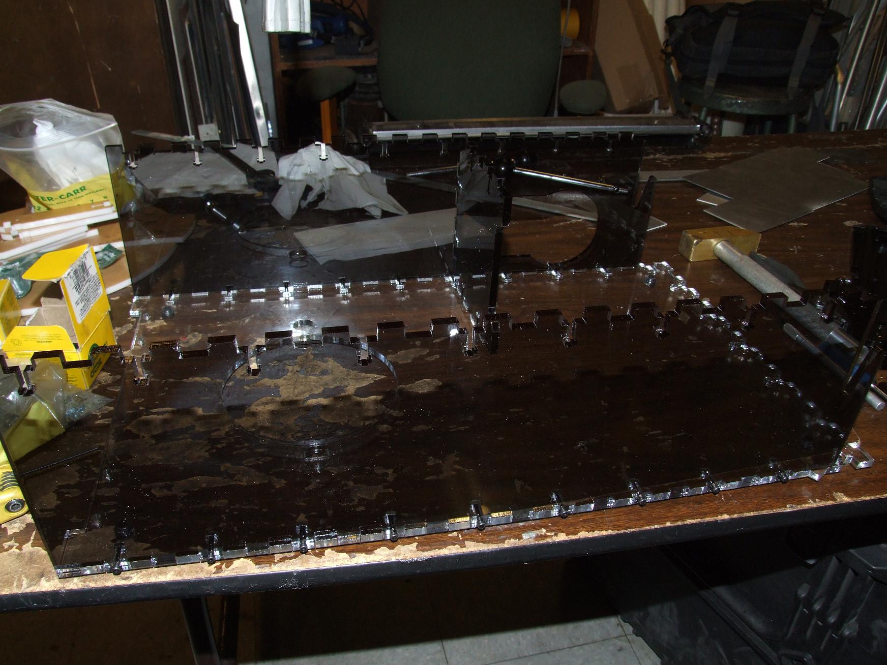
Let the case mod begin. My favorite part of building things is always the case mod – what can I make unnecessarily shiny, backlit, glowy, and translucent?
I made the base out of clear acrylic and the sides (and everything else) from the tinted stock. It created some unexpected contrast that I enjoy alot.
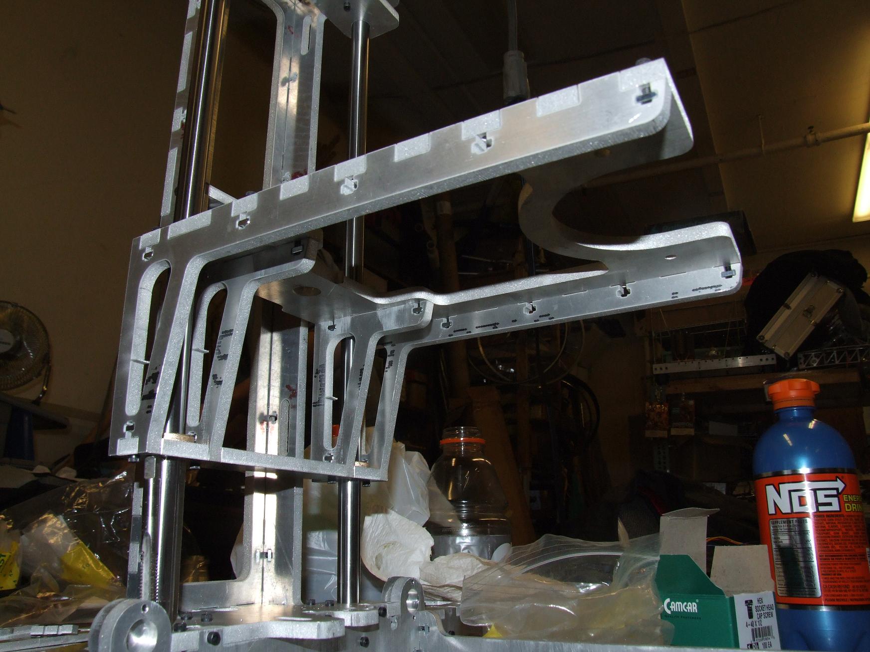
The L-shaped side plates were split in two for more convenient cutting. Since the “electronics backpack” is not supposed to bear structural loads, I just joined the two legs of the L with a ninja-tail (not quite a dovetail). The “backpack” portion drops down from above after being pre-assembled and is secured by requisite t-nuts.
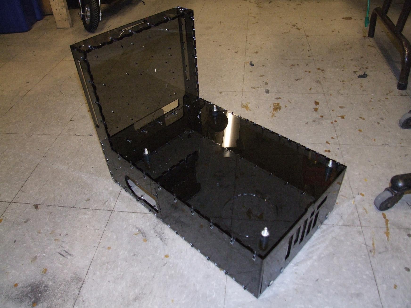
The completed pedestal. Hey, if nothing else, MaB can be turned into a absolutely beastly PC. There’s even a cutout for an ATX power supply already.
Oh, so that’s what the A in Course II-A stands for.
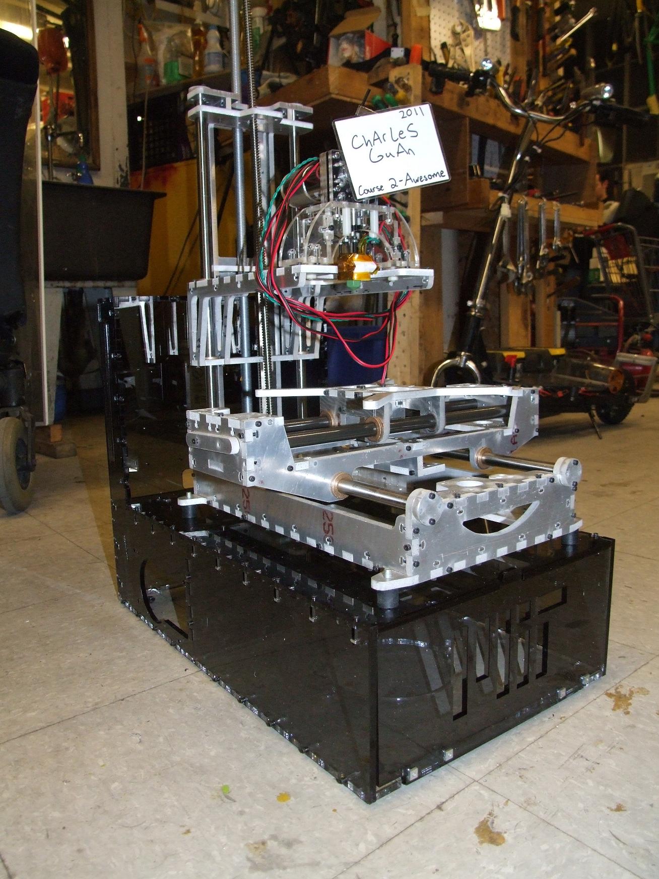
And the moment of truth – does it actually support the machine weight?! Curse me for building a contactless tool out of heavy \m/etal.
Make-a-Bot itself sits on four little rubber shock mounts. They weren’t necessary, but I figured they were worth including anyway.
I think the design looks gorgeous. The glossy tinted sides complement the raw metal components well, and should look even better once I have some internal mood lighting.
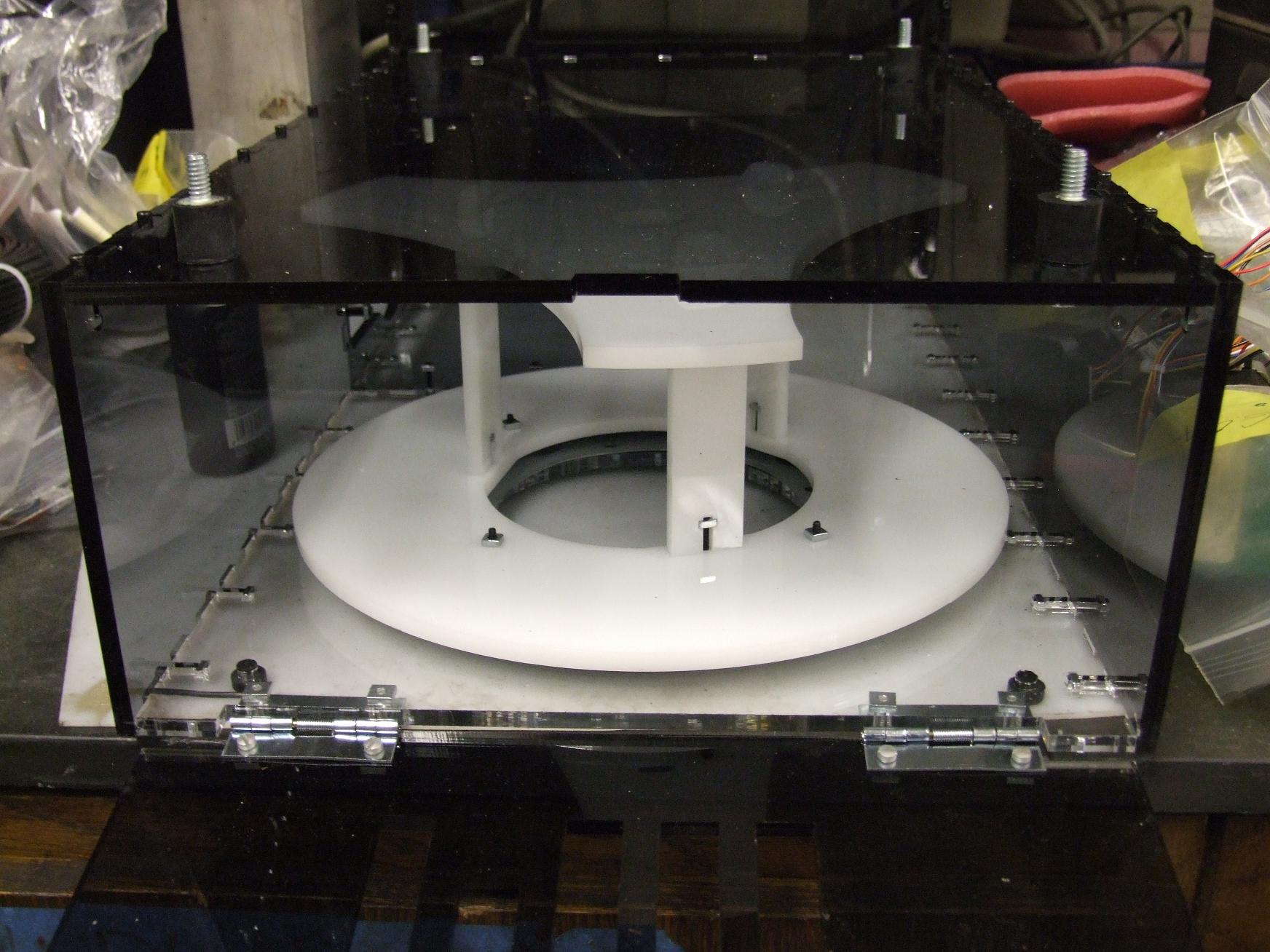
Previously unknown fact: The spindle sits on a large 9″ diameter turntable bearing. This allows the extruder head to tug on the filament at its leisure. The bottom of the turntable bearing is not fixed to the machine. It just kind of sits there – this is not exactly a heavily loaded or high speed application here.
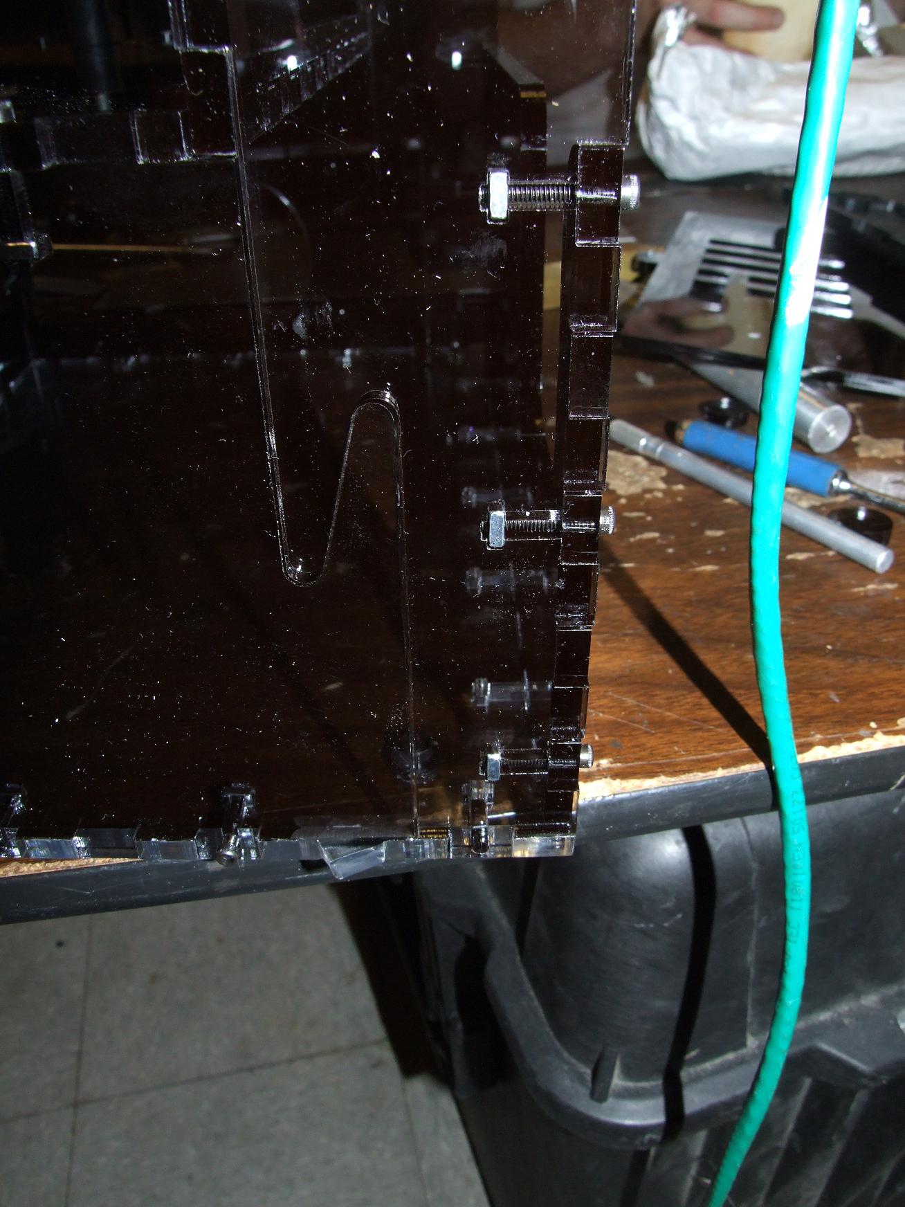
Oh, another detail: Check out the spring-loaded front lid that drops down for easy filament removal. When the lid is opened, its own weight keeps the hinges down, but when it’s vertical, there’s enough force to keep the whole thing closed.
As many random features as I’m putting on this thing you’d think I’m intending on making a production version or something. Not really, but I hope designers of commercial kit machines find some of these aspects helpful.
srs metal
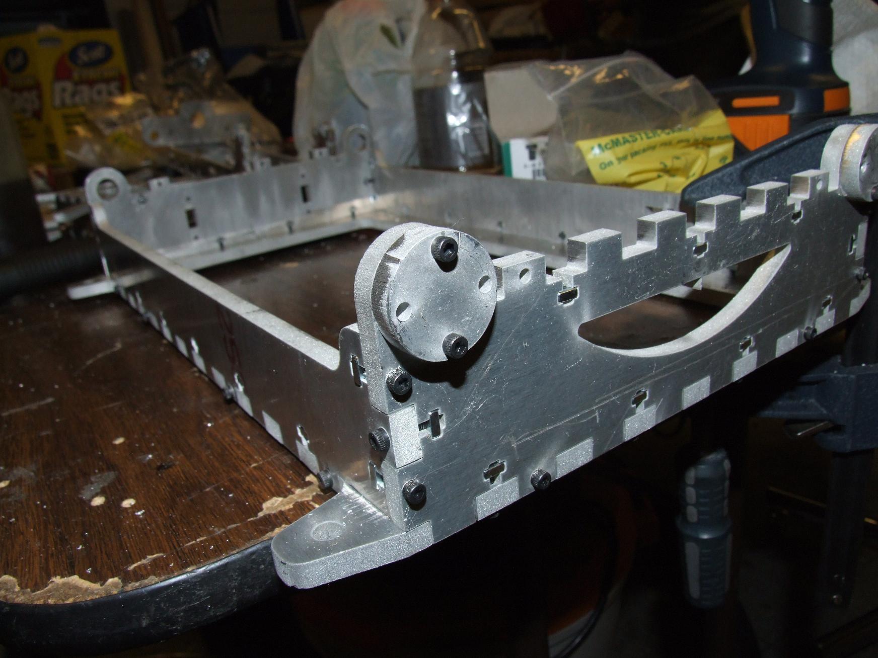
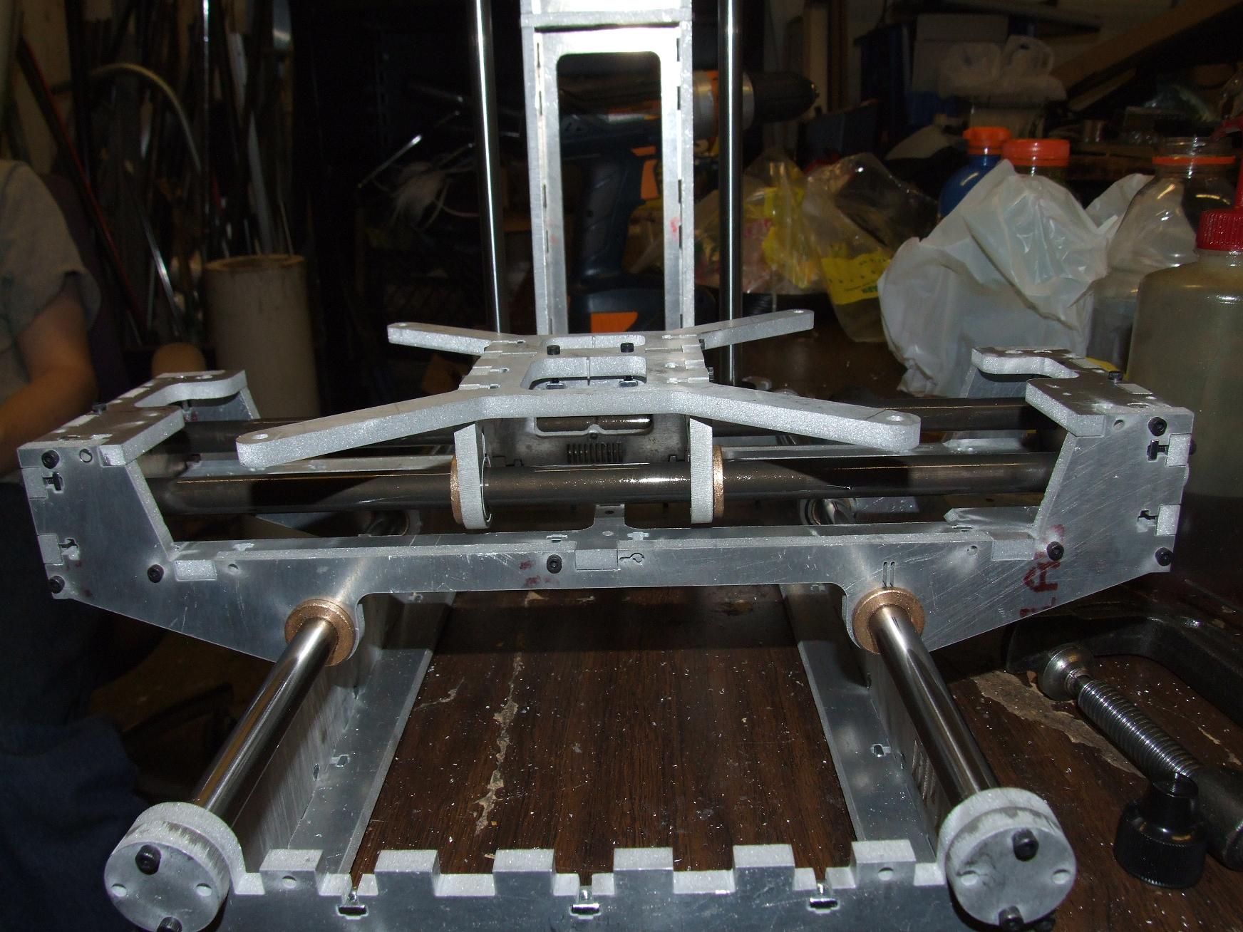
With the pedestal completed, I turned my attention to back to the machine itself. It still didn’t have the steppers installed or the axis belts mounted yet. I decided to tackle that problem first.
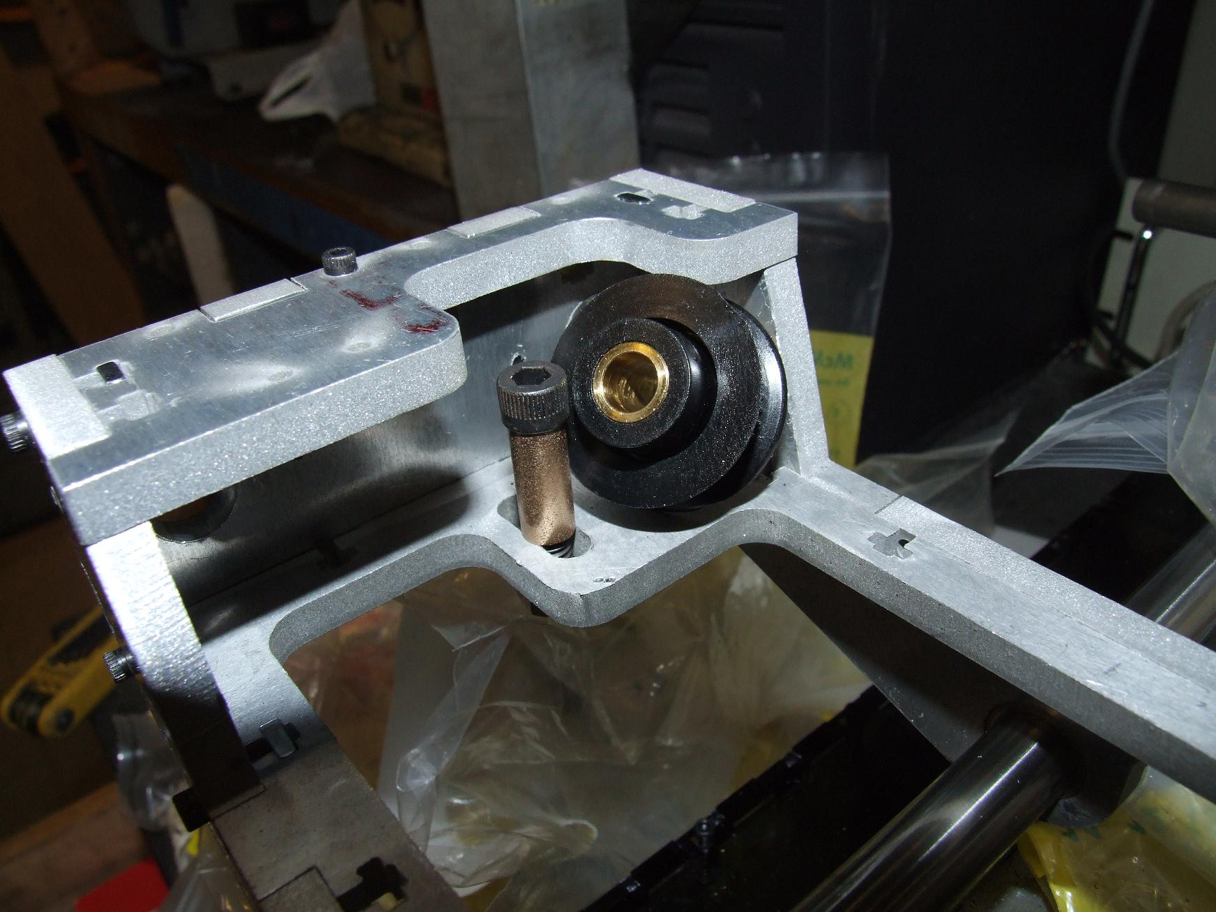
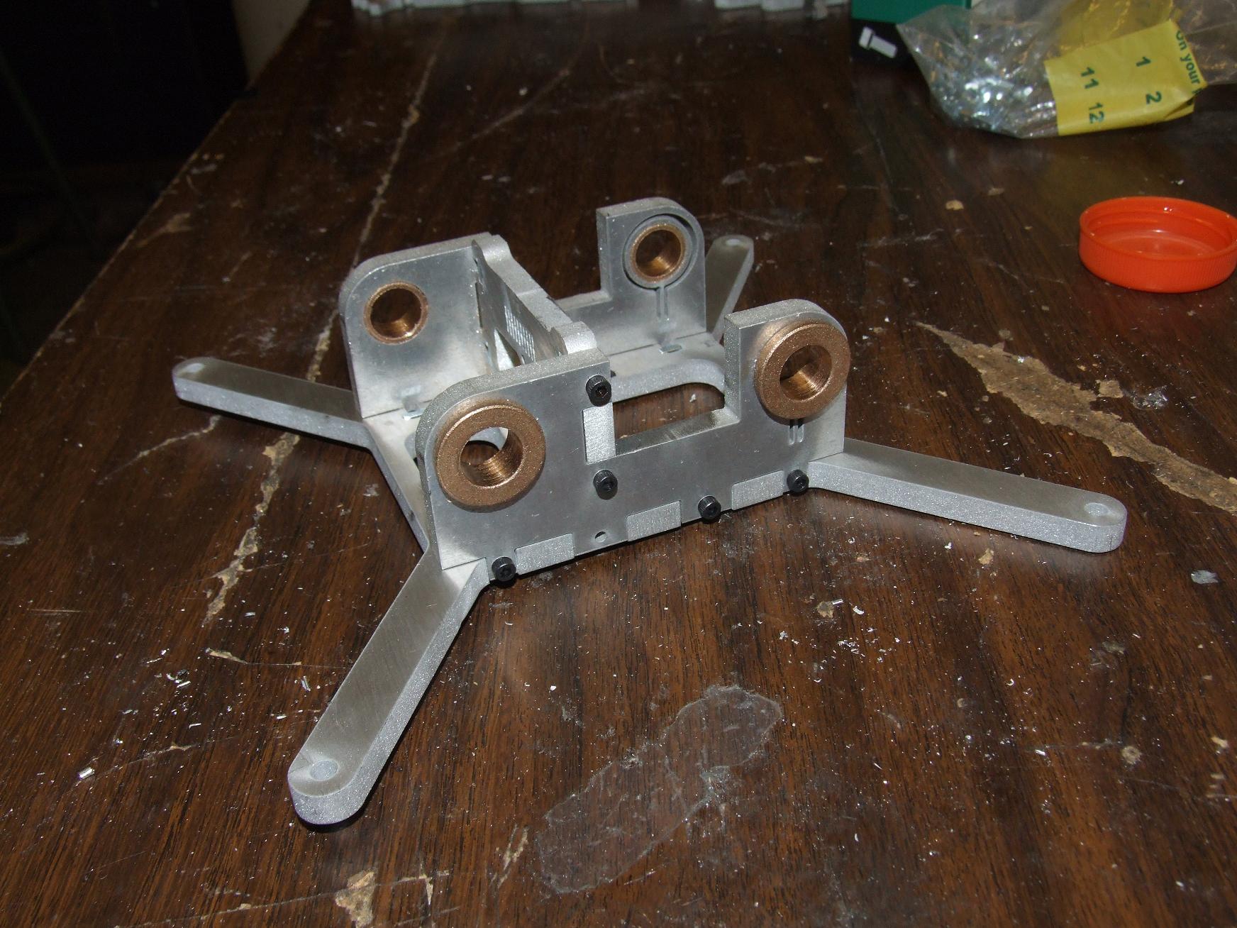
The pulleys came with a 5/16″ machined brass bore that by itself is an okay bearing surface for low speeds. I would have just put it on a 5/16″ smooth precision shoulder screw, but could not find one around that was long enough.
Solution? Mock one up from a 1/4″ bore, 5/16″ OD bronze oil bushing and a 1/4″-20 cap screw. The cap screw uses the bushing as a standoff of sorts and a nut keeps the whole thing rigid.
With a few drops of teflon-infused oil at the interface, the glide is almost as smooth as greased ball bearings. Being a millimeter or two longer than the pulley bore, the bronze bushing allows for smooth pulley rotation without much regard to how hard the screw is tightened.
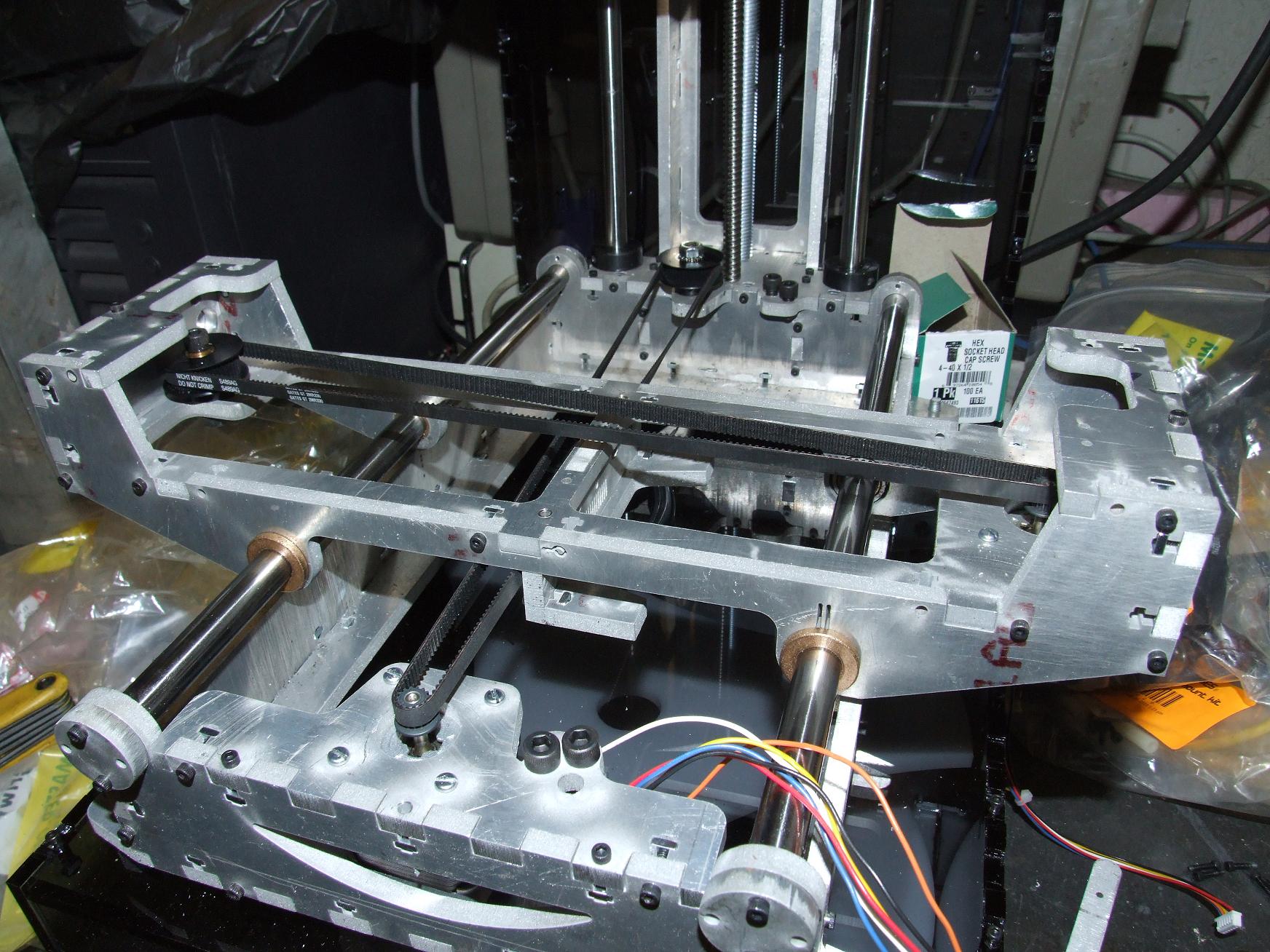
The steppers I ordered came with 15 tooth 2mm GT pulleys already installed on their shafts. So why bother changing them out to the stock 17 tooth ones? The smaller pulley gets me more force anyway.
I should be able to adjust the machine travel-per-step in software.
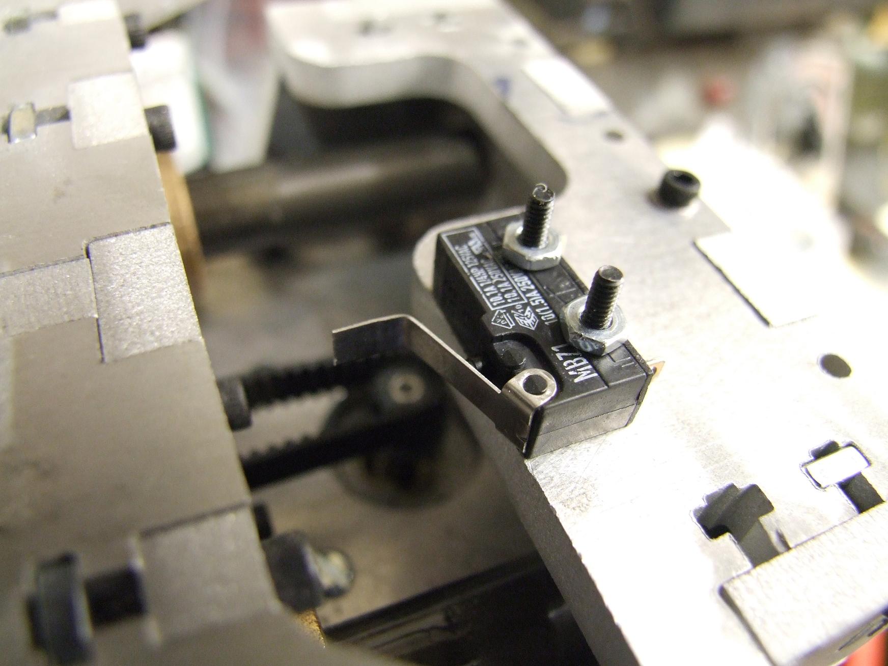
Every elegant engineering solution has a complementary ugly hack. Remember my Awesome Adjustable X-Axis Endstops?
When I become ambivalent and lazy, they become Dude, You Just Bent The Existing Contact Arm On The Switch A Little X-Axis Endstops.
Hey, it works.
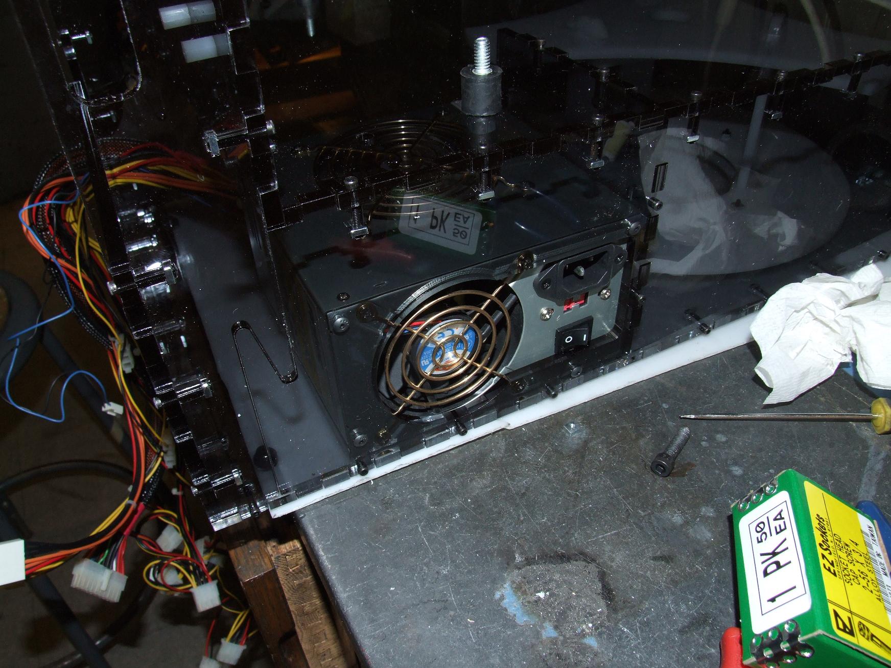
The ATX power supply has its own cubby at the back of the pedestal. The bright polished brass between the dark acrylic makes the whole thing look classy.

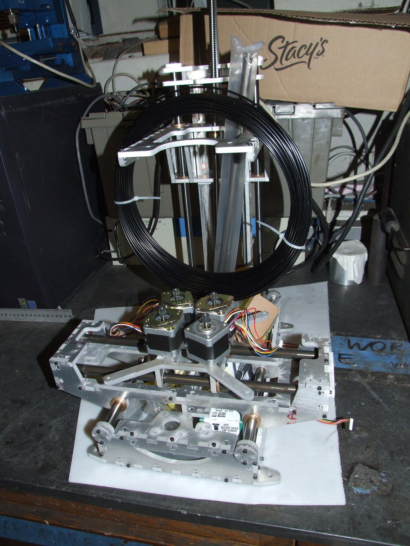
And everything as of now. I’ve attached the axes to their respective belts, and they feel alright. No obvious jamming or tight spots, though I still don’t like the X-axis ceramic-coated rods. Important mechanics left include the attachment of the other limit switches and attaching the Z-axis leadscrew to the stepper motor. After that, I should be able to run an all-axes motion test!