With RazEr, LOLrioKart, and my fleet of deathbots, I have on occasion received jibes that my entire engineering career is in fact an elaborate suicide plot.
The reasoning is that since everything I build is by nature harmful to one’s physical health in some way, one of my projects will eventually do me in – especially as I escalate the level of engineering and complexity (and power) involved with each. And because I am purposefully doing so, I MUST be trying to kill myself actively!
Well, sadly enough, I hope I won’t prove all of you right, but check out my latest creation!

…
Just kidding. I would NEVER build such a thing (blame the other Chinese), nor use it. I mean, come on. It’s gas powered. How lame as shit is that?
I would never stoop that low. But, for the longest time now, I have indeed wanted to build motorized skates. Only problem? I can’t skate.
The only maneuvers I can perform on skates (ice, ball bearings, or otherwise) is “accelerate forward and maintain constant forward velocity”. Note that says nothing about stopping, reversing, or even turning. Like in racing games, that’s what walls and other people are for.
So why on earth do I want to build motorized skates? Because they’re awesome, that’s why. I thought more about this prospective build after I perfected the version 1 wheelmotor. It wasn’t until version 2, though, that the idea was actually within the realm of practicality, for version 1 lacked meaningful amounts of torque.
Version 2 survived for about a year and a half before too many curbhops stripped the case screws and trashed the bearings. I have yet to rebuild it, or for that matter, build any new hub motor, due to other project commitments and the curse of “OK IT WORKS TIME TO MOVE ON”.
Last year, though, I got a free set of Rollerblade (yes, real Rollerblades made by the Rollerblade company) from someone who I presume was going to try and motorize them, but stopped short of actually making modifications.


They look like they’re a decade or two old and are well used, but not beat to shit. Perhaps “well loved” is the better term here. The wheel frame has its fair share of scuffs and scratches, as does the boot, but nothing’s broken. The wheels, though, are nice and cone shaped from what I can only assume is daily recreational use.
I pretty much dropped them off at MITERS immediately afterwards and didn’t look at them again until now. The whole “well, even if I did build them, I’d not be able to actually use them” thing kind of took my mind off the project. But they became background processes. I’d occasionally entertain the thought of actually building them, but wasn’t confident that smaller wheels (in the 70 to 80mm range, as found on most inline skates) could actually move a person. This was before I knew as much about BLDC motors as I do now.
Air Treks
A little known fact about the Version 2 wheelmotor and RazEr is that the single strongest source of attention to the project is the anime and manga community. Why? Because of a semi-popular series called Air Gear, which is a shonen manga and associated anime revolving around (mildly magical) skate-like inventions, which use… of all things, in-wheel something motors. I don’t know if they’re supposed to be electric or black hole powered or what. Apparently, the point of these Air Treks, as they are called, are to make you fly and see cool shit nobody else can see.
Right. But as with any successful series, there are cosplayers and enthusiasts who dress like the characters in the show. Yours Truly has dabbled in this to a degree, and makes a halfway decent L. Out of an almost morbid curiosity, I watched a few episodes of Air Gear.
It’s Dragon Ball Z and Tony Hawk Pro Skater 2’s illegitimate offspring.
Regardless, being constantly bombarded with emails and messages about the secret of Razer, it’s rekindled interest in the project. If I can’t use my own creation effectively, why can’t someone else try? And so I made a few more sports-inclined friends sign their lives away to be my crash test dummies test pilots.
Thus, I made the first forays to investigate the feasibility of hub-motored skates. The project has been temporarily designated Deathblades, because what else can you possibly do on a set of these besides give yourself severe, possibly terminal head trauma?
The Gist
Let’s continue. I excavated (almost literally – it was buried under a year of accumulated cruft) the box of skates from MITERS and started picking them apart.

Luckily for me, the wheel frames come right off. This suddenly just got alot easier. As long as I have the plastic boot with its hardpoints, I can attach fucking jetpacks to the frames if I wan….
… Okay, back up. That’s just a HORRIBLE idea. I’m going to pretend that never happened.
So, the wheels are off, the frames are off, it’s 5 in the morning and I have no sanity to speak of. Let’s start digging for possible parts!

I unearthed all of my Random Small Copier Motors. This is the collective hearts of maybe 5 laser copiers. I have more, but those motors are substantially larger – in fact, a HUGE Xerox motor became the core of Wheelmotor version 2.
All of these things should have stators in the 50 to 55mm diameter range.
I hoped to find at least four matching or quasi-matching ones. Why? Two motors of this size aren’t going to output enough torque to move any meaningful weight around, especially direct drive.
Plus, 4 wheel drive skates. Four wheel drive skates. If I was going to do it, it might as well be good.

I butchered the copier motors and started playing the mix and match game.
The bottom line: I have three stators of identical dimensions, two of the same diameter but identical shorter lengths, and two that match eachother but nothing else, but only by like 1mm difference.

Because I’d have to use different magnet can arrangements if the stator diameters were different, I decided to keep these four around for the time being. They are all identical diameters, but two are 5mm shorter.
This isn’t a dealbreaker, because brushless motors roughly obey a law not unlike a first order Taylor polynomial. With a given motor, you can linearly scale characteristics to a certain point to design another motor. The 5mm short stators will just need some more windings to achieve essentially same torque and back EMF characteristics as the thicker motors, but the overall power output ability will be affected.

These stators are 50.5mm diameter…


…and either 19mm or 14mm long.
Not bad.
I haven’t spec’d out wheel candidates yet, but I presume they will be modified (hollowed out) skate wheels. Wheelmotor Version 2 uses a cored out 125mm skate wheel.
At the point, I don’t expect Deathblade to use 125mm wheels, which seem to be reserved for speedskating, and are also hard to find. The original wheels on the Bravoblade GLX skates are 78mm, and the largest “recreational general purpose” wheel size appears to be 100mm.
Standard Razor scooter wheels are 98mm and seem to feature a moderately large inner diameter, which makes them good candidates. Many people around here own Razors to putz around campus, so I can probably obtain engineering samples from the next floor up or something.
I expect that a 50mm motor will probably have 65mm or larger outer diameter when the can is finished. The 70mm stator in Wheelmotor ver. 2 has a 85mm can OD.

After motor and wheel wanking, I decided to actually measure the mounting provisions on the skates. The stock wheel frames have a rectangular boss that has a threaded insert inside, which fastens to the boot with a Big Machine Screw. That’s easy to duplicate. With some caliper tricks, I got the following dimensions:
- 188mm center to center
- 24.25 long x 38.5mm wide rectangular boss, 4mm deep
- 12.5mm height offset between front and rear
Substantially simpler than I had imagined. It’ll not be challenging to machine mounting provisions directly into the replacement wheel frames. The above illustration is for reference only and isn’t part of any design.
So what’s the anticipated final look and layout of Deathblade?
I imagine it looking kind of like aggressive inline skates with a lift kit. I anticipate not using center wheels such that the skates only have 4 wheels and all are driving. The former center wheel volume will be used to house a battery pack and control electronics. The wheelbase will probably be no more than 13 to 14 inches.

Kind of like that, probably not as fancy, and with wires sticking out dangerously everywhere.
Speaking of control electronics, how the hell do I simultaneously control two foot trolleys of death? Wired is out of the question. Historical motorskate ideas have used a wired speed control with a hand trigger type setup.
I’d have to replicate the function of this hand trigger, but make it control two sides. Luckily, one thing that iRobot taught me this past summer is that XBEE radios are good things. These 2.4Ghz transceiver modules come with a built in Atmel microcontroller running the RF frontend and can be programmed through Digi’s AWESOME HARDWARE CONFIGURATION GUI to perform simple digital IO without writing code.
If there’s anything that I hate doing, it’s writing code.
They can be trained to listen to one, or to eachother. One radio in hand transmitting, and one in each foot taking commands.
For actual motor control, I might start out experimenting with R/C brushless controllers, but ultimately, due to the desire for low speed stability and the need to control torque, I’ll probably try running a variant of Face Vector Modulation.
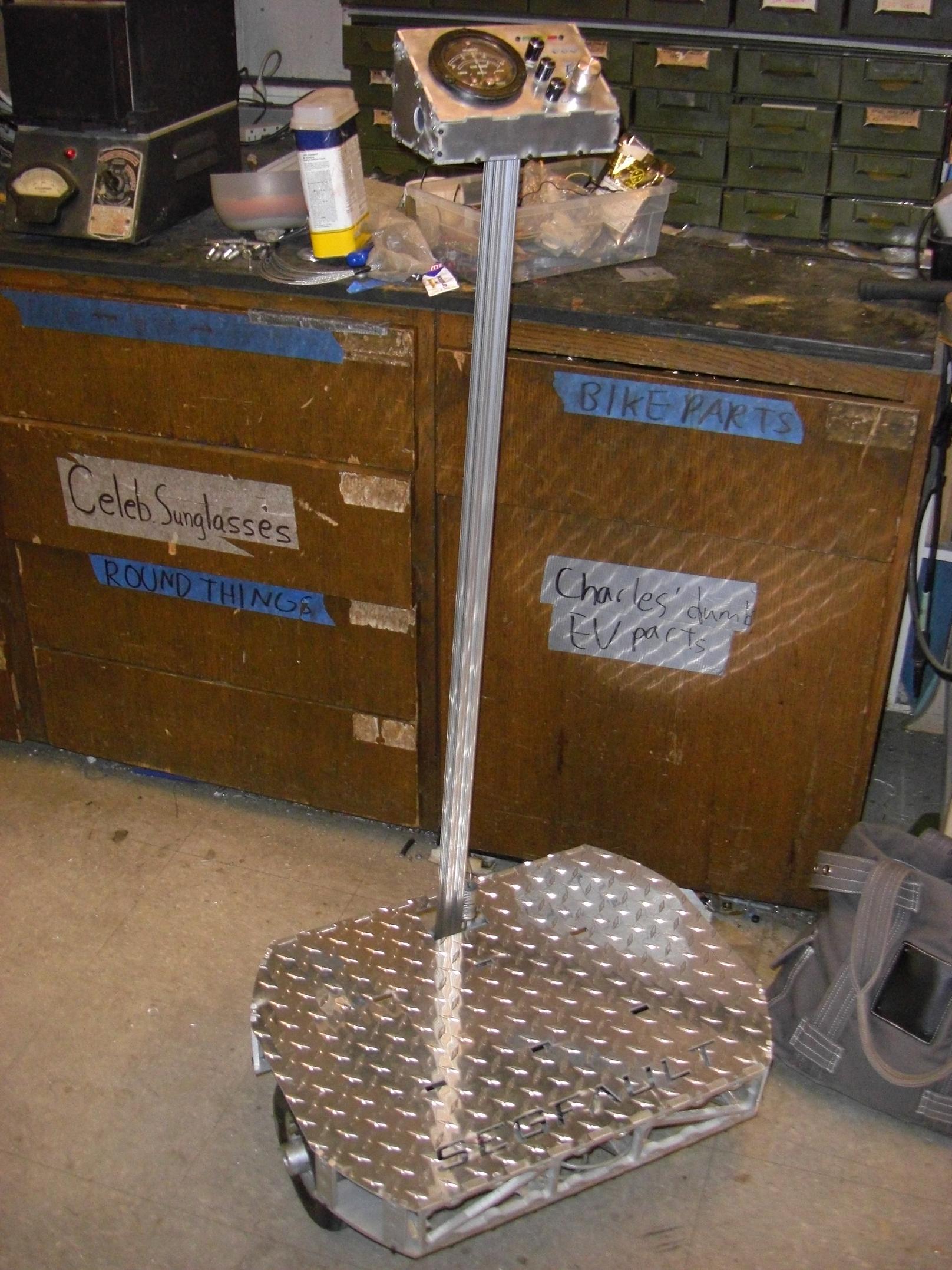
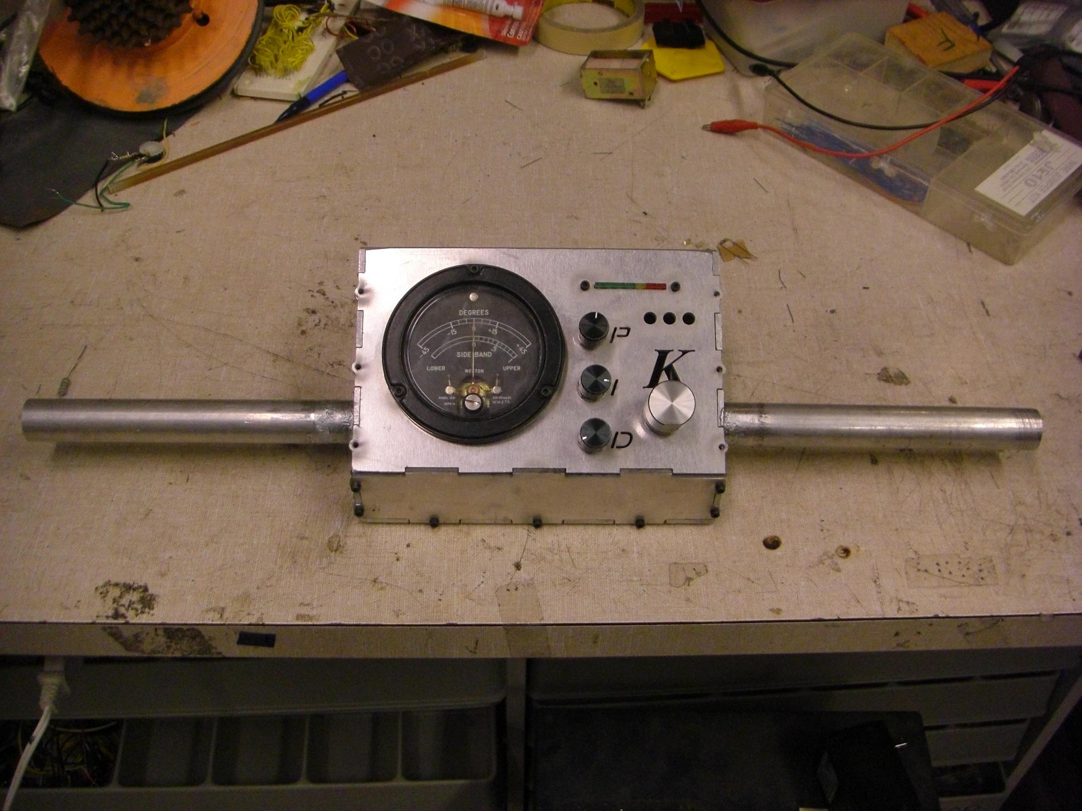
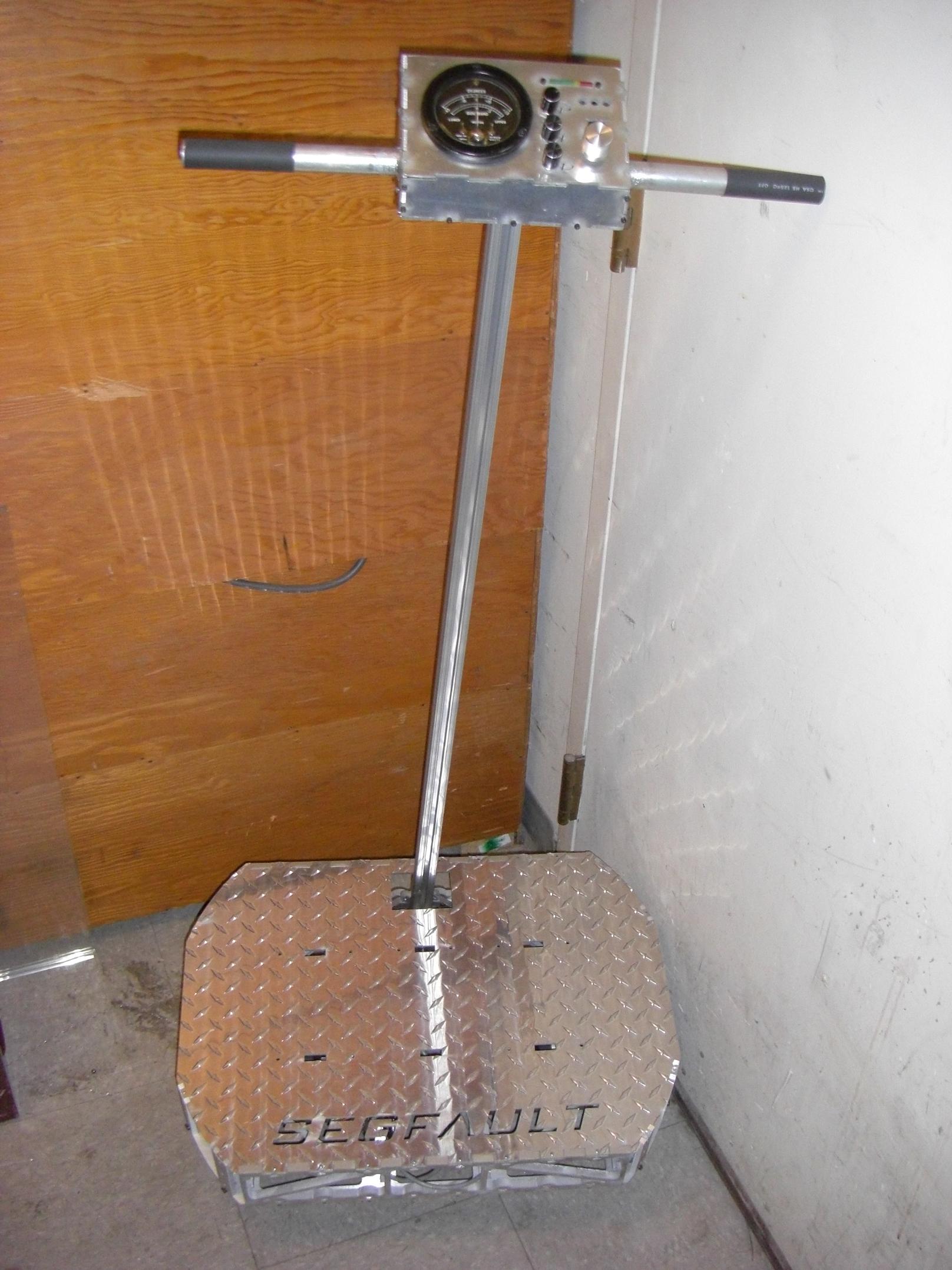
Lots of speculation. Deathblade work probably will not actually begin for a while, because I’m occupied by Cold Arbor and Segfault until mid February!