Pop quiz: When was the last Segfault update?
Answer: It was almost a year ago in January.
As of a few weeks ago, Segfault looked like of like this:

Poor Segfault.
The abridged version of the story is that I stopped reporting on it shortly after the project ran into electrical demons and the gyro-accelerometer filter completely did not function as anticipated. Several more attempts, each getting increasingly desperate, were made during the Spring 2010 term and over the summer. But sadly enough, none were successful in getting it to balance or remain remotely stable, and Segfault has been sitting in a corner at MITERS for the past semester. However, it’s slated to make a comeback…. right freakin’ now…. and hopefully will be somewhat functional this time around.
Let’s start at the beginning.
january
After putting together the final iteration of the balance controller, I started bench testing the locked-antiphase H-bridge drivers.

Yeah. That worked well. I blew out gate driver chips in rapid succession for seeming no reason at all. The FETs were also changed out a bunch of times as they seemingly latched up and shorted. It wasn’t the deadtime/delay circuit at fault – something else was killing the drivers.

I got so desperate that I began putting the FETs themselves in removable sockets. Damn the current processing ability – I was just going to pop them in and out as they died or became questionable, in the interest of problem solving.
When one power-on seemingly killed the entire dead-time circuit, I gave up for the month of January and finished Cold Arbor for Motorama 2010.
I now know that probing the ungrounded high side drivers with a grounded oscilloscope probe was the most likely cause of the latchup and destruction.
april

In April, I signed up to exhibit at the HKN Project Expo. Pursuant to this, I decided to Just Rig Something to see if Segfault would remotely function. I yanked the two Dimension 25A controllers from Cold Arbor and set them to run on 0-5v analog input mode, which was compatible with the signal that the original H-bridges wanted. The Dimension boards didn’t allow any more than 24 volts input (originally slated to be 36v), however, so I pitched some NiCd packs that I had just standing around onto the thing.
The verdict? Yeah right.
The response was extremely poor, even with all the gains set to the highest possible. Segfault would start out balanced, but be unable to stay at that position and entered very high amplitude, low-frequency oscillations (effectively driving forward and backward). As I later found out, this isn’t just due to weak motors or weak motor drivers. Regardless, it wasn’t worth demoing…

So I just brought it as a sculpture.
may
After not looking at Segfault for several more weeks, I decided to take the Victor HV controllers out of Arbor (which by this point was a parts-bot) and try running the whole 36 volts to see if the response would be any stiffer.

Besides switching at only 100 Hz (and making a massive racket using Segfault’s hollow shell as a resonator), the Victors also demanded a digital input signal.
And so I sank yet another level.

Stop judging me.
By this pointed, I just wanted a balancing vehicle, dammit!
This board was thrown together, and some sensor-reading code freelanced, in a few hours.

An IRL screenshot of the Gory Details. The Arduino read in the user gains and steering pot angle and processed them together with the two sensored readings. A complementary filter (a real one, as I later discovered), i.e. my entire two breadboards full of parts (which really isn’t one), is like one line of code.

It was nearing the end of term, and I wanted to just get this thing out of my sight (and mind) for a while. This version of Segfault was the closest it had ever come to working – I think I managed to stay on it for 2 or 3 whole seconds. But to get there, it must have kicked me in the shins at least 10 times. It was also very angry and would occasionally completely lose all control and accelerate wildly into something, or at least until it just fell over.
The falling over part destroyed the handlebar panel and broke several of the precision pots inside. So that was the end of Segfault for a while. Back into the corner it goes…
july
On A Midsummer Night’s Eve, when I was waiting on parts for the RazErBlades, I decided to take another crack at the thing. The Arduino controller was horribly hacked together the first time, and didn’t really incorporate the important part of the vehicle – which was the functioning Degrees gauge.

First order of business, however, was to fix the user interface panel. I found some matching 100K 10-turn potentiometers to replace the broken ones. The wiring was made cleaner by the use of a sacrificed VGA cable instead of a billion different twisted pairs.

I rebuilt the Arduino board with some actual forethought this time around so it incorporated all the pins and inputs I needed.

And here it is, the degrees gauge functional for the first time!
Too bad nothing else was. The test video pretty much says it all.
No matter how the gains were tuned, Segfault was prone to high frequency oscillations this time. It was too twitchy, or perhaps the sensors coupled too much of the motion back into the control loop.
The spark seen in the video was a portion of the battery pack heatshrink wearing through because of the vibrations, briefly contacting the metal frame at two different potentials. It was inconsequential. Unfortunately, the rapid forward-and-reverse gunning of the motors stripped out both of the precision spur gearboxes.
With the forced termination of that test, I decided to just write off Segfault and revisit it yet another day.
now
Mechatronics.
The synergistic combination of Mechanical engineering, Electronic engineering, Computer engineering, Control engineering, and Systems Design engineering[1], and also a really cool class here at MIT, designation 2.737. You should take it if you get the chance.
Basically, my assessment is that it’s everything I should have learned in my undegraduate controls courses (It’s actually a grad-level class, since MIT enjoys watching undegraduates torture themselves by taking G-level classes).
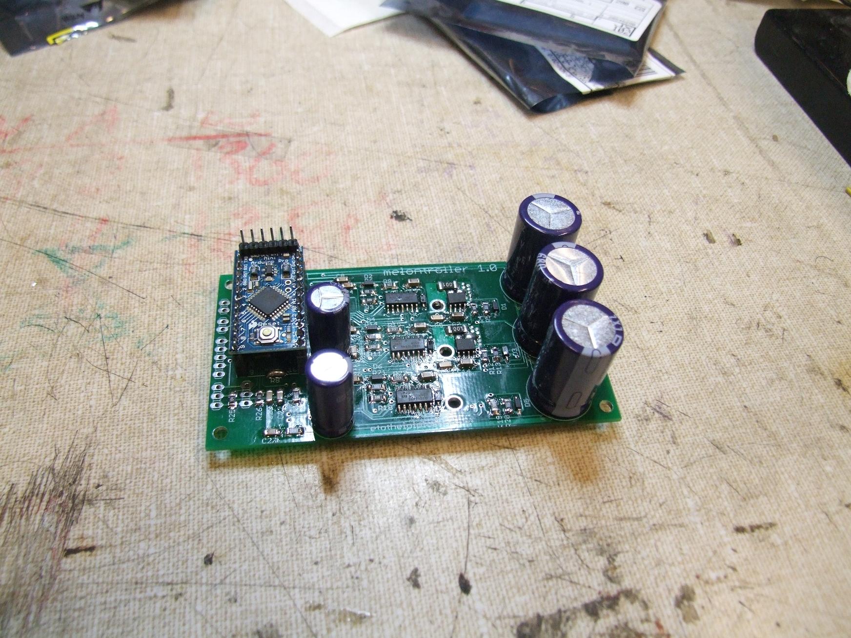
As such, I now know what a real analog complementary filter is. Referencing this paper by K. Byl (nee Lilienkamp), I’ve designed a new balance filter for Segfault, the Adaptive Face-Forward Compensator. I’ve also summoned the 21844 gate drivers and my now full-blown addiction to PCB design to create a new locked-antiphase Segtroller.
The major difference this time? I’m actually finishing SEGFAULT as a part of the grade for this class. This shit just got real™.
Here’s the sneak-peek.

The complementary filter and analog signal processing backend

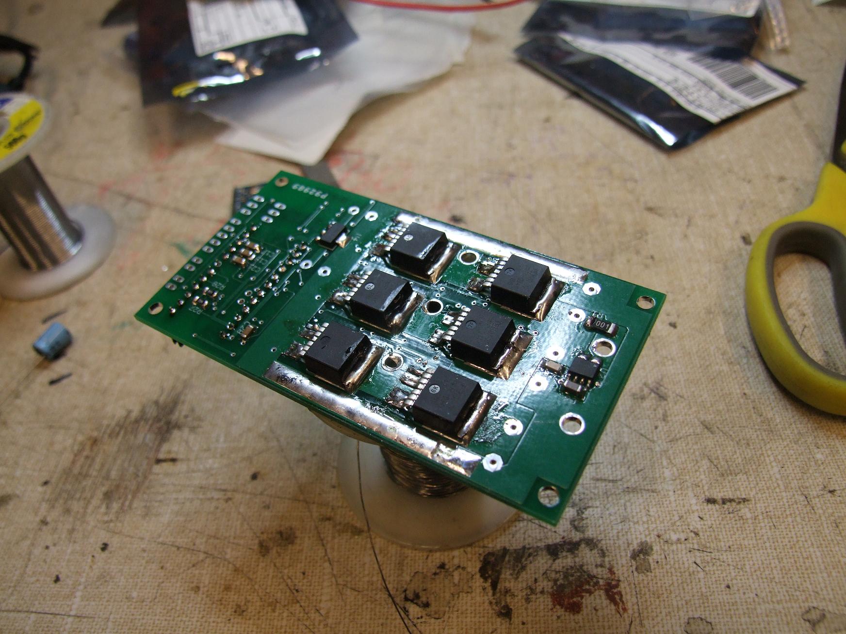
The locked-antiphase H-bridge, each driving a single side
So when’s this due? Wednesday.
By that I mean a few days from now, and between now and then I also have to make sure that 2.009 doesn’t end in utter disaster.
Onwards Adaptive Face-Forward Compensator!