The Overhaul 2 Design & Build Series, Part 4: Ramps, Forks and Clamps, the Pointy Things CADpocalypse

In this part, I’m moving on from the aluminum parts of the bot and putting in some REAL STEEL. First order of business is designing the front armor, the angled pontoons for which Overhaul 1 was somewhat famous for. Next, I’ll put in the lifting forks, and finally the Razer upper clamp arm which is supposed to Razer come down on opponents and mercilessly crush them like Raz… hey, wait a minute.

Welcome to the Overhaul 2 Design & Build series, episode 4: A New Work Plane. Because that’s what’s going on here. So many work planes

The work planes are where sketches are drawn to make the solid pieces. While Inventor will let you sketch directly on the surface of a part in an assembly, I wanted to keep this part a little more separate from the assembly. Therefore, these work planes are defined from the assembly parts, but will still be around if I delete the part (e.g. to replace it with a new version), or edit/delete a frame part.

I honestly didn’t know what I was aiming for when I started. I knew the general shape of things from the sketch model, so I just started making a basic wireframe. The best term I could probably use to describe these first few versions of the pontoons was “Gundam armor”. Impractically faceted and pointy, and likely very hard to make in real life.

Here’s one completed example. I wanted too many things out of one design – the flat sides for easy attachment to the shock mounts, the sloped outsides to deflect KE weapon blows, and the sloped upper panel to protect the liftgear and better act as a w*dge passive-traction-leverage-implement. (It’s no longer polite to say w*dge in BattleBots!)

That’s how many work planes I got up before I decided to just start over. This was the accumulation of 3 revisions, so it included a lot of angles and facets I ended up ditching.

Here we are, after tossing THAT part in the dumpster of bytes. This shape more approximates the original sketch, with its sloped sides and double-angle front. I initially did not pursue this because I was thinking that modeling the non-straight sides would be a pain. To generate the surfaces, I use the wireframe (made of many sketches on different planes) to generate boundary surfaces in Inventor.

The double-angle front armor was borne of some musing about how to overcome horizontal spinning weapons. You can usually do only two things with big KE weapons – absorb them, or deflect them. The former usually ends quite badly.

We saw in the Bite Force vs. Tombstone final how effective usage of material geometry can bounce KE weapons around, since no matter how  much energy you pack in a weapon, your bot still only weighs 250 pounds. The idea of the double-angle pontoons is similar to that of a Jersey barrier, which is designed to bounce wayward cars back towards the correct side of the road. The lower angle slope guides the weapon upwards, and then the sudden higher angle slope destabilizes the now elevated weapon. The height of the angle change is set just barely above the average blade height of all the big hitters at BB season 1*

Adding to this deflective geometry is the soft rubber mounting points, which on a good connect will squash and cause the pontoon to come into contact with the ground. The hope is that this will basically mean the opponent suddenly reacts against the arena floor, adding to the bounce effect.

That’s the theory – we’ll see how it works in practice. But the effectiveness of even a single angle, solidly mounted deflective plow can be seen in the snippets of Captain Shrederator vs. Stinger (trust me, it was even more awesome in person) as well as the Bite Force final.

*The sound you hear is everyone rushing to build variable height weapons

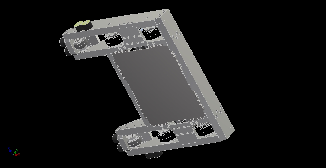
Adding more of “the details” to the pontoons – now they have vertical panels and bottom plates. These are all still surfaces. The plan is to use this part made of surfaces as a reference to “grow” the final plate models from.

For now, I left this surface as-is since at the least I’ve defined the shape of the pontoons and therefore the shape of the front of the robot. I moved onto the next Most Critical Module, which was the lifting arm assembly.

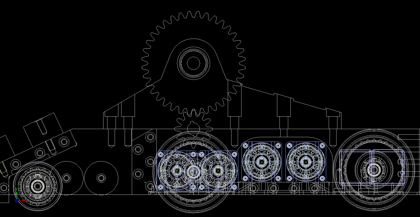
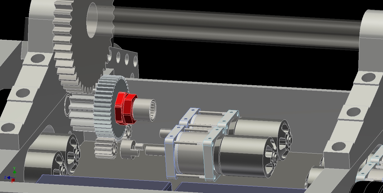
I burped this out after a few hours of thinking about how best to attach the forks. Fundamentally, it’s a big center hub with an ear attached to it where the lift actuator will eventually mount – dimensions and spacings for this were guessed, since I hadn’t designed that yet and wanted to keep it flexible. A similar structure appears on Uberclocker Remix on its main lift shaft.

For OH2, I wanted the forks to be easily removable in the event of oh god I got owned but somehow won. To do this, the fork arms can’t be made a permanent part of something, and the attachment method also needed to be rigid in bending as well as be able to handle what might end up being thousands of ft-lb of torque if I actually use the full crush force on something.

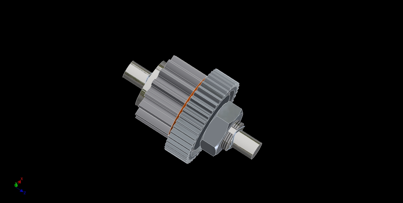
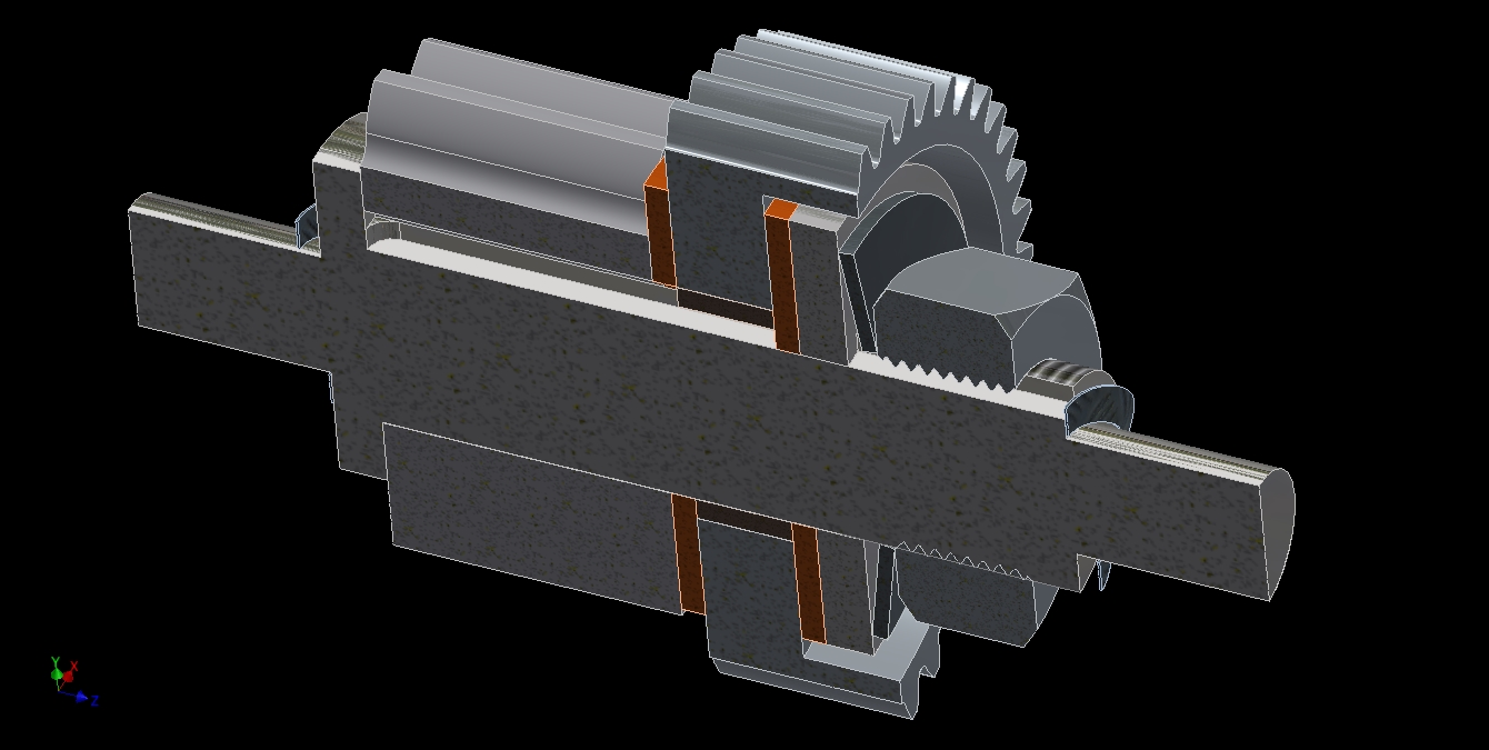
I decided on a dead shaft system where the fork arms also have bearings (rather, just bushings) in them with the hub a separate piece. Eight 3/8″ threaded studs are anchored into the hub, and the forks are retained by 8 nuts once they are slid onto the hub. The way to quickly remove the forks would be to remove the lift shaft (two bolts), then undo 8 nuts per side, and then slide them out.

The lift hub is therefore a totally indepedent structure, so I could conceivably run OH2 even without arms or without the clamp for some reason.


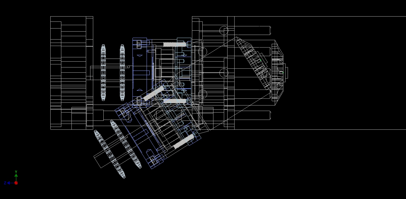
Because this thing will be reacting all of the clamp actuator force through itself, I decided to check in on how the material was going to handle it. Having a 5″ round wad of solid aluminum in the center is great, but not for weight. I wanted to see how far I could hollow it out while retaining rigidity, so it was back to the good ol’ FEA tool.

If you haven’t ever seen FEA before, it basically does all of the stupid bending-twisting-beam calcualtions you had to do in engineering school by hand with a stupid lookup table (IF YOU’RE LUCKY AND HAVE A VERY GENEROUS PROFESSOR), on very finely subdivided elements of the part such that the result is a model of how a very complex geometry reacts to forces and deforms, broken down into simple numerical problems for the computer to crunch through quickly. Quicker than you. No, I’m not bitter about my Mechanical Engineering degree or my classes at all. Why would you even THINK that????

In a typical FEA simulation, you set the constraints (how the part can’t move), set the loads, the materials, and any contact conditions (e.g. between 2 parts, between 2 materials), and let the computer have at it. There’s many ways to do FEA WRONG that I won’t get into detail here.

Here, I’m doing a bending force analysis on the point where the clamp actuator mounts. I wanted to see if this would cause problems with the whole thing deflecting when OH2 mashes down with a few thousand pounds of force. The conclusion is that no, this hub is fine. Double shear for the win!

I usually design to Yield Strength for materials (the point which a material bends). It’s more common to design to Ultimate Tensile Strength – the point when the material breaks. I prefer Yield because if something bends in battle, you’re hosed, but this won’t put any planes in the air…

Having run through the hub once, I started generating the lifting forks. They’re going to be made from some steel tube and some steel plate, cut out into scientific shapes and joined in less than scientific ways by yours truly.

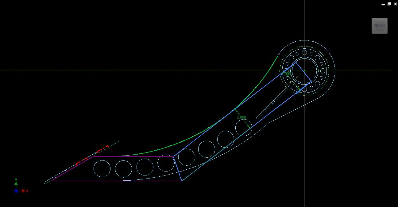
At this point, I was still interested in curved forks. I wasn’t quite sure how I was going to make these yet, but hey, why not try CADing something different? The tube profile was generated with a Sweep of the square tube profile (modeled without fillets).
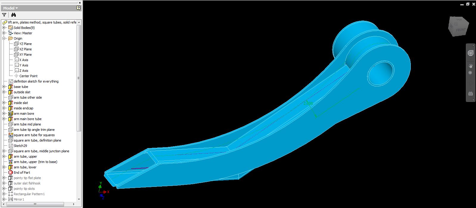
Now in solid form…

I did something slightly nontraditional here, and made each of those elements you see – the tube, the tube caps, the fork curved square tube, etc. a separate solid body in one single Part file. This let me easily reference the parts off each other. To break this down into things I can cut, I highlight and save each solid body individually.

Modeling the “fish hooks” at the end from what will be waterjet-cut steel plates.

Time to see if this fork can stand up to the maximum force exerted by the upper clamp arm. This is a view of the “finite elements” in “finite element analysis” – the computer solves iteratively how each of those little triangular sides deform based on some relatively simple continuum mechanics rules. I modeled for 2500 pounds-force per side, at the tips. This is basically the full, err, bite force of the upper clamp arm (ideally each fork seeing 1/2 of the load).

First attempt: Dorky mild steel tubing.

Nope. Utter failure. Everywhere.

Second attempt: 4130 steel, normalized (not heat treated). This was assuming I could get 4130 in those needed sizes, which later proved to be a problem. This is “edgy” – the yellow on substantial parts of the tube means that on overload conditions like mashing someone into the wall, it could bend and fail there.

Okay, how about using geometry instead of more hardcore alloys? I modeled a single rib that runs the length of the fork arm on the inside. This is not preferable at all, since I don’t want to have something sticking up right where weapons can reach it, but I was interested in how it changes things.

The rib option is workable. This result is a little deceiving, since I had the force concentrated on a small region of the material (the hook), so it will deflect more than everything else. Really what I’m paying attention to is the green-yelow on the rib itself and the tube being largely blue – the rib has transferred most of the stress out to itself, which is what is expected.

The bolt holes are still a little concerning. They are, however in regions which will be tightly bound next to other parts, which simple FEA modeling doesn’t capture.

Instead of the rib, what if I just went to a thicker steel section? Here’s 1/4″ wall tubing (still using 4130 – not even sure if it existed at this point!). The performance is better than the 1/8″ tube version without the rib, but actually not too much. Since the rib is further away from the imaginary axis which this arm would bend along, it can resist the forces far better than more steel closer to the axis. Geometry!

I stuck with this for now, for the purposes of moving on. All of this analysis was really completed in one evening, by the way, so this wasn’t days and days of running simulations. I was willing to trade the inability to use all of the upper clamp force for some “easy” – roll a tube, weld some plates on, whatever.

I’m going to skip ahead a few weeks here, since I like the continuity of this thread about the forks. You’ll get to see the “final” fork design, even if the photos of OH2 from here until a few posts more will be showing this “old” design. Basically, after finishing the bot in whole, I began revisiting parts which I felt I had left “sketchy”, including the forks. In the intervening weeks, I had called around getting quotes and prices for sourcing the arm tube. I had thought I had a handle on sourcing 2″ square 4130 tubing, but I was either imagining it or they changed the Matrix between the design and my revisit.

Bottom line was that I thought using 4130 was no longer realistic in the (Time * Frustration) factor department. Therefore, I decided to capitalize on known available materials, and good geometry.

This time, I’m using a “tube and side plates” approach where the side plates define the shape of the arm and also carry the majority of the weight. The tube really is there for closing off the top and bottom surfaces (sideways rigidity) at this point, and I could even replace it with a rolled curved plate and have an H-profile beam.

This design kind of looks like the original “rib” design, except the ribs are sort of discretized into the new side plates.

The plan was to cut them from the same material as I was making the upper clamp – AR400 plate.

AR is my new favorite  material after building OH1. It’s just so good and versatile, and is my mental go-to if I need a ~140ksi yield strength material that can remain mostly flat. Usually, stuff with that high tensile strength isn’t easily welded, but they designed this alloy specifically for tacking Iron Man suits together in the oilfields with tin cans as filler material or something, so it’s also easily weldable. You do lose some strength in the weld area, but again – geometry can help overcome, or at least offset that.

Throwing it into the FEA module. I modified the location of the force so it wasn’t causing signficant deflection of a single point (the hook) – instead, it’s centered on the large planar face.

Some geometric changes and lightening holes later, and this is the curved arm design. The holes in the side lost about 2 pounds without substantially raising the stress levels.

The geometry here is modeled as “bonded”, meaning no movement at material boundaries is permitted. Clearly this isn’t true in real life – to approximate it, I’d have to weld substantial portions of the holes to the arm tube, or the movement will cause one or the other part to exerience more stress than designed. FEA is one of those things which is tobe melded into everything other aspect of a design, not the end-all answer to a problem.

Skipping forward again another week or two, I was discovering that the tube rolling process was going to be problematic. First, the sides won’t be flat any more – the tube will bow out. Second, there was no tube roller nearby that could handle the material – not in my network, anyhoo. To get the tubes rolled by a known bot-friendly company would have been 2 weeks of leadtime since they were on the west coast.

So I decided to do the final refactor of the design into something which can be built right now with materials and methods on-hand. This means angles.

The “look” of OH2 had been defined by the curved forks, so I wanted to keep an element of them in the final design while hiding the square tubes. Conveniently, the curved side slats are also excellent gussets. The idea was to approximate the curve as best as I could with regular square 2″ tubing.

The above shape with the “elbow” of square tube sticking out underneath…

…which I hid with an “inverse fish hook” coming from the side slats. Hey, they look intentional now!

Looking at the analysis of this part, the problem areas are where I’d expect them – the areas of the side slats near the elbow primarily. (After this picture, I increased the fillet radii substantially and the narrow neck near the elbow was no longer an issue)

As I had modeled these new AR400 plates with anticipated cutting tolerances, there’s gaps in them which I could not force to be “bonded” contact. As a result, you can see the corners of the front angled plate being “highly stressed” – causing the safety factor minimum to be artificially low in that region. In real life, these are going to be welded securely.

Alright, time to undo the timeskip (this was “roughly week of 3/7”). Now we return to the pontoons and upper clamp arm.


I took the surface reference model for the pontoons and literally grew those surfaces into 3/16″ plates…

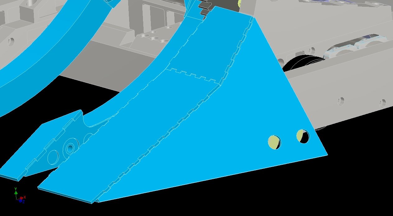
…and then did my usual “edge stiching” finger joint method on the individual plates. This will make the part very easy to self-fixture for welding.

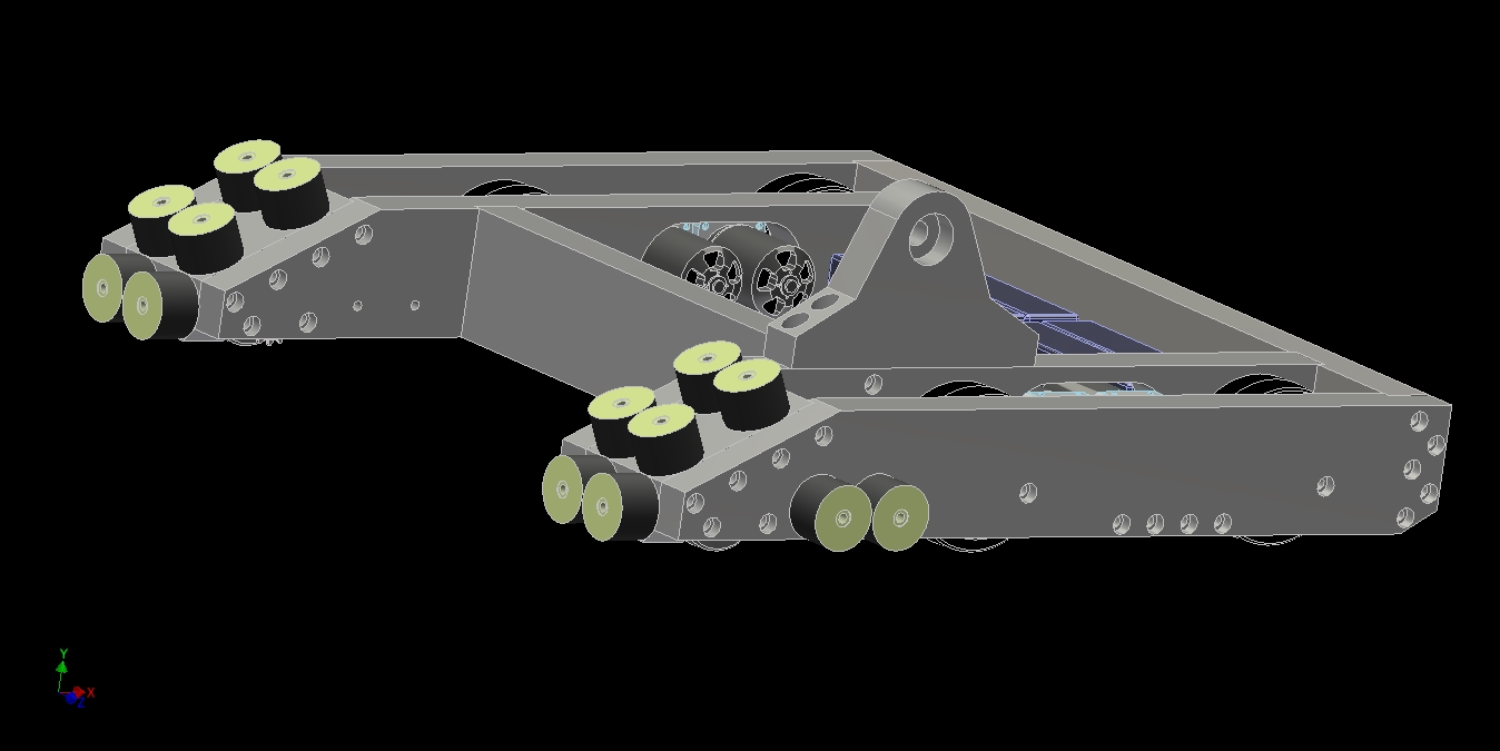
More details, such as internal gussets, have been added to the pontoons, with more to come.

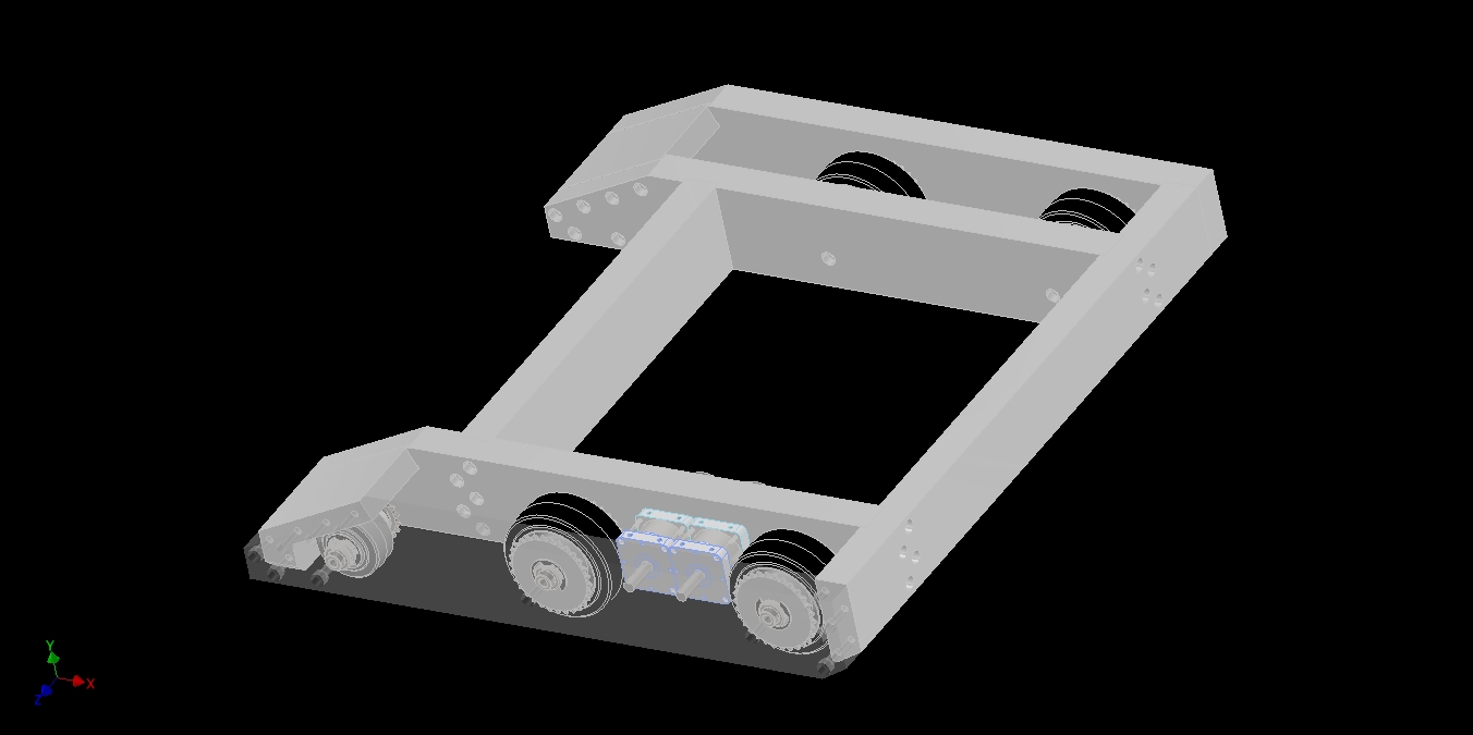
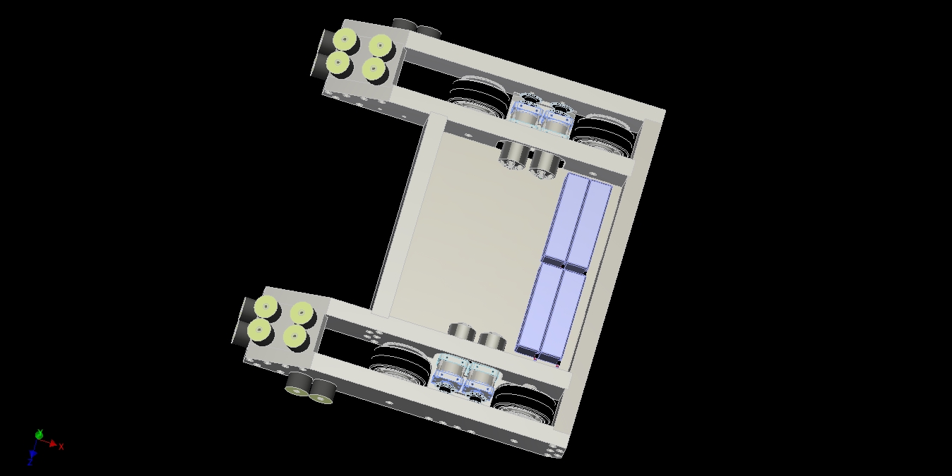
With the front pontoons done, I brought in some more components as a bit of “work-ahead” – thinking about the next step while I’m working on the current one. I knew what I had to do for the upper clamp arm, so I just had to crank it out while thinking about electronics mounting, the bane of mechanically-minded robot builders everywhere. Can I just cast the whole thing in hot glue and be done with it?

Coming up next: The upper clamp arm geometry and actuator!

The Overhaul 2 Design & Build Series, Part 3: The Drivetrain and Lift System CADnado

Alright kids! Buckle in, cuz I’m not stopping the CADvan until I have to pee at some point, usually around Stamford, Connecticut.  Oops, sorry – I forgot that this isn’t me piloting Mikuvan on an average trip to New York Maker Faire or Motorama…

This post begins the long journey from the concept sketch model to what will hopefully be the finished design. The primary goal is to show the evolution of the design and my thought processes.

One thing that will be a little slight in these posts is technical content – the hows and whys of selecting a certain component. I already knew much of what I wanted to work with when I began, having built Sadbot as a power system mule before this all started.

What I’ll do is recap the construction of Sadbot and how many of the power system components were picked after this segment of CAD model posts – there is a lot of interesting science to help advance the state of the sport which I was able to distill. What “engineering” content there will be in this series of posts will be more centered on mechanical engineering and materials, since this IS designing the frame and structure.

We begin with the trailer photo in the previous post, the new OH2 frame besides Sadbot:


Using the information about component placement from the 3D sketch model, I began making individual part files that represented the frame rails. I tend to start with drivetrains and bases first. Not everyone does it this way, but I figure if the robot can’t move, then I’m in bigger trouble.

The choice of frame rail material is massive 1.5″ by 4″ aluminum bar stock. I went for this extraordinarily beefy material since OH2’s frame was, for the most part, also going to double as its armor. The aluminum rails will be hollowed and machined out (“hogged”) where needed to save weight. One upside of using a large starting section area is that even if much of the material is removed, it is still more rigid than a full smaller section.

Great, first I’m a Bite Force knockoff, now I’m an Icewave knockoff.

The thick rails allow the use of offset bolt patterns to increase the fastening rigidity of the joint (compared to, say, 5 bolts in a line) as well as avoiding the postage-stamp effect where the bolt holes become a neatly placed line of perforations.  But now it looks like an Icewave knockoff.

All of the frame bolts are 3/8″-16 size.

Modeling in more of the structure, including the cross-rails. The initial spacing of the wheels was determined by the sketch model, which had wheels positioned according to the drive motors. This, as you’ll see, will change a lot.

One of the first things I modeled “for real” was the drive wheel hubs. This uses a retaining ring system similar to Überclocker’s final wheel hub interation, and is designed for the 2″ wide Colson series – 5″ x 2″ in the back, 3″ x 1.5″ (with a spacer) up front.

The hub permits sprockets to be mounted on one or both sides, and the center bearing is a needle roller bearing system to minimize friction. To transmit wheel torque, the whole hub is double-keyed with 0.25″ standard keyways.

Modeling in the plate that holds the drive motors now…

One of the issues which plagued OH1 – and really, most of my bots – is serviceability. While we became fast at replacing something on OH1, that doesn’t mean it was good. I aimed to make all top-level components which could break – motors, batteries, controllers in particular – be serviceable without taking apart the frame rails. The wheels would be an exception, as the shafts make up part of the frame.

In particular, since the motors and controllers were going to be highly experimental, I wanted the ability to swap them out quickly. OH2 has four drive motors not just for power, but in part for redundancy.

Shown above is the drive motor area, where I’ve designed them to pop out the bottom. After unbolting the motor mounting plate and disengaging the drive chains, both drive motors on one side just slide out from underneath. There will be a small gap in the baseplate for the rotation space, which will just get covered with some duct tape to discourage the collection of arena grunge.

More motor mounting details get modeled in on the underside. The motor mounting plate is roughly T-shaped.

I originally had the four holes on the outside also facing out the bottom, but it would have required that region of the outer frame rail be made pre-emptively solid to accept the threaded holes for the bolts. To keep the design more flexible for now, I decided to keep the holes in the more space-saving configuration by having the bolts point into the smaller motor mounting plate.

I flipped the design back over and added all the rubber shock mounts to the top. I bought a few different candidates from McMaster-Carr prior to this, in order to appraise the candidates.

The strategy with the shock mounts (or as we kept calling them, wubbies) this time is to use many more smaller ones in a more distributed fashion. Not only will there be these facing upwards and forwards, but also some facing sideways.

When the bot loads the front pontoons this time, the six shock mounts on each side will be put into compression and tension to react the load, instead of just being bent. Twelve ought to be enough to hold the forces – if not, McMaster has harder versions of the same mounts.

I’ve generated the motor mounting plates here and have put in mounting features for the gearboxes. The holes are slotted for chain tensioning adjustment.

The vaguely completed frame so far! Here, I’ve added two of the side shock mounts. These don’t play as much of a role in a lift, but if I get whacked on the side, they help isolate the pontoons from the frame.

With all of the frame rails and critical features in place, I added a baseplate. The school of thought for fastener placement here is “Whatever patterened the easiest”. It’s likely not all of these fastener holes for #10-32 countersunk-head screws will get used.

Now that a box frame with bottom was complete, I started bringing in other parts for sizing verification.

With the shape of the frame basically defined, it was time to start putting up the arm towers.

In keeping with my preference for the “This is a drivetrain. Everything else bolts on here.” design school, I decided to make the arm towers a separate piece each. Here’s pass #1 at the design.

This was also a move for manufacturability. The idea is to make everything from the 1.5″ x 4″ barstock, and then waterjet-cut the arm tower to rough shape, then finish-machine.

Pass #1 got the idea across. I decided to use the arm towers to additionally brace the large cutout in the side rails where the motor pass through, so I extended them past the motors. Furthermore, the long rear slope evokes the arm towers of OH1 more (it had a highly sloped backside).

The arm towers are anchored with five giant 1/2″-13 bolts apiece. Nothing will fail here… if the arm towers get torn out, something very, very bad has already happened and stripped threads are no longer something I need to worry about.

Once the shape of the lift towers was set (for now, anyway), it was time to fill in the details.

HUMONGOUS SPUR GEAR!!!

From Sadbot experimentation and some math, I had a range of gear ratios which would be acceptable for the lifting forks. The goal was to get an arrangement of some combo of gears and sprockets to get into tha range.  The ratio to hit was approximately 180:1, with 16:1 of that taken care of by the P80 gearbox on each motor. This would permit the Sk3 6374/149 motors to lift a 250lb opponent at the very end of the roughly 24″ long arm at roughly 42″ per second.

Almost 4 feet per second, up or preferrably also down. Überclocker was well known for smashing opponents on the arena floor over and over, and this was a move I wanted to duplicate with OH2. That’s literally 10 times the speed of OH1’s linear actuator lifting arm.

Why gears? Remember that in the initial sketches I had a big sprocket modeled. Well, after thinking aout it during the arm tower designs, if I was going to have unboltable arm towers, then what good is it if I have to find and remove a chain master link to service the liftgear? A HUMONGOUS SPUR GEAR will permit me to unbolt the arm towers and just lift everything off for independent service, and furthermore, just smash it on and tightened the bolts down when done.

The liftgear must be then beefy enough not only to stand the static force of holding an opponent – already 500+ft-lb of torque at the lift shaft, but also the forces of me slamming the transmitter stick in the opposite direction of travel and the impacts with the floor. For now though, ratio was more important than tooth size.

The idea was to have the big gear be part of the removably top assembly. So to start off, the little gear (“pinion”) must be mounted in the frame. This first attempt was with a 3:1 output stage, which kept the intermediate stage requirements also reasonable – it’s difficult to get more than 4 or 5:1 in a single stage without making one gear tiny.

The gears shown are 6 Diametrical Pitch, 36 tooth and 12 tooth.

But that design left the pinion directly in the line between the frame and lift towers. Attempt #2 is a 4:1 output stage with a 48 tooth 6 DP gear and a 12 tooth pinion.

For those keeping track, a 48 tooth 6DP pinion is 8.3″ across. It’s the size of your face.

While the 48/12 arrangement put the pinion at a good location on the vertical axis, gear calculations showed that the tooth forces were going to be too great. The smaller the gear, the more tooth force is needed to transmit torque. I was going to have to make the gear from hardened tool steel for it to have a chance. Therefore, I downgraded the output stage to 3:1 and decided to use a 15 tooth pinion (Alright, so it’s 3.2:1. Bite me.)

To retain the ratio, the lift towers had to be increased in height slightly, which was something I was willing to accept.

By the way, these gear tooth numbers aren’t being magically summoned. I was thumbing through various gear manufacturer’s catalogs and industrial suppliers which carried those products in stock. I wasn’t going to start specifying custom-machined gears just now…

One of the difficult “real life engineering” things I tried to teach in the 2.00gokart course for the freshmen and sophomore students was that you had to be able to buy or source the thing you designed, so don’t spend too much time optimizing for the peeeeeeerrrrrrrrrfect system. Chances are, the supplier won’t have it, and your beautiful numbers will crumble to dust in front of you like a timeless story of fairy tale justice.

Since both 48 and 15 tooth gears existed in real life, I settled on that for the time being. Now it’s time to design the intermediate stage. The input ratio – 16:1 – and the out ratio – 3.2:1  – were both anchored. To hit the target ratio, I needed a 3.75:1 intermediate ratio.

I had to play some geometry games. Shown above are the two lift motors, each with a 12 tooth pinion – the smallest available pinion in that Diametrical Pitch with a 1/2″ keyed bore. And really, the smallest gear I was comfortable fitting on the motor shaft due to the bore size. Any smaller and the distance between the keyway in the gear and the bottom of the tooth become very small, risking it failing there.

With a 12 tooth pinion, to get a 3.75:1 ratio I would have needed a 45-tooth gear. Unfortunately, I couldn’t quite find a geometric solution here. The diameter I would have needed to fit the 45 tooth gear meant pushing the lift motors further apart and further down. The baseplate is one constraint, but the shaft axes impinging on the drive motor area was another one. Plus, nobody seemed to have 45-tooth gears in stock. It’s a bit of a weird tooth count.

A 42 tooth gear made for a near-perfect arrangement where the motor were seated on the baseplate and also spaced closely together. This meant I could only get 3.5:1 in the space, leading to a total ratio of 179.2:1 from the motor.

Okay, whatever. That’s 180 enough. 2 plus 2 equals 5 for large values of 2, and sufficiently small deviations about a designed optimal point will generally go unnoticed for the majority of loads. I was honestly happy I could get close to 180 at all. The best part? Everything was in stock!

I moved forward with the 42-tooth intermediate gear. At this point, I also began to think about how to clutch the output shaft. Having such a high gear ratio makes your system prone to inertial damage. The very act of suddenly stopping – like slamming an opponent on the ground – causes the motor’s inertia to be magnified many times through the gear ratio, adding more stress to the gear teeth in a very short amount of time.

Plan A of clutch design was using a Trantorque keyless bushing. These things are cool. When you stuff it into the bore of your gear or sprocket and tighten the nut, the outside collar expands and inside collar contracts, causing immense friction. That’s how it transmits torque. Transmits. Torque. TranTorque. Hey, I think I get product marketing, guys!

My plan was to purposefully half-assedly tighten it onto a hardened and polished shaft such that it could slip at some hopefully pre-determined load. Hardened and polished is critical so the surface does not gall up and destroy itself – both the smoothness and hardness are important.

How do you size gears? Well, you could pick up a mechanical engineering textbook and do it OLD SCHOOL COOL, or use the gear generators and analyzers now built into many modern CAD packages. These are the equations and tables in those textbooks packaged in a way a lazy millenial* can understand.

That’s how I found out the 12 tooth pinion was going to be very unhappy. The key number for my purposes is the Sf value to the right. That’s the Tooth Breakage Safety Factor. That’s what you DON’T WANT TO HAPPEN. For the 12 tooth pinion, it was getting awfully close to 1 – and by that I mean like, 2 or 3. In robot-smashing duty, you never, ever design anything for a low safety factor. I’m sorry, aerospace & rocket folks. Your robots always lose for this reason.

Gear 2 is the larger gear, and notice how its safety factor is something like 7.6. This tells me the gear material is very much overkill for strength. In fact, it might be fine being made from aluminum. I decided to keep modeling it as steel for now for weight purposes. When I need it, I’ll hopefully be able to shed a few pounds by moving to aluminum – this would entail, for example, waterjetting an epic gear from 7075 plate or similar.

The other very red and concerning looking numbers are not of interest to me here. One is the Tooth Pitting safety factor, and the other is the Static Contact safety factor. These are important if your gears are running for a long time and you’re looking for longer term tooth wear reliability. All modern gear design methods factor in many different little environmental conditions as well as the desired running lifetime.

For me, that’s like, 5 minutes – so I really only care about teeth breaking.

*Note: I am probably on the very trailing edge of who’s usually considered millenials these days, being a product of the late 1980s like my van. I use the term both to express indignant outrage and to disparage my peers’ achievements depending on what is politically advantageous at the moment.

Using the Trantorque GT clutch-bushing idea, I continued to build up the infrastructure of the liftgear. Here, I’m putting in downloadable models of bearings and shaft couplings to see how much space I have.

One design evolution was in the length of the bot at this point. I wanted the liftgear to be double-supported, meaning they were surrounded by frame rails on both sides. This enhances the rigidity of the area immensely, since the gear loads were no longer being supported by twisting the front frame rail.

But already, there was no space to put a secondary frame rail here. The lift motors and drive motors were too close together.

Solution: Make the bot an inch longer. The 3 vertical holes are for a 0.75″ thick transverse frame rail to help bolster the motors.

As seen here!

Alright, a few days after this design session, I received a Trantorque GT bushing I had ordered in the mail. Conclusion: no

Not because the idea was flawed, but that the bushing is made from a soft steel. After all, it’s supposed to be mushed into the bore of a large fan pulley or something and stay there for decades. I became concerned about controlling what slips on what using this bushing. Bushing slips on hardened, polished shaft? Sure. Bushing slips against bore of unhardened, similar-alloy steel gear? Bad. I’d be machining the bushing out after that.

So I threw that idea on the ground and decided to make my own. Shown above is a very drastic torque limiting clutch.

Here is a cross section of the clutch. I just took an industrial torque-limiting hub for sprockets and made it longer.

Those things are really simple. A big nut pushes a (usually) Belville Spring onto a pressure plate which is keyed into the shaft, and the pressure plate is what transmits the torque. The brown material is clutch pad, which McMaster-Carr sells in VERY EXPENSIVE sheets.  Some quick calcs show that this clutch should be able to hold up to around 500 ft-lb of torque with that big Belville spring I picked out from McMaster-Carr (which sells it in VERY EXPENSIVE packs of………… 1). There might be a pattern forming here, I think.

Dropping the new torque limiter in the CAD and continuing to build up infrastructure by air-placing parts.

A set of spider couplings join the gearbox output shafts to the intermediate gear stage.

This is here for 2 reasons. First, for springy compliance: While the big torque clutch gives frictional compliance, a single high-energy impact, such as getting tapped by the Pulverizers or an opponent bot’s hammer or being run into a wall with the arm up, etc. could still put enough energy past the intermediate gear stage before the clutch even starts slipping to damage the gearboxes. The springy compliance absorbs this brief input of kinetic energy by deforming the rubber/urethane core of the spider coupling.

So the liftgear has two protection mechanisms. The torque clutch prevents the motors from driving and overloading the mechanism, while it and the spider couplings work together to prevent external driving forces from being shoved back into the motor with a vengeance.

Once I was happy with the air-placement of everything, I began wrapping frame rails around them.

Here, reason #2 of the spider coupling’s role is revealed. I’m also using them a bit as dog clutches in conjunction with a motor mounting block that can be unbolted and slide out quickly should something bad happen to the lift motors and they need to be replaced. Another design for serviceability factor!

This basically concludes all the design work on the liftgear. From here, after letting the design bake for a little while, it’s time to move onto designing the front armor pontoons.

We begin with a bunch of reference planes…