Candy Paint and Gold Teeth Might Be A Thing After All

And now, back to your regularly scheduled content!

I determined that the next location to practice my back-alley bodywork skills on Mikuvan was Oops! I mean, we interrupt this weekly installment of Big Chuck’s Automotive Blog to bring you ROBOTS!

It’s been a while since the last Candy Paint post, and tons of work have been finished, but there is still a majority to go. I’ve finished most of the small parts and machined assemblies that will go on the bot, but the frame is not yet welded. I hired out the frame welding to my associate Jack at the D-Lab space down the hallway; since I determined that trying to learn aluminum welding and make a critical weld at the same time is best avoided, especially if I don’t get to arbitrarily remake the parts if I mess them up. The flip side is that I may only have the frame in hand by this coming weekend

Which is one week from Motorama. Uh oh.

In the mean time, let’s start with some machining. Rather, the product of someone else’s machining (boy are we off to a good start):

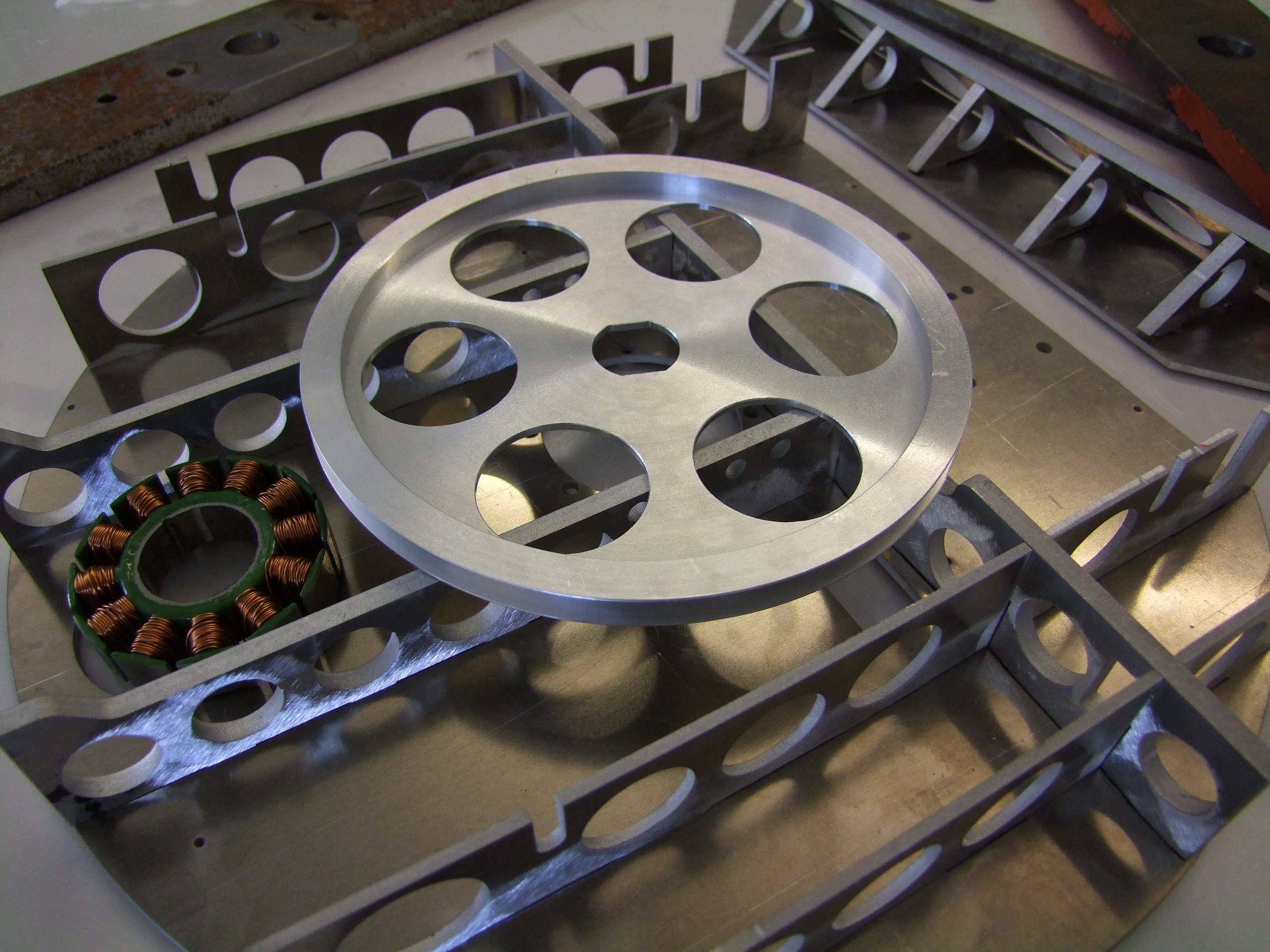
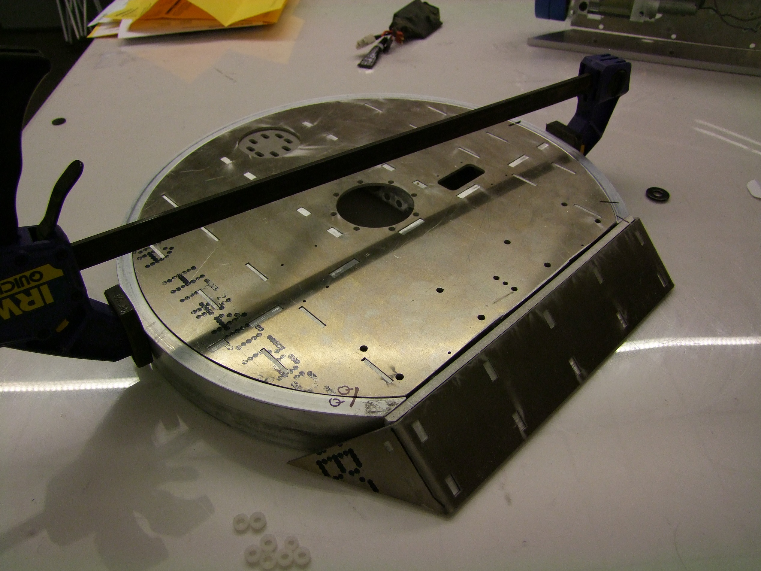
This is the main blade pulley for Candy Paint, sourced from a shady Chinese shop via mfg.com.

Alright, it’s not fair for me to call them ALL shady, since if you can machine a part to a customer’s specified requirements and tolerances, then there’s no arguing really. Here’s some hard data for the curious. I ordered this part in quantity 4 to sweeten up the deal very slightly over a one-off. The cost was $25 per part, single piece machined 6061-T6 aluminum. There was an engineering fee/setup fee of $40 and the shipping came out to $80 because I had asked for an express air service since I needed them quickly.

All up, about $220 for FOUR of these jobbies. These are hard numbers for your amusement, if you choose to have robots machined by proxy. As far as I can tell, the aluminum is legit.  With any dealings with Chinese job shops, always make clear what you need/want and in what timeframe – for instance, I asked the shop explicitly whether or not they could ship before the Chinese lunar new year holidays, which is like right now. Well, they sure as hell did! Last year, I asked the same for the DeWut hardware; that one literally got out the door the day before closing.

The total turnaround time was 3 weeks. One week for the quote to slow-cook on MFG, and two for production and shipment (so really, prod took only a few days from payment because of shipping).

Okay! So, now that the Chinese have beat me to my own game, I’m going to start machining things.

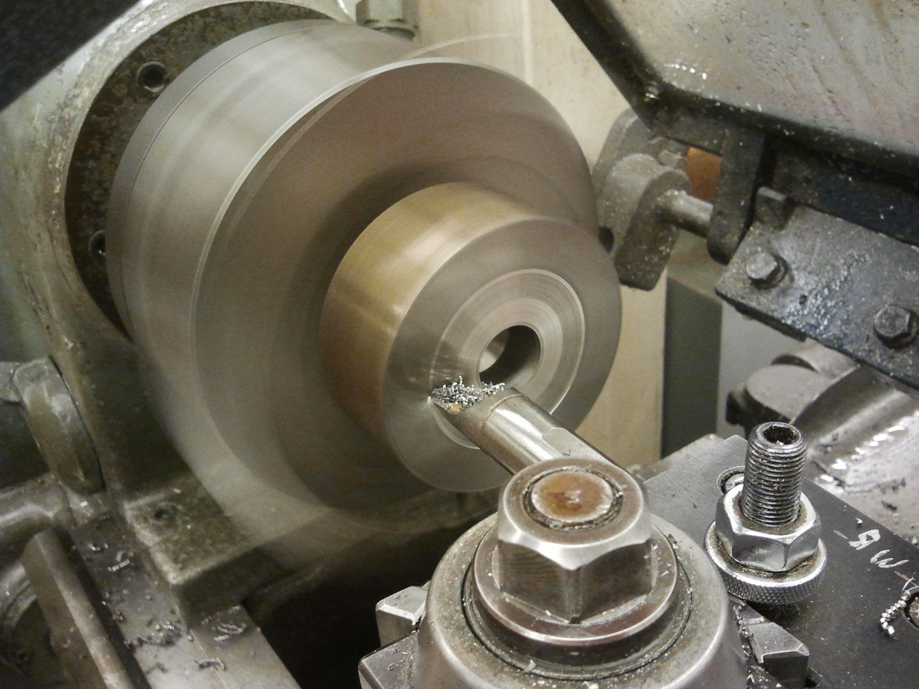
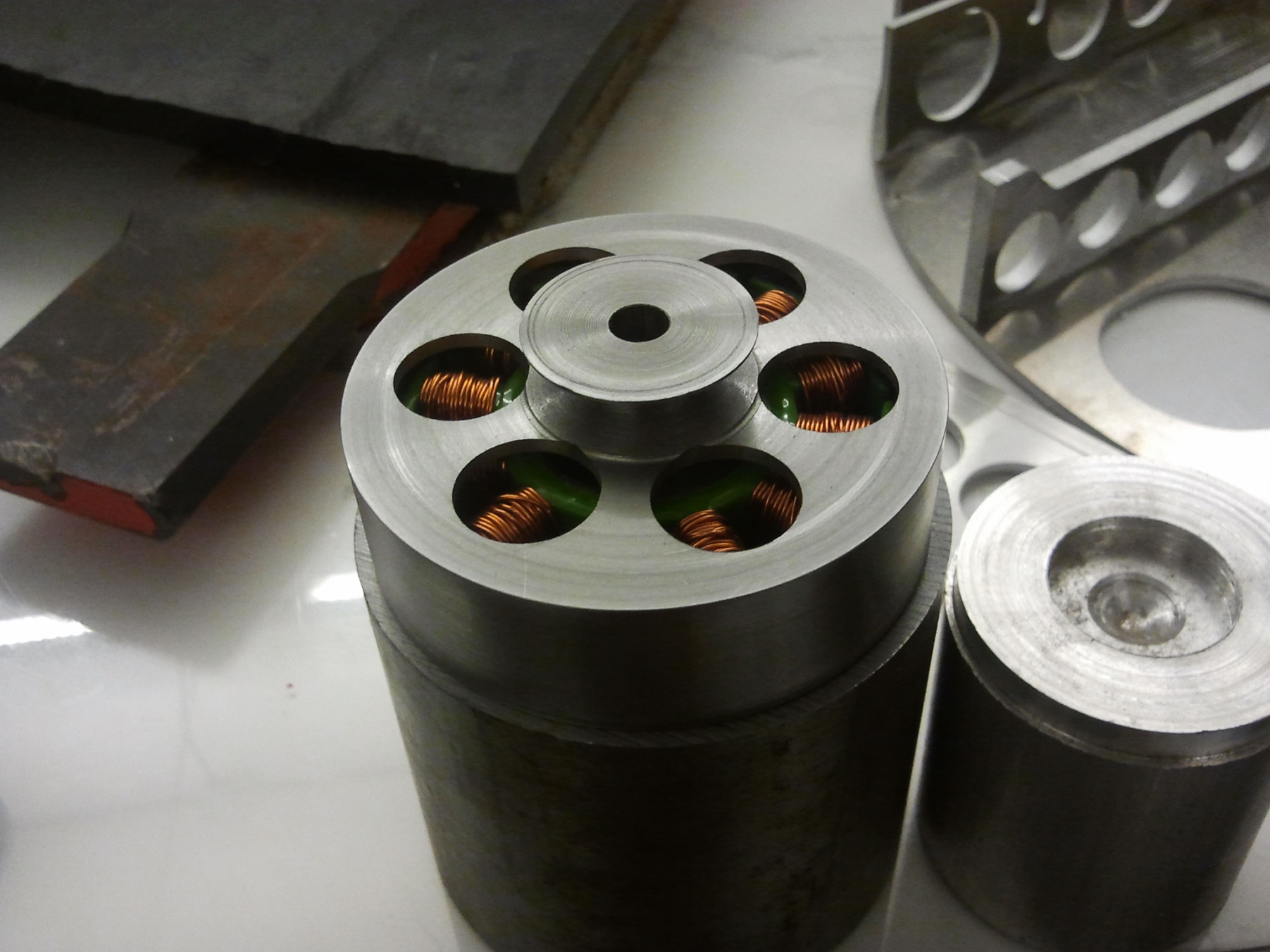
Okay, fine, I’ll get up early to use a nice machine in a nice shop. Here’s the main weapon motor can being carved from a SOLID BILLET OF STEEL. I knew this was going to be tricky going in because of the extremely space-constrained nature of this motor, so one piecing it was preferable over a press fit anything. This is the rotor portion being made, where the magnets will eventually sit.

It took me a while to get used to 1. machining and 2. on something big again. I had forgotten that carbide loves going fast, and it took a tap on the shoulder and a “Dude, you should be running like 500 RPM on that at least” to kick me back in gear.

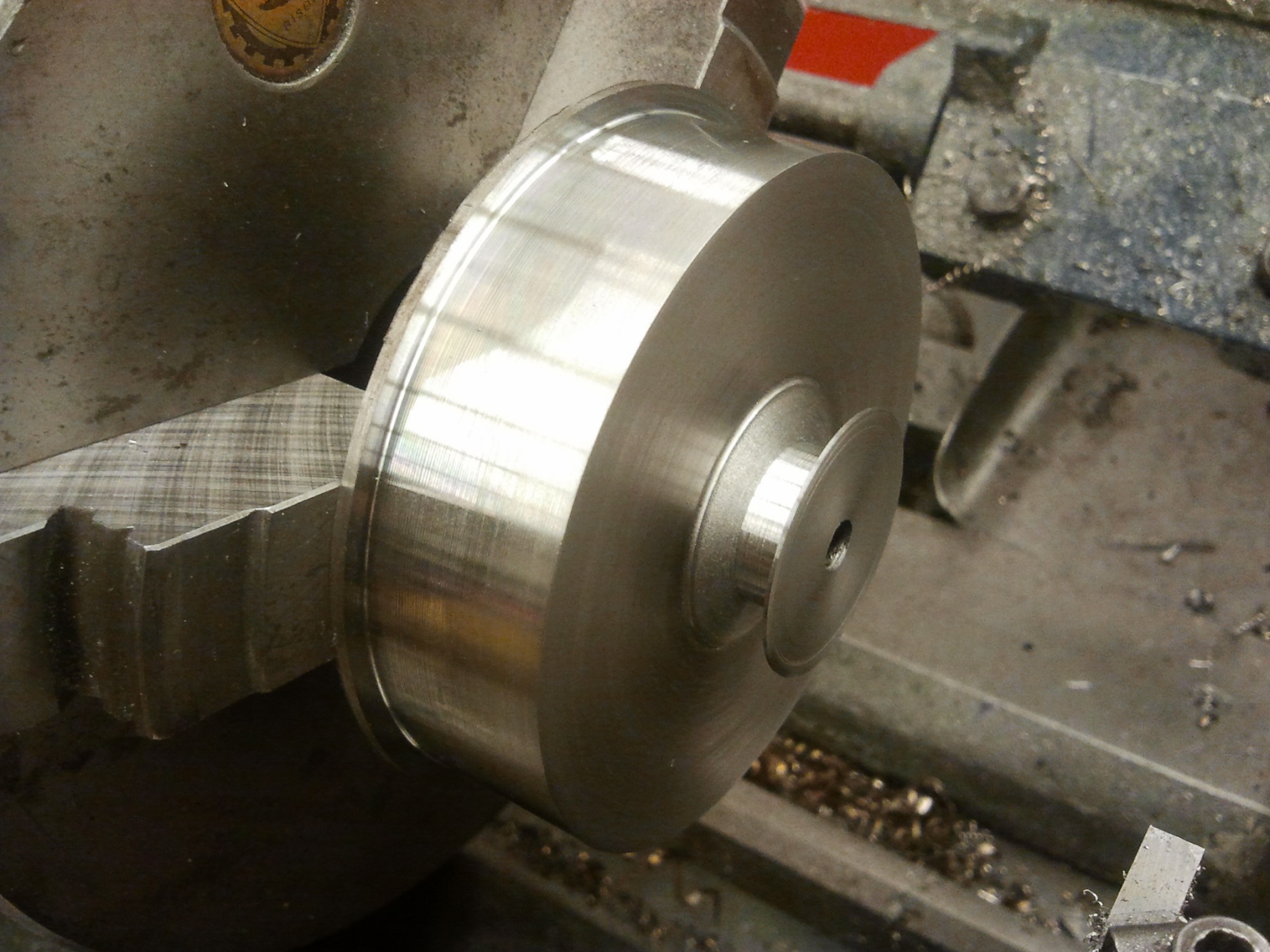
Much better. Now for the pulley side.

For the close-in pulley groove, I used a straight grooving tool in a cutoff bar holder (for left side clearance), but with the compound slide set to the V-groove half angle, and just fed very gently.

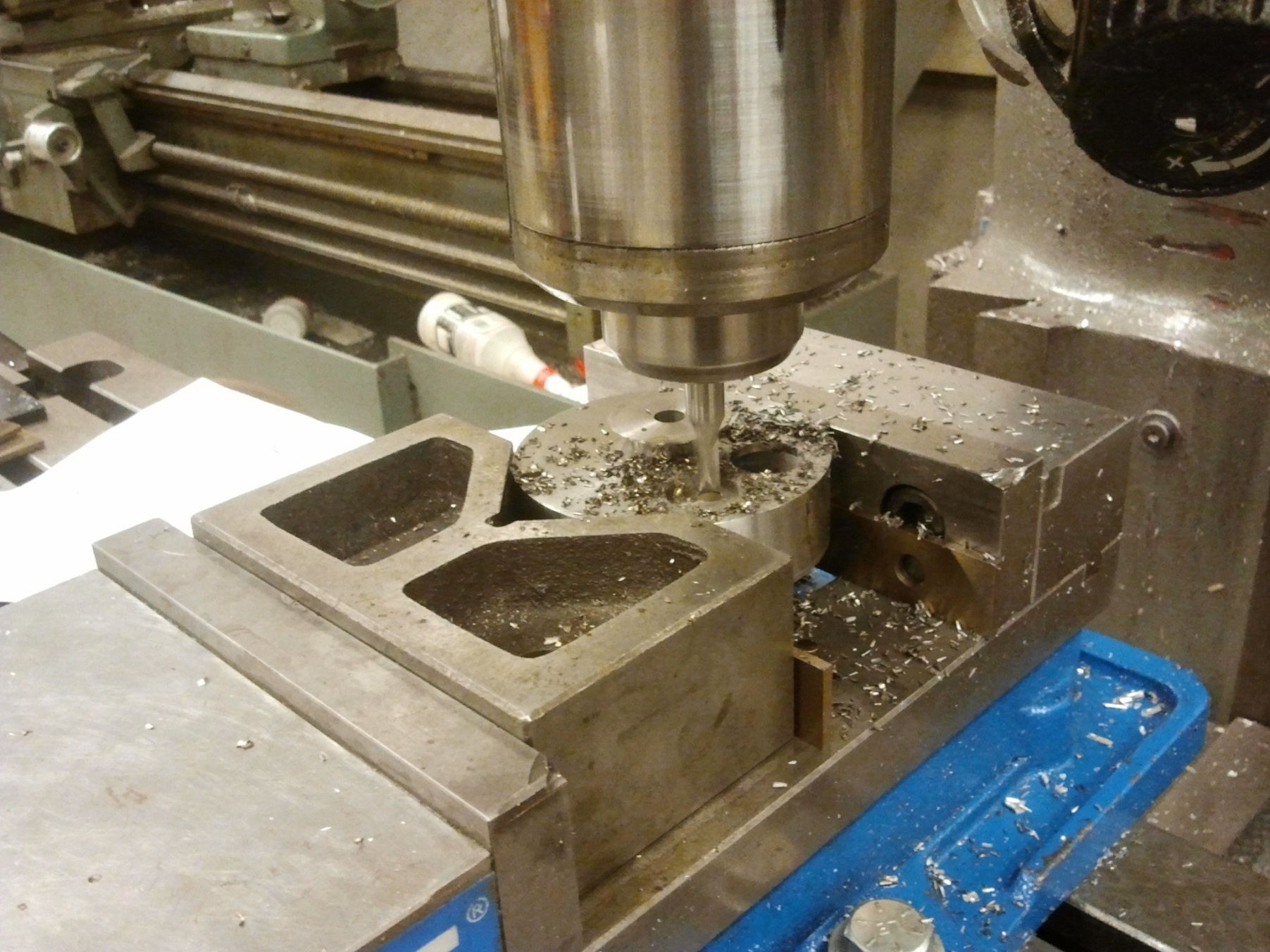
After cleanup of the ‘skirt’ of the rotor, which was unreachable in the first setup, I pitched the thing on an EZ-Trak style 3-axis CNC machine (the things based off Bridgeport mills) and conversationally bored the six rotor holes – conversationally as in WHY IN THE NAME OF BABY ROBOT JESUS HAVE I FORGOTTEN HOW TO USE THESE DAMN THINGS.

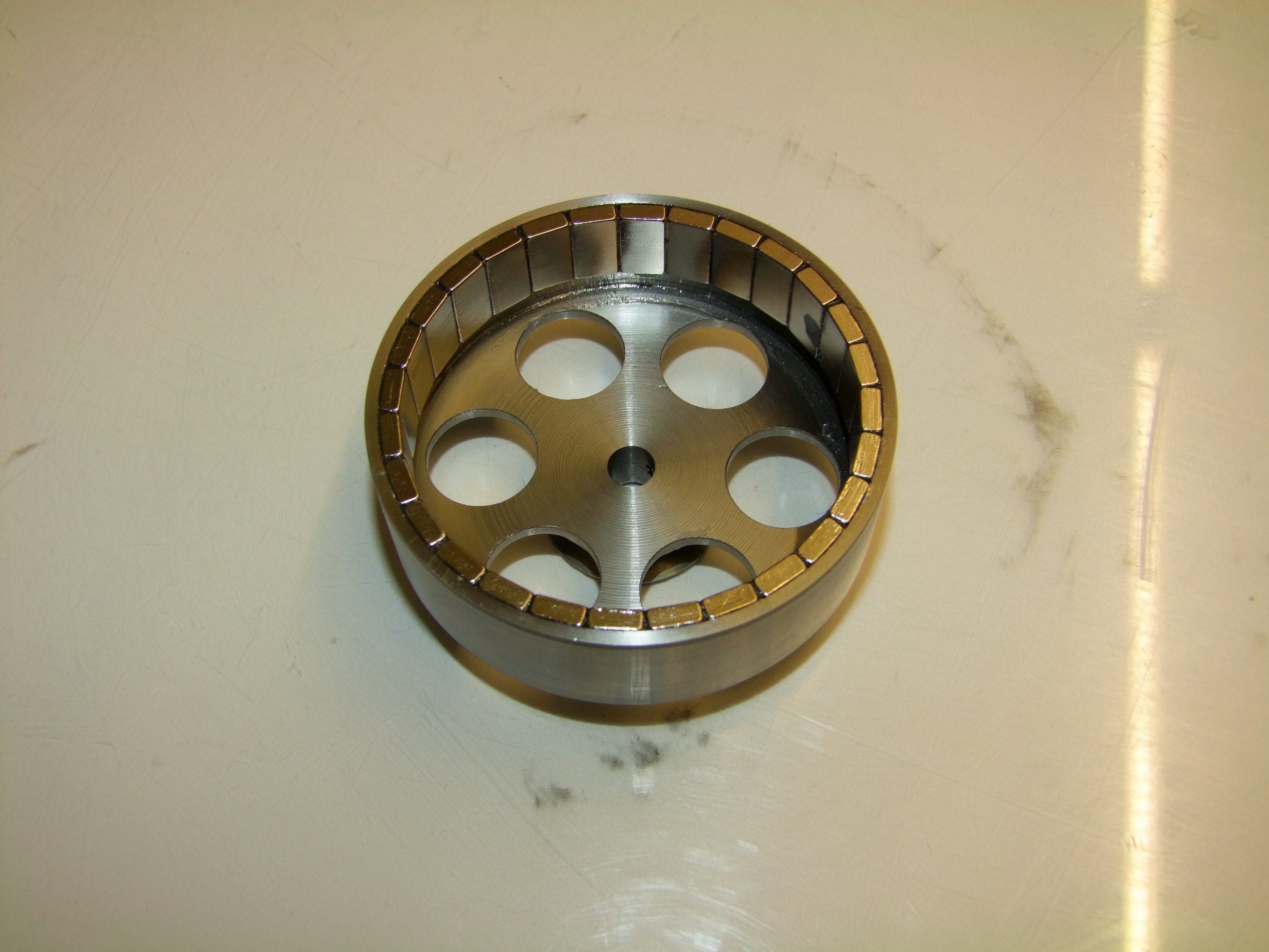
The completed rotor, sitting on top of the billet of steel from whence it was cast.

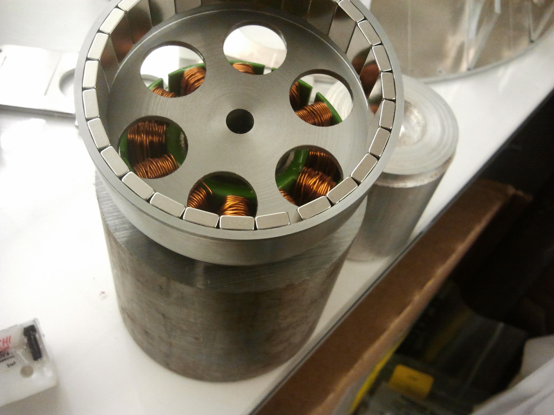
Time to line up the magnets and…. well, shit.

I typically don’t make full-circle magnet rotors unless I had already tried making one and know that the magnets fit. This little 2mm gap in the magnets is entirely made of manufacturing tolerance. The magnets have larger fillets than I expected, so they packed just a little bit closer together. For instance, if I were to make another of these with the same pile of magnets, I would know how much diameter to reduce by to get a clean fit.

Not a disaster, since all this entails is slipping a paper shim between the magnets when gluing.

I’m sick of Hobbyking motors shitting magnets on me like BurnoutChibi’s NTM motors. I know it’s entirely a matter of cheapening out on adhesive quality and magnet & rotor surface preparation since they need to make a zillion of these per day. For my own motor, I can take a little more care.

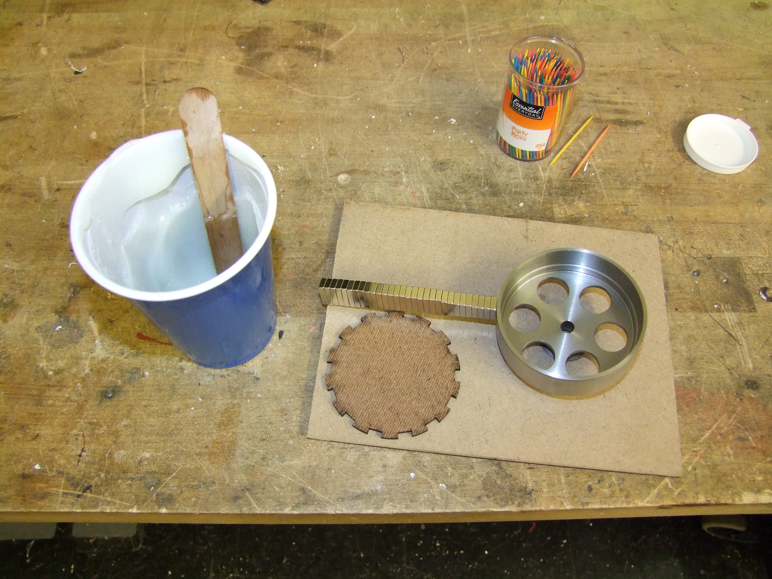
The stuff in the cup is some Aeromarine brand Epoxy mixed with a handful of colloidal silica filler. I don’t know what the actual amount was, but it looked like what I would have grabbed from the bag, but that stuff is sort of bad to come in contact with, so I used a cup instead. The silica filler increases the volume of the epoxy and makes it into a quasi-composite material for higher strength and space-fill ability. The mixture was made thick, so it won’t sag when I cure it on the radiators.

I laser cut a spacer to keep the first set of magnets in their proper spaces. This motor has 14 magnet poles, but each pole is made of two magnets. Two like-poled magnets really don’t like being next to each other, so I’m calling upon my old hub motor making tactics here. One set of magnets already solidly anchored will allow me to slip the rest in with ease.

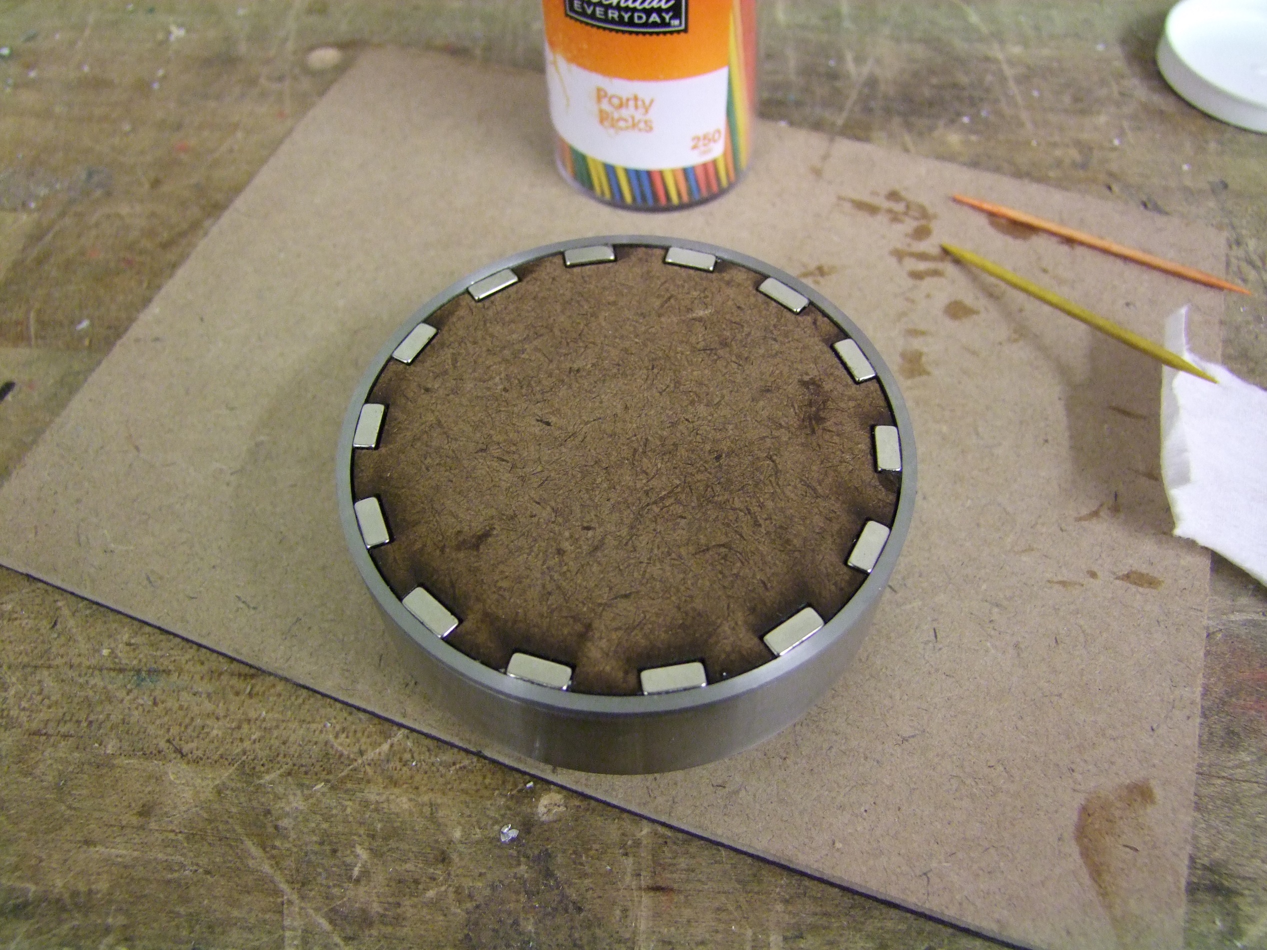
What the magnet ring looks like with the spacer attached. I left this to bake on top of one of the radiators in the shop, since it’s still UNACCEPTABLY COLD here outside.

The next day, I came back and shoved the rest of the magnets in. With another little batch of epoxy, I made big filleted ridges on the inside face (closest to the six holes) to prevent the magnets from moving, then shoved and filled in as much of the epoxy as I could into the small gaps on the near side. I hope the combination of this, and gently sanding the faces of the magnets to be glued, will prevent them from falling off. This rotor will be spinning a healthy 12,000 rpm or so.

Left to do on the motor include making the hub that the stator mounts on, as well as winding the motor itself. This is the first motor I will have made with less than 10 turns per tooth….

Next up, drive hubs. I decided to take a super simple modular approach to this and carve them out of some steel hex. Because the elements involved, such as the wheels and sprockets, are all flat, my choice to retain them along the hub is just retaining rings.

Each hub, therefore, just entails 6 grooving and a cutoff operation, plus the center hole drill.

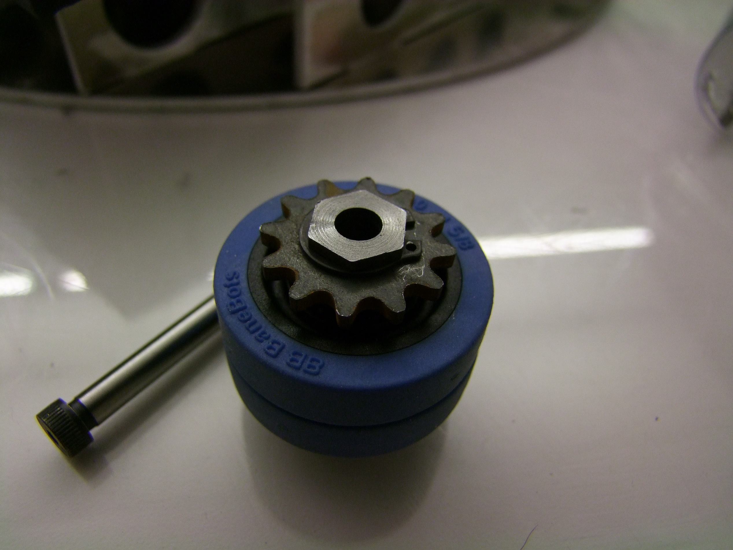
Here’s a completed hub, with the shoulder screw that will serve as the axle.

Soon after this picture was taken, I realized that there was nothing at all that I could tighten the shoulder screw against to keep the axle in the robot itself – recall the slotted axle mounting points. If I can’t tighten the shoulder screw, then the axle will just fall out. Imagine that happening in a match!

Oops – slight design oversight.

The backup plan is to open the hole in the hub to a little over 3/8″, and use a 3/8″ sleeve bearing over the shoulder screw as the spacer. Essentially, keeping the bearing stationary and spinning the wheel around it. There will be a bit more drag, but nothing an overdose of grease won’t overcome.
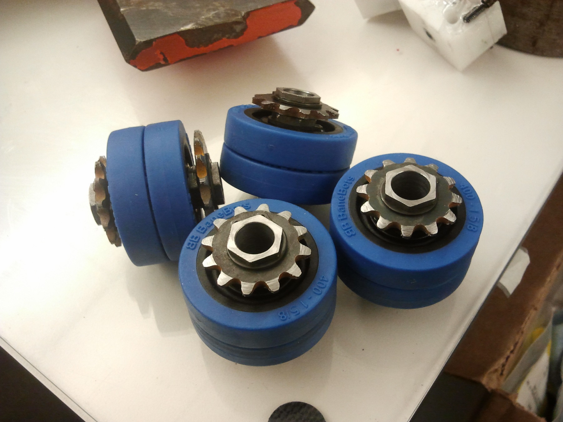
The plan executed.

I’ve also chamfered the sprocket teeth in this picture. The chamfer makes the tips of the teeth much narrow, such that the chain can stand some amount of misalignment. This is pretty critical to proper operation of chains and sprockets, especially if the tension can’t be guaranteed like the way I have it set up.

With the four wheels done, time to move onto something very exciting!

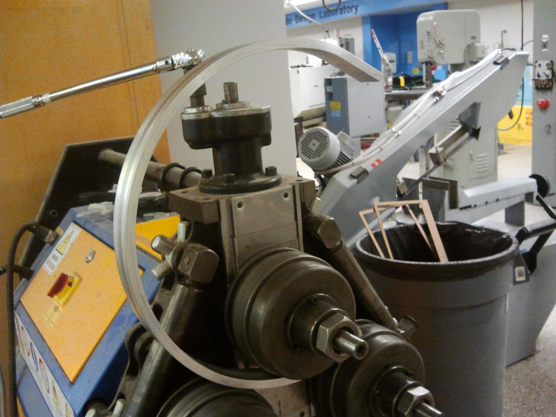
That started as a 5 foot long straight bar of aluminum.

With a powered roll bender, it becomes a 16″ hoop that goes around a certain not-quite-round robot. To form the hoop, I sized the bar with about 3-4″ of extra room on each end to accommodate the distance between rollers, and pass it back and forth between the rollers while tightening the center one each time. Gradually, the bar turns into a partial hoop.
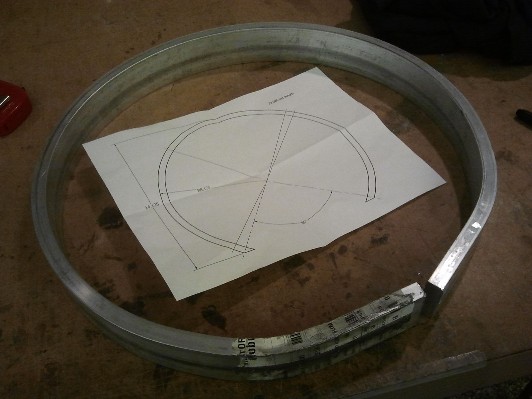
The finished hoop

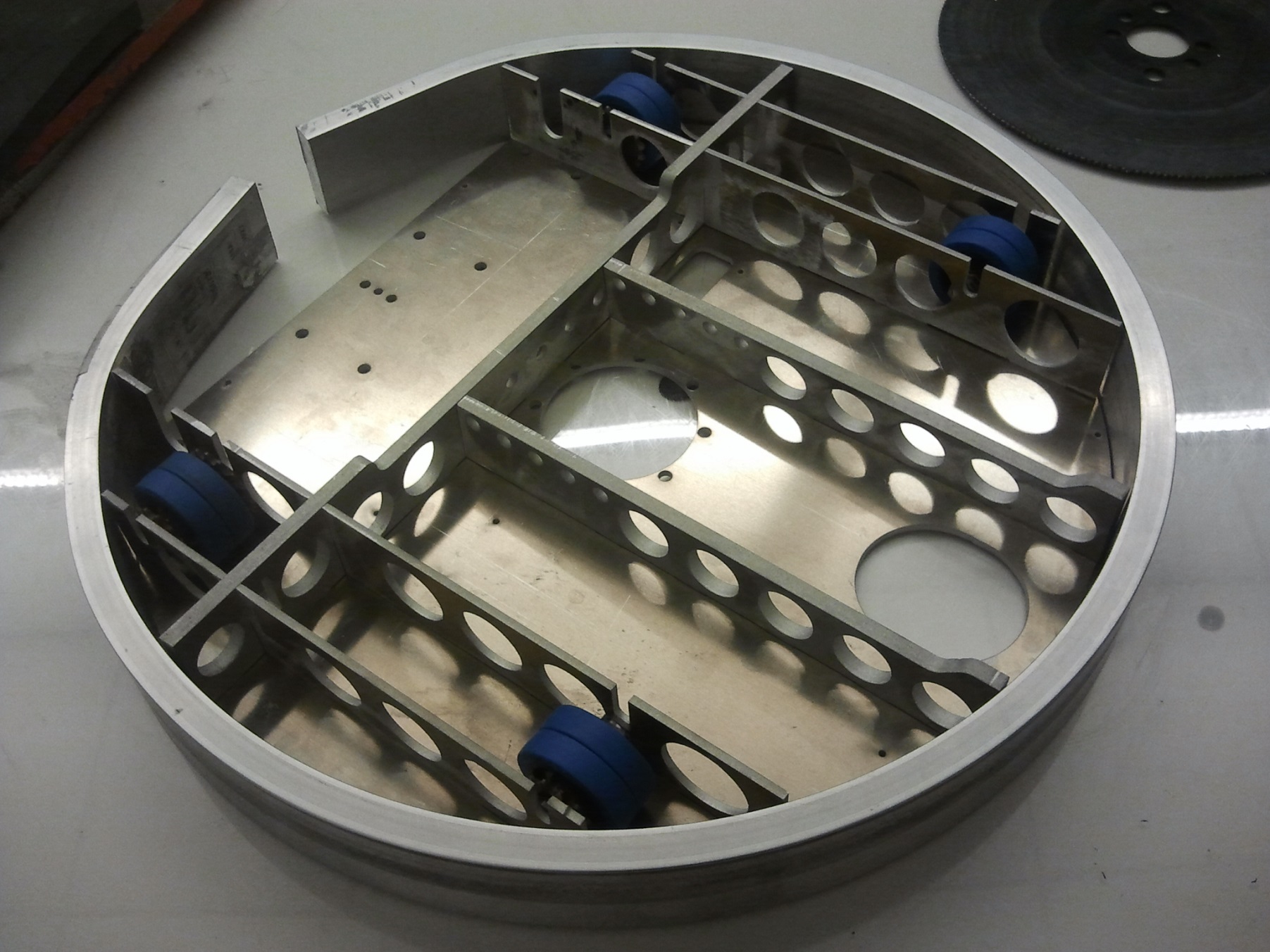
And with it stretched around the robot. Pretend-o-bot!

I need to cut off the ends and trim them to be flush next:

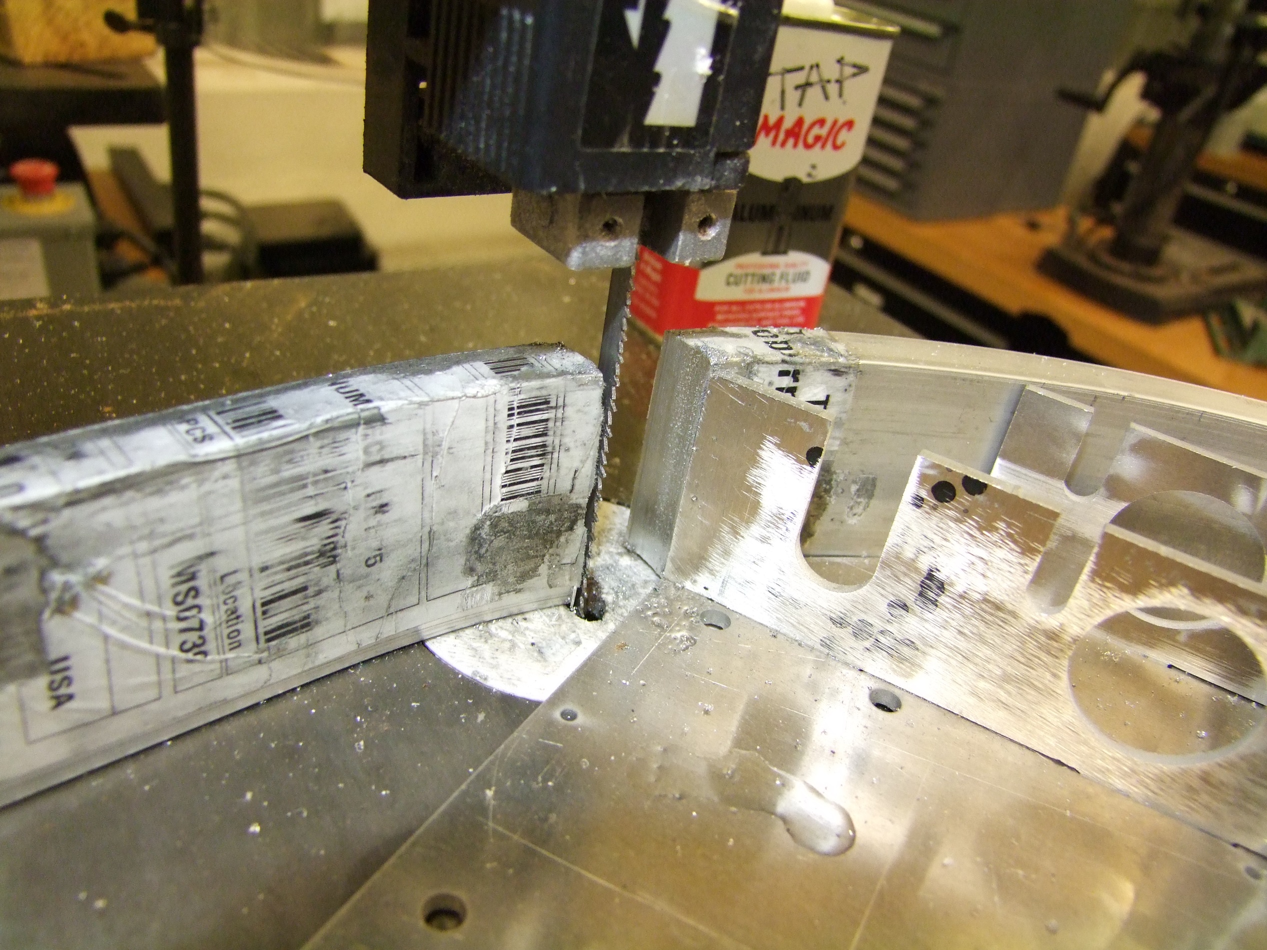
So I did it on one of the wimpy little Craftsman bandsaws I maintain in the shop for students to cut things like plastics and wooden dowels on.

Nobody can stand here and tell me one of those bandsaws can’t cut through 2″ of aluminum, because this took less than 15 seconds. It’s entirely about having the right blade, and keeping the cut lubricated. The blade is a variable-tooth 10-to-14 TPI bimetal type, and I kept pressure on the cut while squirting aluminum Tap Magic at it. Worked great!

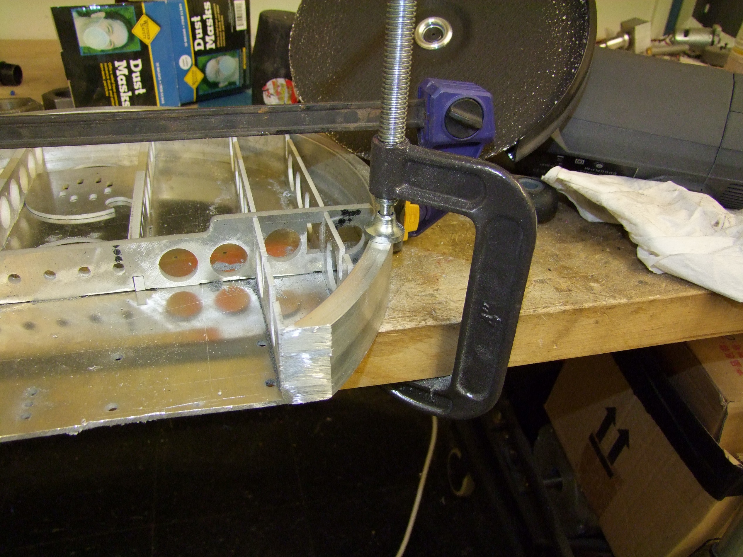
To trim the rest of the excess, I broke out the spare angle grinder I bought when appraising gear reduction methods for Chibi-Mikuvan. I have fully integrated this into a shop tool, available only to students who pass a battery of “Dear GOD WHY DO YOU ACTUALLY NEED IT?” tests. I had armed it with a set of both steelcutting and nonferrous-metal cutting discs, so I broke one out for this occasion. When in doubt, abrasives backed by gratuitous power tends to cure most ills. I cut vertically, using the face of the 1/8″ top plate as a guide.

A bit of belt sanding to fit the edge and the front plate could fit flush. I might keep sanding this to close the gap between top plate and front plate more, but the “using abrasives on an aluminum guide surface” part took more out of the top plate than I would like. This edge may stay unwelded or be patched with a small round bar.

I bent the front wedge with a standard metal brake.

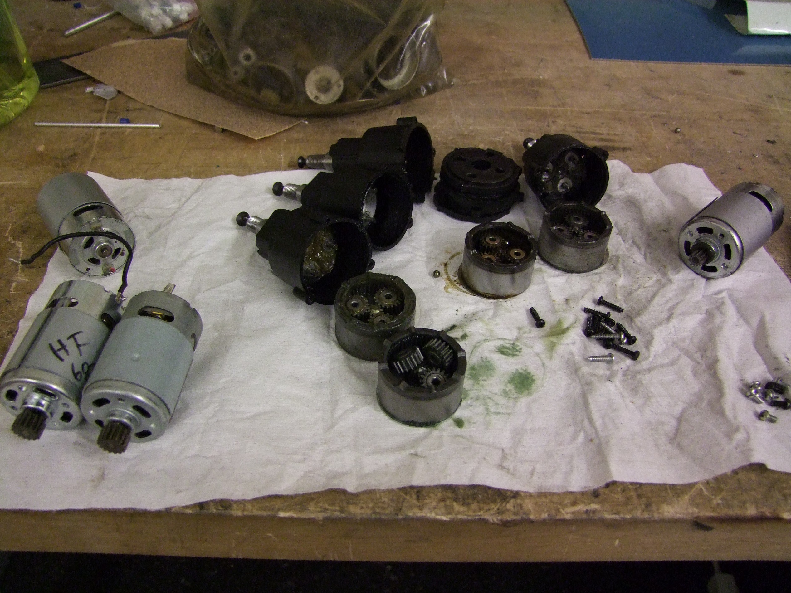
I moved onto finishing the drive motors. I’m staying with the 12 o’Clocker style “Angerboxen” design, which is a single-stage repackaged drill motor. To get the parts, I needed the following:

  • Two 18v native 550 size drill motors, to be supplied by Harbor Freight drills (Null Hypothesis leftovers)
  • Two 9 tooth pinions from a 36:1 drill gearbox, since the HF drills are 24:1. To be supplied by two random drill gearboxes on standby.

I took apart four drill motors and was amazed that between then were four different grease colors, plastic gear colors, pinion materials, and ring gear styles. Okay, China. Come on.

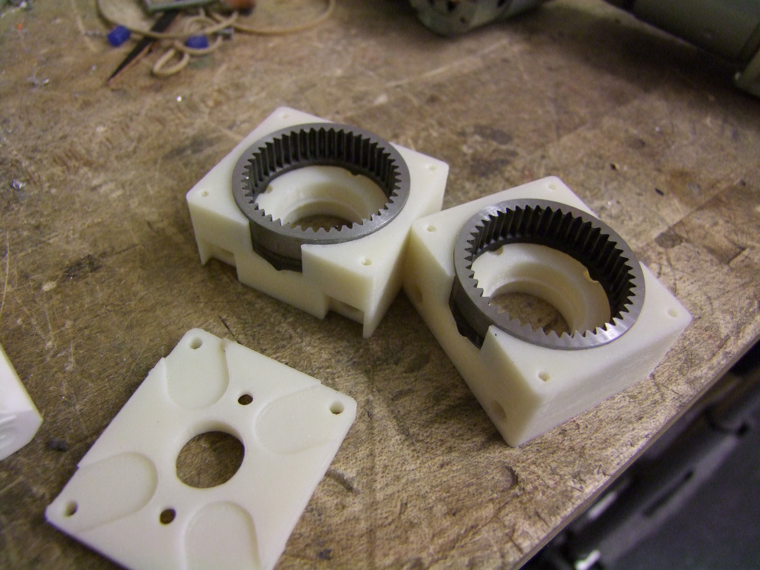
The gearcases, like on 12 O’Clocker, are made on a Dimension 3D printer out of ABS plastic. I carved off the ring gears on tinylathe.

(Try to tell me that this plastic is somehow worse than the shady nylon-like substance the original gearboxes were made from…)

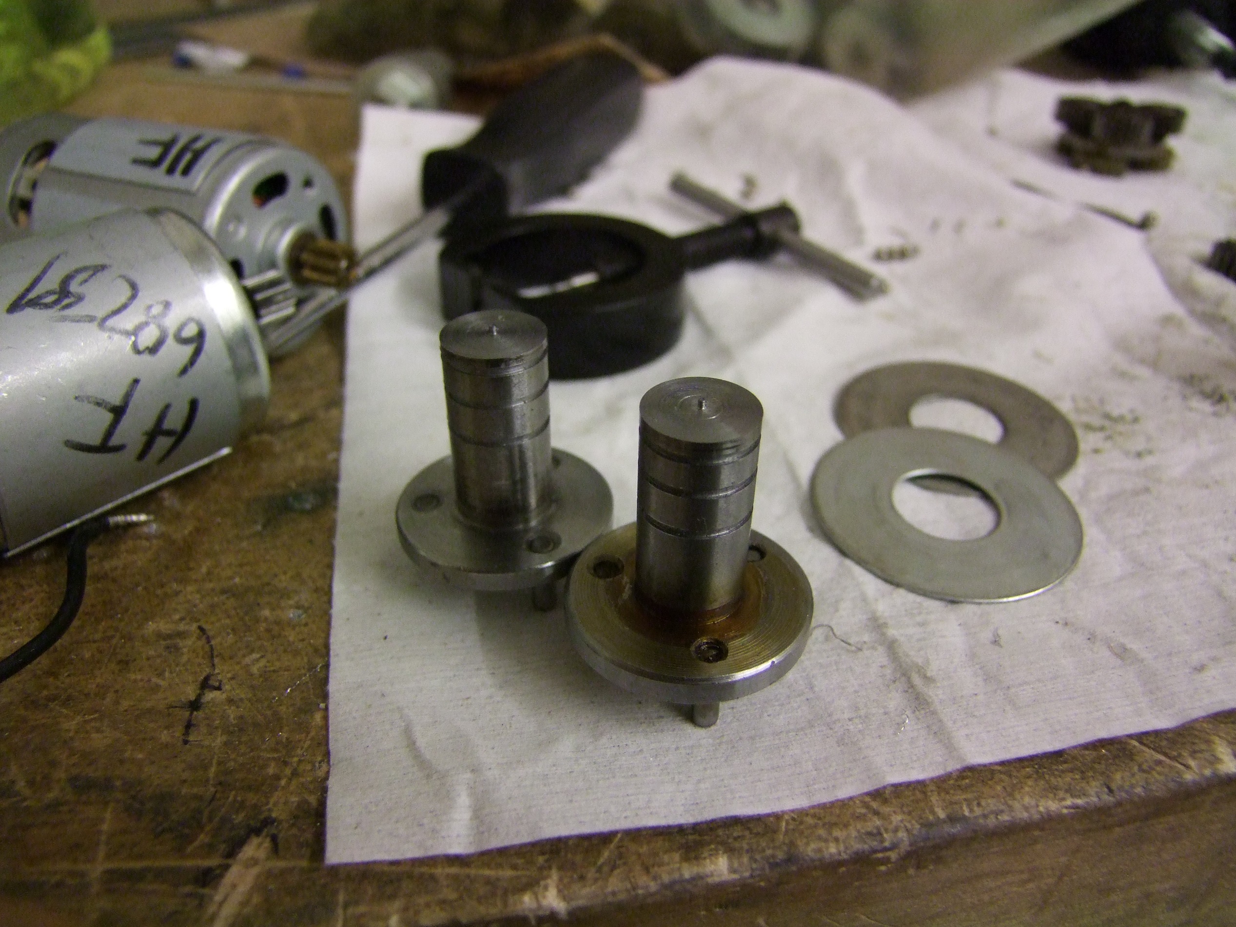
I recycled the drill spindles into the output shafts. Again, the output sprockets are retained by ….. retaining rings. I love the cutoff bar I bought for Tinylathe because the width of the tool is correct to service the most common snap ring widths I use:  1/2″ and 12mm.

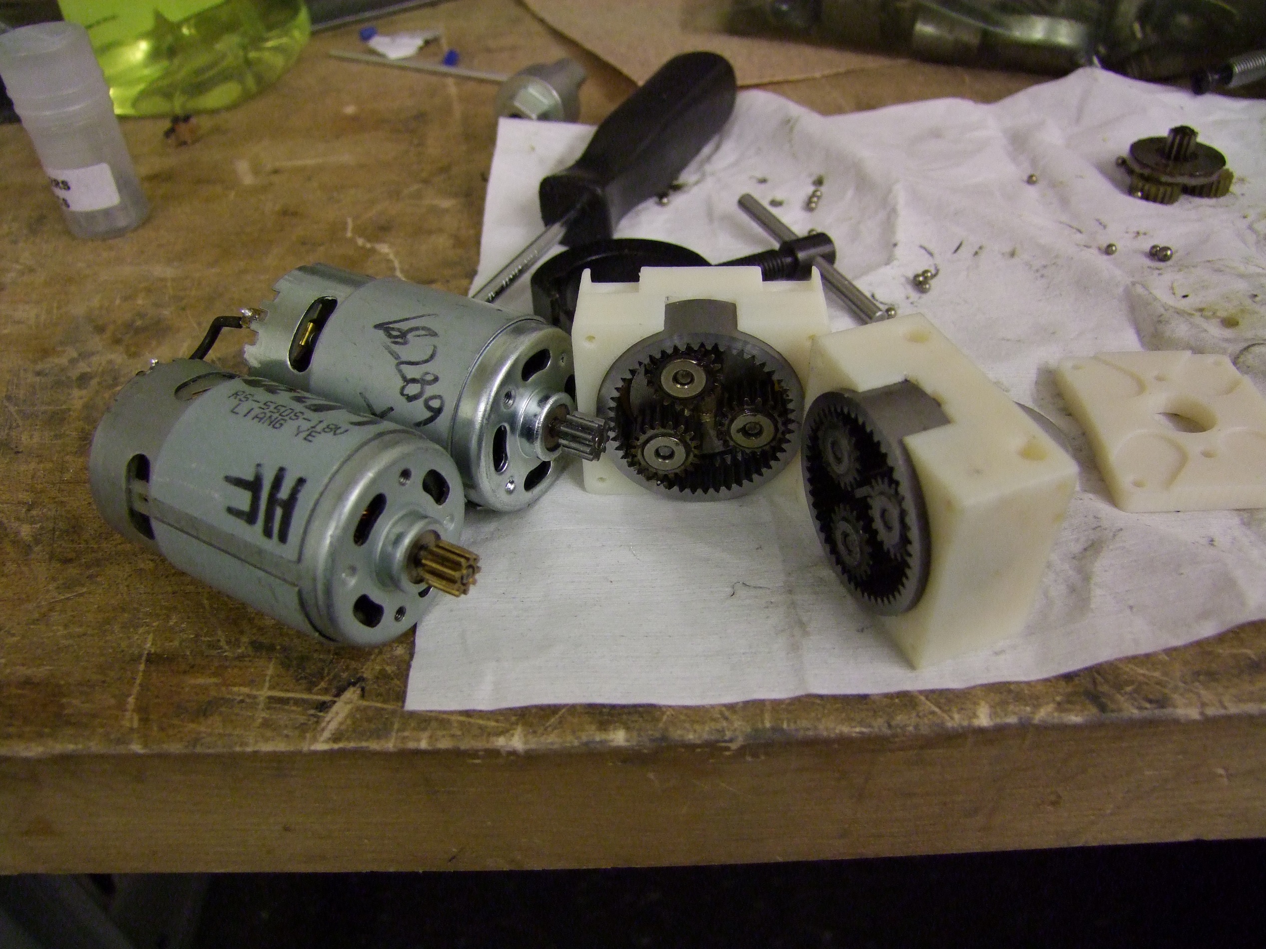
Here, I’ve used a pinion puller (background) to extract the 15 tooth pinions from the Harbor freight motors and replace them with the 9 tooth pinions from the other drills. Gearboxen have also been populated with metal output gears.

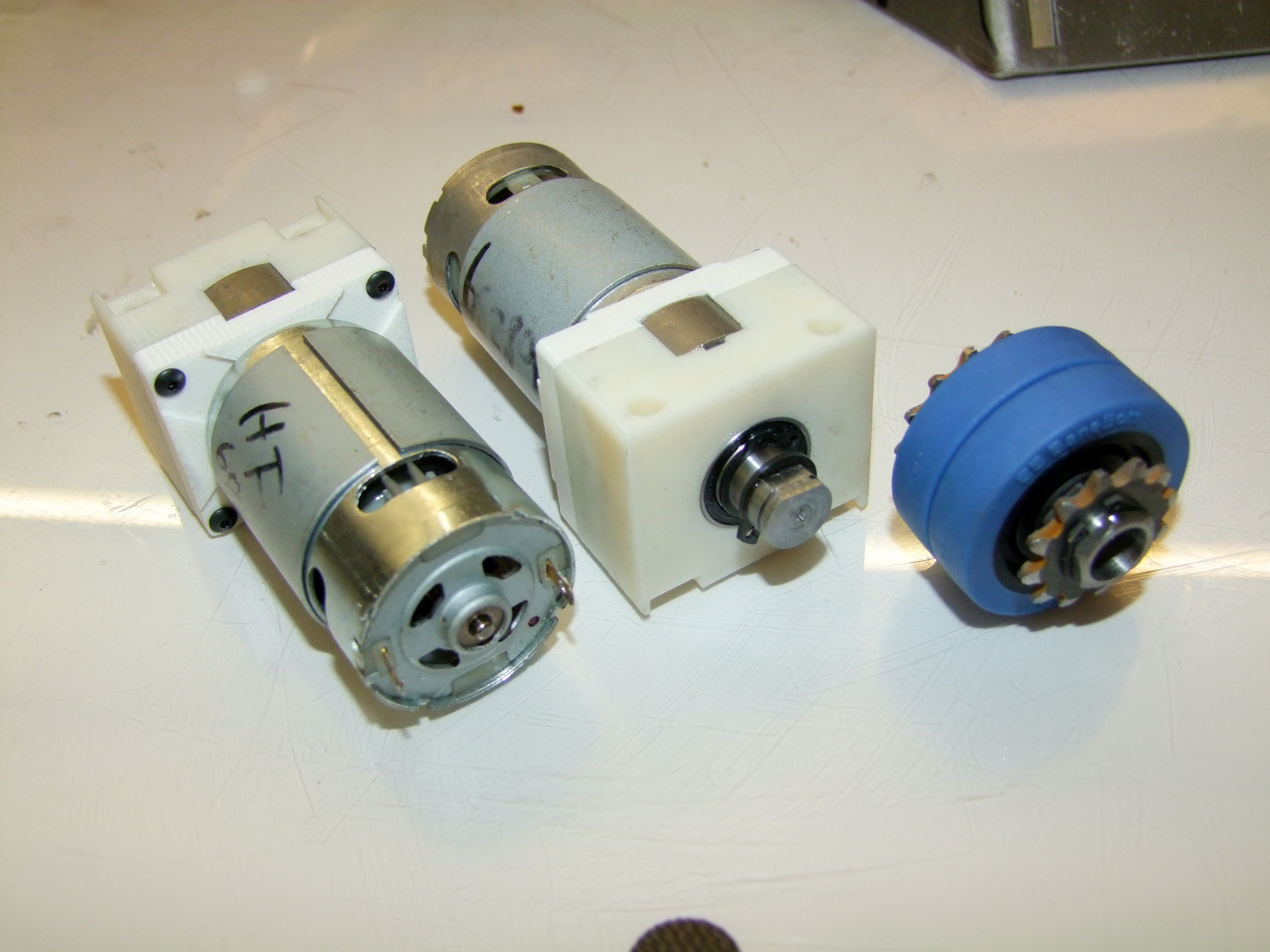
And here are the completed drive motors, after the D profile was milled onto the shafts. I have output sprockets, but they were cut improperly; I’ll need to remake them.

At this point, there are only 3 more major things to machine:

  • The big center spindle and bearing holder block
  • The blade spindle itself
  • The motor’s stator hub

Minor things to do include:

  • Make the battery retaining brackets
  • Wind the stator ahead of time

I hope to knock these out during this coming week, such that when the frame gets back to me, I can immediately start dropping components in it!

Returning to the Game With a New 30lb Featherweight: Candy Paint and Gold Teeth

My mental design-year can be broken up into roughly two halves: Dragon*Con season, which spans from roughly March to August, and Motorama season, which is basically September through the next February. Of course, the observant would notice that these things seemingly coincide with robot tournaments.

But that’s kind of how it works. After each big event, I start thinking about what I want to do for the next. Robot fighting is a game which I do not foresee getting old for me for a very long time to come. And why should it? Of all the things I ever became involved in, besides being the first one over 12 years ago (…) , it’s the most freeform and unburdened by pages and pages of rules and procedures. Run what you brought, not what the organizers say you have to bring. It’s very much a high-energy (… literally…), destructive, and kind of redneck sport, and there’s no whitepaper to write at the end. I have literal dozens of sketched out designs that will likely never see the light of the day unless I drop everything and become a professional robot cockfighter, which I would love to do. Here’s just one.


Someone get on that right now. Build it so I can live vicariously through you!

But I digress. It’s been Motorama season for a while, and so my off-duty mental cycles have been devoted to engineering the latest entry in the Imperial Carolingian Robot Army’s Register. May I present CANDY PAINT & GOLD TEETH:


Wait a minute. Hold on, trap. That’s a giant spinning weapon, not a fancy multi-axis grabby thing. The hell is wrong with you?

I’ve  been out of the high-energy spinner game for quite a few years. My last “large” kinetic weapon was Trial Bot, all the way back from 2005-2006. That design wasn’t very effective, so it was retired after only one event. I’ve built quite a few successful weaponed 3lbers such as Nuclear Kitten (and its earlier versions), plus Pop Quiz which was successful Back In The Day. Overall, I haven’t been enamored by the big spinning chunk of steel like many competitors have been, choosing instead to focus on drivetrains and manipulator type weapons like lifting and grabbing weapons.

With the flooding of the hobby R/C marketplace by Chinese components some time in 2004-2005, the spinner game began getting ridiculous, with each wave of new bots combining a larger brushless motor with a larger hardened steel weapon of some sort. The arms race began being lambasted as the “brushless penis race” as most of the competitors were young men, and most of the successful designs were the same in concept and execution, only differing by how big the spinning toothed drum or bar was.  It got to the point where many matches were just a minute of robots hovering around each other, each aiming to deliver the match-ending hit, and finally a weapon-to-weapon hit that destroyed both robots or left them totally disabled to the point of only being to crawl around on one wheel.

It was, to borrow a previously used analogy of mine, like we were all dubstep groupies waiting for The Drop… or in this case, The One Hit. The only other bots that could survive were armored bricks which kept running into the spinner until something, one or the other, broke. I did not find this game very interesting, and ultimtely neither did quite a few builders, who began exiting the game after their last bots were exhausted, because it was getting expensive to rebuild over and over robots which were good for only a handful of matches, or even just one. I in fact retired Test Bot out of the 12lb class after it was “penised” at Motorama 2008. That year also saw the first Überclocker.

Several efforts sprung up to counter this, including the Sportsmans’ Class which I found as slightly reactive but ultimately aligned with my own goals of repopulating the ‘middle of the spectrum’. Back in the very old Battlebots days, the power to weight ratios of entries was so low that matches were more determined by driving skill, strategy, and reliability, than dancing around gyroscopically waiting for the right impact to land. This greatly contributed to the corpus of weird or interesting designs (check out the old Team Nightmare event pictures). In the current Sportsman’s class, flippers, hammers, and the odd clamp-and-lift or two (ahem) have all returned. The matches tend to go the full length and feature a lot of action and driving, with the added bonus that you could generally return home with something that did not require a dustpan to pick up.

It’s been a while, however. I miss the feeling of beating something with a chunk of steel. That’s where this design comes in.

There’s been relatively few successful overhead-bar spinners, known in the vernacular as “Hazard-style” after the multi-time Middleweight Battlebots champion. This type of design is hard to get ‘right’ because the blade tends to destabilize the robot if it’s too long or heavy, and then it’s more difficult to self-right if it does go over. Pop Quiz and Trial Bot are both this style of bot, so I have a historical attachment to this design too. Other examples of this design are Brutality

and Tornado Mer, which early versions of this design resembled the most.

Note that all these videos are from quite a long time ago.

I wanted to try making a bot that wasn’t square. Using a continuous round tube for the outer armor was appealing because it presents no obvious weak spots, unlike a square corner (or the backside of Brutality’s front wedge). I fixed the blade size at 2 foot span, 3″ wide, and 1/2″ thick, a relatively solid dimension that ended up being  almost exactly 10 pounds in steel. This dimension has been my ‘default’ go-to for a weapon of this size. A chunk of S7 tool steel typically costs about $100 in this size. All things considered, this thing was basically a small Tornado Mer.

The design goals for this bot were basically:

  • Be round.
  • Be reliable, over packing sheer energy

I started with the “doodle assembly” in which I haphazardly make parts and outline sketches.


 The size of the bot was dictated primarily by what size giant tube I could easily find and purchase. Yarde Metals had a few promising candidates in the form of 15″ and 16″ tubing, so I started with 15.  The rectangles represent the outlines of components I wanted to use. At this point, the choice of drive motor was a set of Banebots P60s with some 500-class DC motors. Fairly vanilla, and would give this bot an average drivetrain power for a heavy weaponed 30lber.

I experimented with several different possible heights, shooting for a 1.9″ blade height: 1.5″ wheels, 3/16″ ground clearance, and then a little over that to make sure I don’t whack myself. I’m used to sacrificing COTS parts for smaller packaging – Pop Quiz is still one of the lowest blade height antweights extant and for a while was the absolute lowest, and Trial Bot also had a blade height of 2.2″ using 2″ wheels.

The robot height decision was tied in with what I wanted to drive the weapon. Initially, I was inclined to make a super-wide custom direct-drive motor for the weapon – which would turn this bot into a giant Pop Quiz. One plan was to start from a chopped quadrotor motor on Hobbyking, except add external ring bearings (or metabearings – support rollers) to make it stiffer. I also took apart the 8-FUN motor again to measure the stator and considered using the motor inside as-is.

Further thinking and discussion led me to go for a brushless scooter style high-reduction indirect drive. I figured this bot was going to spend a lot of time upside-down and possibly crammed into a corner. A direct drive motor wouldn’t be as deterministic in such a scenario unless I also ran a sensored controller and used Hall sensors, which I didn’t want to do for reliability’s sake – one more part to jostle loose or break off its solder joints. The first image still shows a pretty insane and almost impossible (due to lack of tooth engagement or minimum pulley radii) and unnecessary 10:1 reduction. I put in a ~85mm motor diameter as a placeholder, since it was pretty clear that this had to be a custom job.

More components have been added here, including the outline of a Ragebridge as well as batteries. Height was the most important criterion when choosing batteries for this thing, since I would only have about 1.25″ of space to put them in. I elected to run an 8S power system with two 4S packs wired in series. My voltage philosophy is generally to run as high of a voltage as I can reasonably do so to minimize current draw and wire size; 8S was about as big as I could get without dangerously overvolting the average 12-18v RS550 motor. This high voltage would allow me maximum flexibility in choosing the weapon motor winding to best match it with the physical gear reduction.

I ended up deciding not to spend another $100-150 on batteries, but to use up more of my Nuclear Arsenal. I was going to split up two Thunder Power 7S 4.4Ah packs to make two 4S ones – two of them have dead cells, so they are not useful by themselves any more. 4 cells from those packs gives me a pack 30mm tall, or pretty much my maximum allowed height, as well as a great deal of battery energy for match length and number-of-spinups overhead.

The reduction is still shown as a slightly less ridiculous 8:1. I was also settling on what kind of power transmission to use:

  • It needs to not stretch – or at least do so minimally, for consistent power transmission properties
  • It should be rubbery, ruling out chain drive. A metal to metal coupling would be kind of asking for breakage.
  • It shouldn’t have teeth, because the high ratio I needed implied a small pulley, tight wrap, and therefore high tension in the belt; plus extreme impact loads.

I decided to give good ol’ V-belts a shot. V-belts often get written off as old technology, but they have favorable properties for this sort of thing – they allow some innate slippage due to the lack of teeth and do have tension members (they’re not just loops of rubber). The “L” series of belts (2L, 3L…) held promise for me since they’re designed to be small and flexible. A 3L belt seemed the best candidate here – 2L belts are tiny (1/4″ wide and 1/8″ thick!) and 5L is getting on up in huge. A 3L belt is 3/8″ wide and a little over 1/4″ thick, and the empirical smallest-pulley in use seems to be around 1.25″. Many larger bots have (and still do) use them for weapon drive, but they are not common in the little bots usually because of the minimum pulley diameter and thickness.

So naturally the next thing to get modeled is the Epic Drive Pulley. This shows the next weird thing on this robot that’s been getting me some stares. I’m electing to go for a live (rotating) axle suspended in dual tapered roller bearings rather than putting a hub and bearings on the blade, and only having a solid pole on the robot.

The latter is a mechanically simpler system, but in my opinion a live axle in this case saves both weight and height. With a hub and bearings that stick up above the blade, the center of impact force reaction is far up the shaft, which needs to be large in diameter and mounted solidly in the center of the bot to handle it. If I’m going to have a big solid block in the center, then I can put bearings in it instead, and move the center of impact much lower as a result. I also lower the blade height substantially doing so.

The big pulley is actually going to take up a substantial portion of the underbody real estate of the bot, since it’s on the other side of the bearings (to save, again, blade height). A lot of components need to fit under it, which ties into the 1.25″ of available workspace issue I raised earlier. This is what the blade spindle assembly looks like, in section; excuse the CAD-ahead going on:

Note the presence of Belleville washers on the top and bottom. These are often used to preload tapered roller bearings for zero-slop operation. In this case, I’m using the bottom washer for bearing preload (it pushes the bearings together, against the shoulder at the top) and the top big washer is only to keep the blade on. This keeps the bearing preload nominally separate from the preload of the blade. The idea is that the preload force has to be overcome before any of these parts even think of moving, and with (hopefully) most of the impact forces being side loads, it should prevent “blade wobble” from shaft compliance.

Now, in a good hit, everything will probably just munge together, but hey.

Back to the proper CAD order:

The internal frame rails were made using a “master sketch” that I reference all the solid models from. At this point, I didn’t know what any of the spacings or sizes needed to be, so I could just adjust the master sketch and the rails would resize to fit. The first time I did this, I made a sketch in the assembly; turns out Inventor doesn’t allow those kinds of references.

So I had to start over and make this sketch in a separate part and the insert the part into the assembly, letting other parts become Adaptive off of it. End random Autodesk Inventor tip.

Whoa, getting a little ahead of myself here.

After liking where the rectangles ended up, I began importing parts from previous robots and inserting them. The P60s are shown, as is the drive wheel solution: Banebots wheels on custom hex hubs, running on shoulder screw dead axles. I’ve never used Banebots wheels before, but they seem to be solid for a lot of other builders. The available of a hex bore was the swaying decision here, since it reduced the “hub” to a chunk of hex steel with a few retaining ring grooves cut into it.

To get power from the offset motors to the wheels, I have one stage of very short chain joining the motors to the rear wheels, and then another 1:1 stage from the rear wheels to the front wheels.

At this point, the protoform of the weapon motor has also been modeled for visual fitting.

This is the motor in a more complete form, though still showing the unrealistically sized 0.9″ pulley. Basically a one-sided hub motor with an integrated pulley, I’m going to blast it out from a solid round. No, not a two-piece welded assembly, nor a stack of waterjet-cut rings. I have a 3.5″ steel billet that’s been sitting around for far too long.

The magnets are the same ones used on the first iterations of Razermotor, sourced from Supermagnetman. The stator is also a leftover from the RazErmotor days, a 70mm copier stator that’s 15mm thick.

It sits on a 8mm shaft that rides in conventional 608 skate bearings. The very short load-to-bearing distance makes me confident that a good quality 8mm shaft (read: not made of the bullshit I make standoffs from, but real shaft steel) is sufficient for this motor; it’s also going to be hitting 12 to 15,000 RPM, and a bigger bearing would suffer.

A pizza appears.

The motor mount has a gratuitous number of slotted holes to let me adjust the belt tension if needed, but also maintain rigidity in the area.

This bot is of an ‘upside down’ construction. The top plate is rigid and integrated into the one-piece frame, and there’s only a bottom ‘dust cover’ which will be made from 1/16″ FR-4 (Garolite) laminate for the electronics. The batteries will have a bracket to retain them, but this is not shown yet. Basically, not a good idea in the old Battlebots days of floor-mounted hazards. I went this way because I didn’t want to have to remove the blade over and over to do maintenance. Everything in this bot drops in from the bottom and is bolted in place.

I also went to ‘duallie’ Banebots wheels because the single 0.4″ wide wheel seemed too fragile. These wheels have a thin web portion before they fatten up for the hub again. The chances of the bot landing on one side (or one corner, hence on the wheel) and breaking that off seemed fairly high. What I’ll likely do is put the two wheels side by side with filled epoxy in the middle to fuse them permanently into one.

A view from the top with the top plate made transparent. Buttonhead screws are shown, though for blade clearance issues, these must necessarily be flatheads in real life.

The design stood like this for a few days. I was satisfied with the roundness, but did not like how much wasted space there was inside. I needed to match the largely rectangular parts inside with a circle on the outside. I guess that’s just a trait of round robots.

After a while, though, I decided to refactor the design into one that was more practical. The roundness makes the bot more visually cohesive, but it is not very practical. I wouldn’t be able to push very well as a last-ditch backup, and being fully round is counterproductive for self-righting – a lot of it depends on luck and physics from jouncing around on-edge. A fully circular bot like Tornado Mer tends to “coin” around (though in that match it didn’t help that the weapon motor contactor locked on…)

I started playing with adding indentations or other features to the design:

Attempt number one: Cut off a chunk of the circle and append a polygonal wedge to it. Simple enough, and it would get the job done, but I didn’t like the fact that the two end corners were exposed. Sharp internal corners on this design would present an unnecessary vulnerability to opponent weaponry, since it would otherwise tend to bounce off the round sides or up the sloped wedge surface.

So I tried a ‘wraparound’ wedge instead. The wedge is not formed to the rounded surface at the corners, but is just tangential to it for a duration. This seam will be welded shut so it will resist peeling.

I liked this design a whole lot more, so I went with it:

Five front gussets support the wedge. I had to rebuild most of what was the rear end, including new cover plate shapes and motor locations. The battery cage has also been modeled – it comprises two 1/16″ aluminum folded sheet metal assemblies that each trap one modified 4S battery pack.

I decided to change out the motors entirely. Previously, I was planning on running a single-stage 5:1 P60 gearbox; however, their length and mass became issues. Plus, I’d have to buy them. Taking a page from 12 o’clocker’s “Angerboxes“, I modified the design to mount from the top down. The drill gearbox is a 6:1, yielding me a little reduction, so I could back down on the need to externally reduce from the intermediate chain stage. The simpler design saves a few ounces per side. Even though they’re plastic-cased, I think a well-supported motor (see the black rear mount) and use of the material in bulk will be sufficient.

The drivetrain is designed to hit 15mph, which is pretty zippy for a heavy weaponed bot.

A size comparison next to Überclocker, which it would bang up pretty badly. Clocker is a pretty good example of a design with too many pointy bits to survive in a big-weapons environment. At the very least, the clamp arm would have needed to be more vestigial to allow weight for a big armored plow in the back.

Physical progress-wise, I’ve accumulated the majority of parts for the bot, and more are on the way. First, a few weeks ago, I snagged these old weapon blades from a lightweight (60lb) bot which were reused in a 30lber years ago. They are…. 24″ long, 3″ wide, and 1/2″ thick, heat treated S7 tool steel with 1 inch bores. Exactly what I was designing! Well, that pretty much seals the blade decision.

The bottom one is solid, weighing 10.2 pounds exactly as it should, and the top has been weight-reduced to around 8 pounds.

I should be able to run the solid one; as-designed, the robot weight is 27.6 pounds, not counting some small hardware and wiring (which always adds up).

Most of the frame parts cut out of 1/8″ and 1/4″ aluminum. Caveat: I’ve only welded aluminum once and it didn’t go over too well. This will surely end well.

A few pieces are missing, so I can’t start just yet; I’m hoping to wander into the machine again this coming week with more parts for other bots.

However, I did sand and fit the rest of the pieces together. Pretend-o-bot #1 is complete!

I’m hoping to be able to roll the big outer hoop this week from barstock. I purchased two 1.75″ wide, 1/2″ thick 5 foot extrusions to make the hoop – only one is needed, but it was cheap and I’m most likely going to bang it up at least once.

I’ve been probing the local peer cloud to see if there are any skilled aluminum welders willing to take this job up. As much as I would like to learn on this bot, I also kind of don’t want to have it shatter on the first hit! If not, or if I’ll have to pay an absurd amount to get it done, well… here goes nothing in particular.

I’ve also gotten:

  • The first boatload of McMaster hardware
  • Motor magnets
  • A pile of Banebots wheels, since a full set of wheels plus spares on this thing is like 16 wheels.

Parts that are already on-hand and just need to be modified or pressed into service:

  • Ryobi drill motors. I purchased these from a parts distributor (p/n 984572-001) on the recommendation of a few veterans of the community. These are basically Harbor Freight drills but much higher quality.
  • The 7S 4.4Ah Thunder Power packs with dead cells, to be reworked into 4S packs
  • The copier motor stator

I’ll still need to machine:

  • The one-piece rotor for the weapon motor
  • The stator mount for the weapon motor
  • The epic block of bearing-holding at the center of the robot

As for the giant output pulley, I did a make-or-buy study as soon as the design was finalized: I threw it on MFG.com, my go-to for hiring shady Chinese job shops to machine things for me (things made through them include all of the DeWut gear and my small run of hub motor parts). I will hopefully have the finished result back by the end of February – but if shit goes down, I’m going to cut out a circle from 1/2″ plate, stick it on a mandrel, and go to town.

In the next episode of Big Chuck’s Automotive Blog…