Operation Bad Timing II: Chinesium Rising; The Zero-Delta-Entropy Point

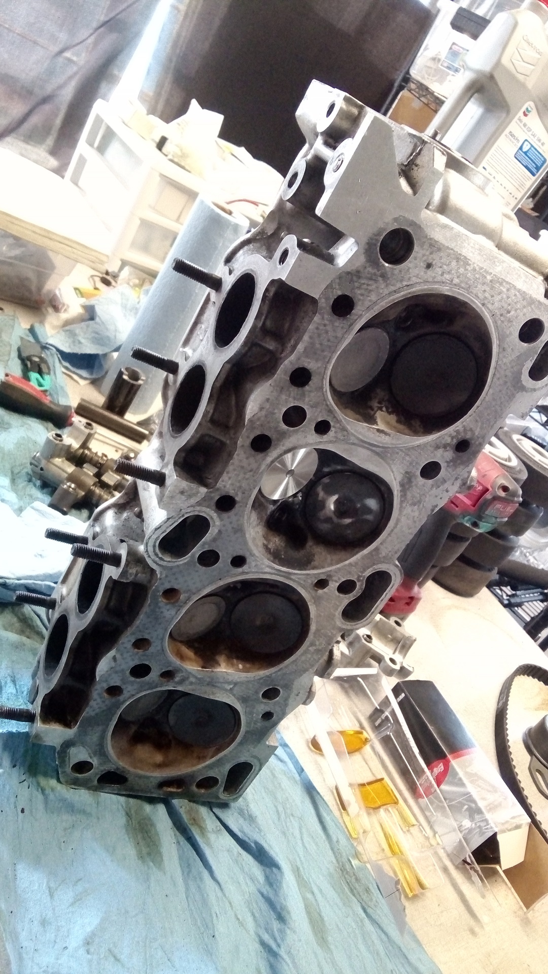
Last time, I had just gotten to replacing most of the seals on and cleaning up the old head before discovering a cracked exhaust valve which meant I couldn’t put everything back together before getting new ones. That delay pushed back the timeline just long enough for the Chinesium Solution to appear:

Yep, it’s cylinder head shaped alright.

– me, when I opened the box


To recap, while searching the neighboring galaxy Craigslist for old Mitsubishi truck/van parts, I discovered that there is still a lot of Chinesium aftermarket support for this engine family, the 4Gxx series. So I took a leap of faith and spent $400 on a complete cylinder head assembly, in the interest of exploring the solution space and documenting it for all other silly van enthusiasts as I tend to do for everything.

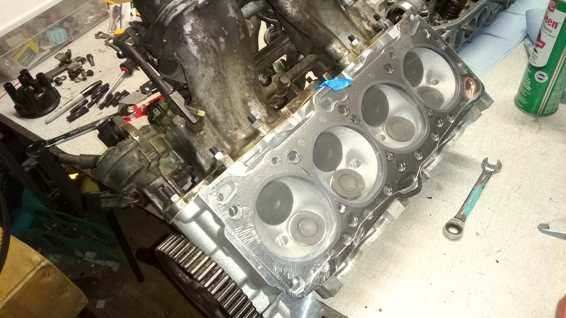
The appearance is virtually identical to my current cylinder head, minus one or two things which jut out in the corners, possibly for different accessories or mounting needs later on. However, the biggest added feature I noticed? Roller rocker arms! That’s worth at least like 1 horsepower over flat ones, which to me is a 1% gain.

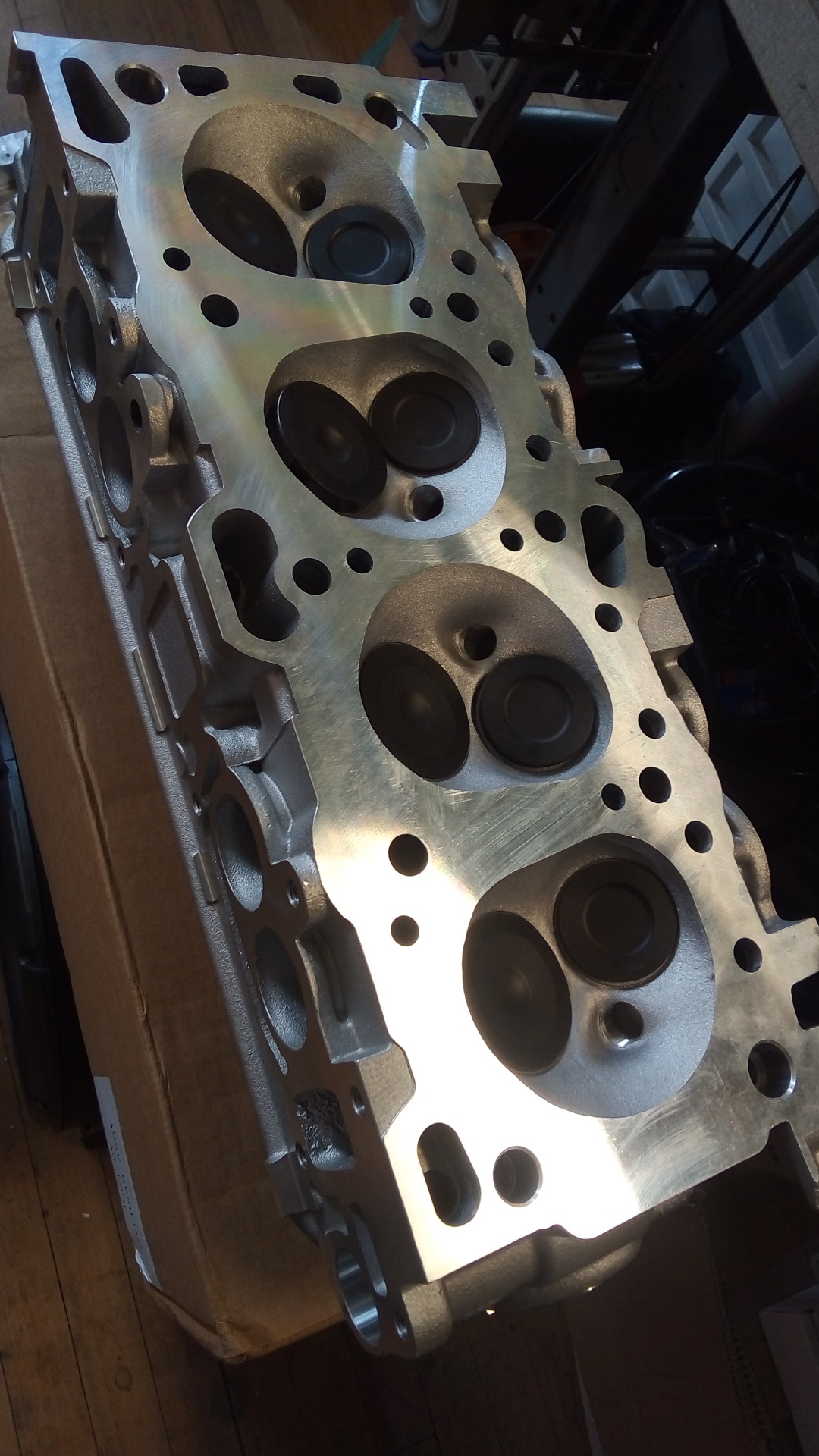
The gasket-mating surface of the head is otherwise identical.

So now I’m left with a conundrum. Which head do I use!? The old one is proven and has most of its wear parts changed already, but I had new valves coming and would be changing those out, but without refinishing the valve seats. The Chinesium Option is brand new – late-2017 date code on the casting and still smelled like machining coolant – but my fundamental skepticism of Chinesium persists.

I figured that at the end of the day, all things considered, Chinese people also prefer to have working cars – so this thing probably doesn’t not work, but might have parts that have  shorter wear lifespans. However, I’m of the opinion that any new parts I can find for this thing are already Chinesium, or already will not have the expected lifespan of an original Mitsubishi OEM part, or both. For example, the head comes preloaded with valve stem seals which might wear out again at the 50-70K interval. Or they might not. Who knows?

Fact of the matter is, after doing this dive, I’m no longer uncomfortable and scared of a lot of the process, just understanding that it takes time. So what if this thing instantly and catastrophically fails – lesson learned, shove the old head back on. So for now, I’m keeping the old head around until the new one either proves itself or doesn’t.

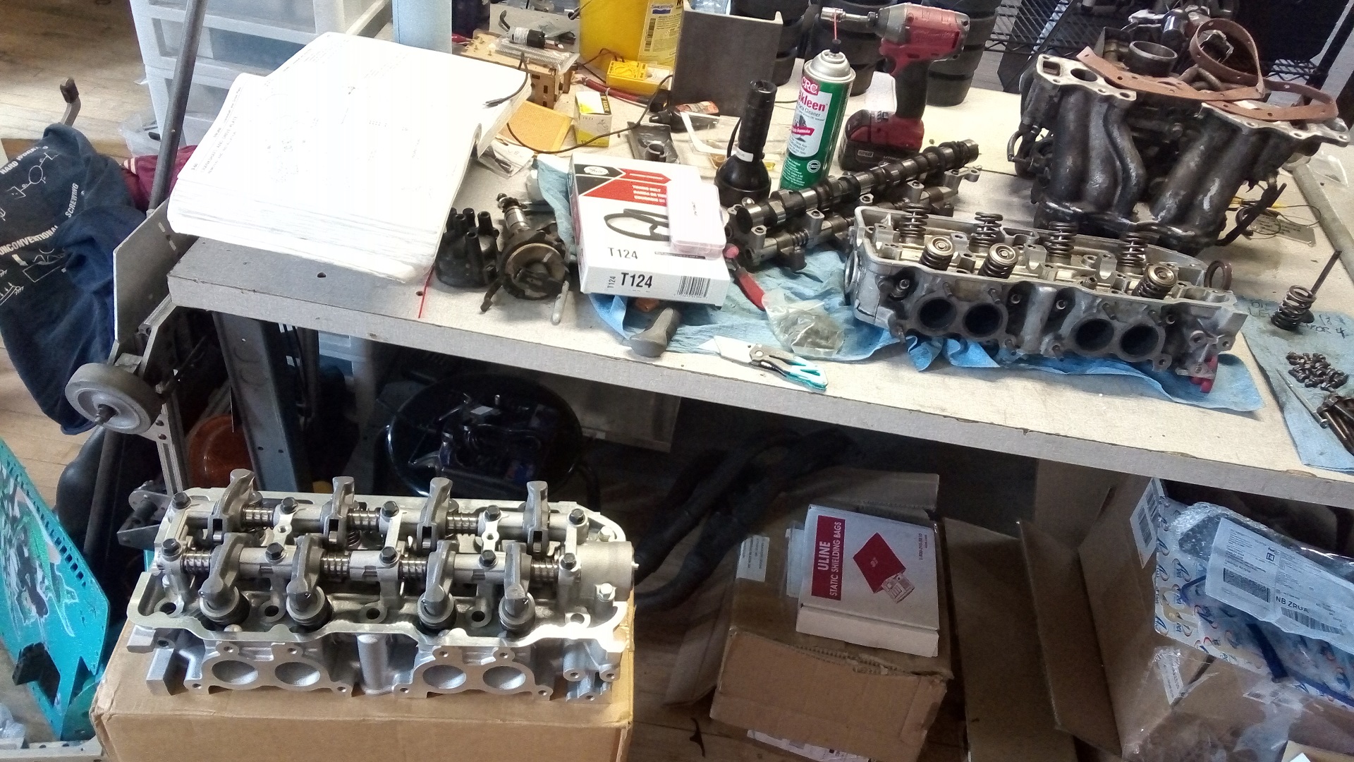
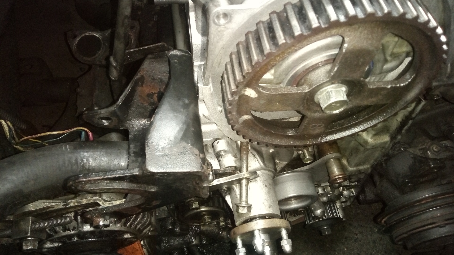
And so we cross the point of maximum entropy, basically when your shit is the most taken apart and hopeless.

The new head even came with studs. I picked up a pack of new metric nuts to replace the hodgepodge of hardware that was on the old intake – which I still can’t figure out if it was factory-intentional or the result of some previous surgery.

This was the moment I discovered that JIS (Japanese Industrial Standard) and the rest of the world has different wrench sizes for various fasteners.

Chances are, in the U.S., if you even touch metric at all, it’s the ANSI or ISO standard. JIS is Japan’s own thing, and it has different head sizes for nuts and bolts. I finally understood why some times I found M8 nuts and screws that had 12mm hex heads and other times with 13mm ones, or more drastically, M10 nuts and screws with – get this, 14, or 15, or 17 millimeter wrench needs. I took most of these parts off with a 12mm wrench… but a 13mm is being used to re-arm them!

To be super authentic and ジェイ ディー エム, I’d have to hit up the local metric automotive supply place and get some JIS small-wrench hardware. But McMaster-Carr is just so easy.


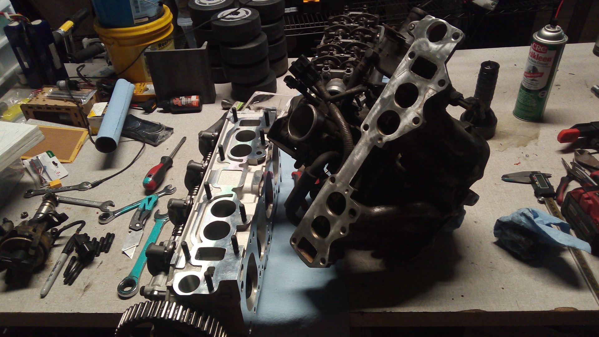
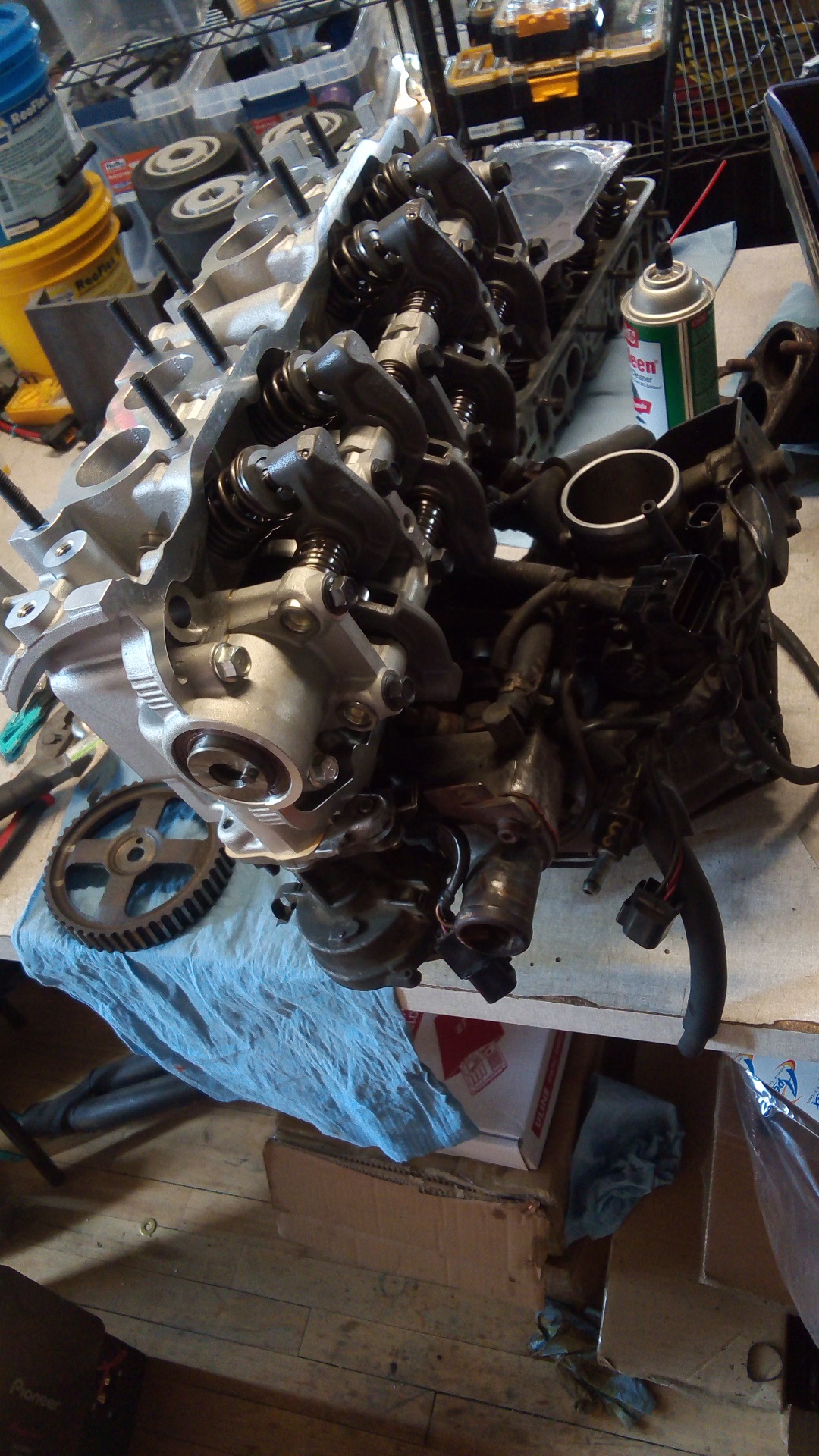
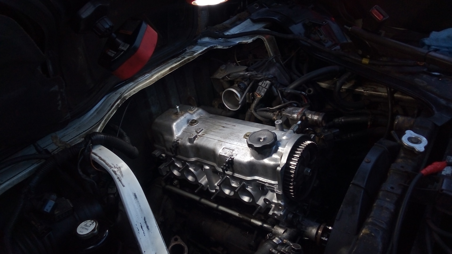
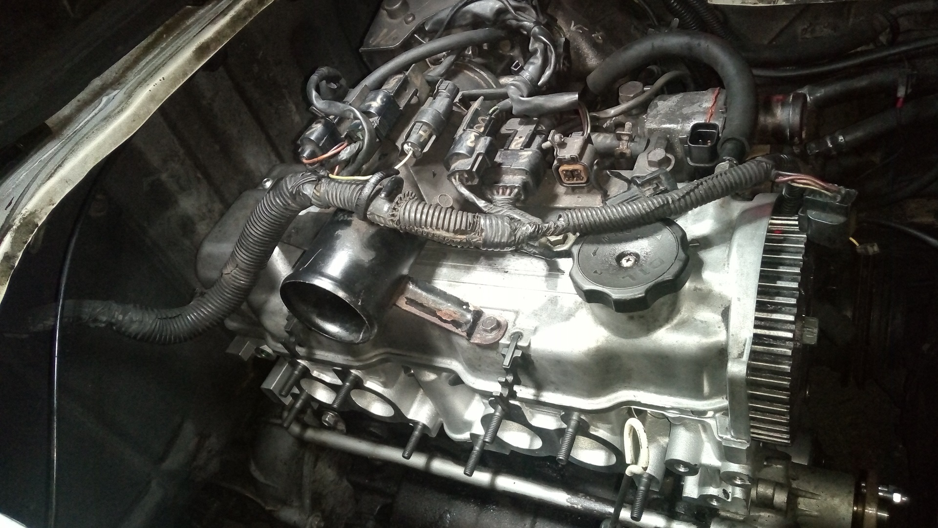
The intake manifold now being mated to the new head. I took this opportunity to replace a few of the rubber hoses which I noticed had become sufficiently mummified, including the PCV, PCV breather, and a few vacuum lines.

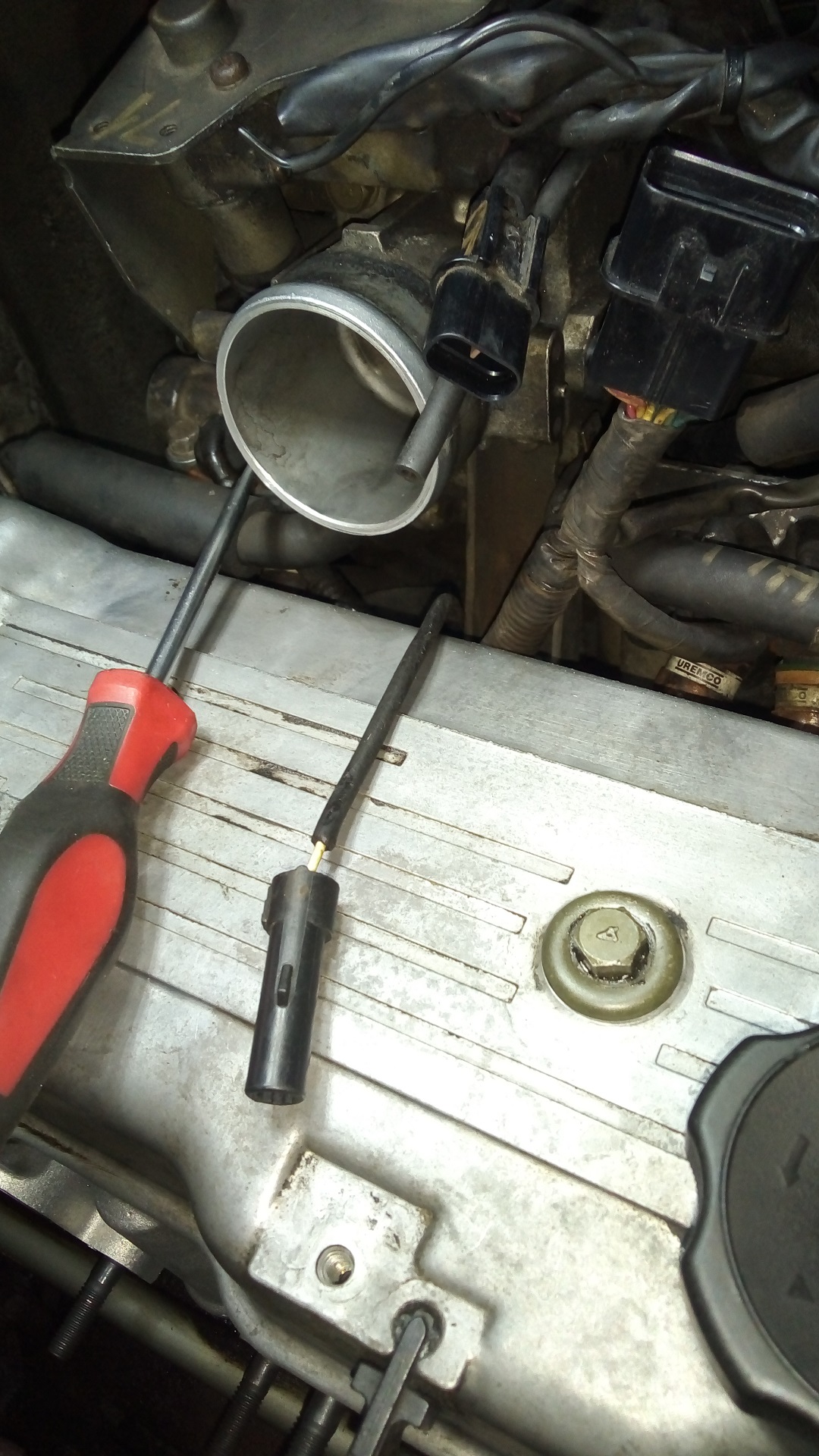
Before I go too far, just double checking that it’s correct….

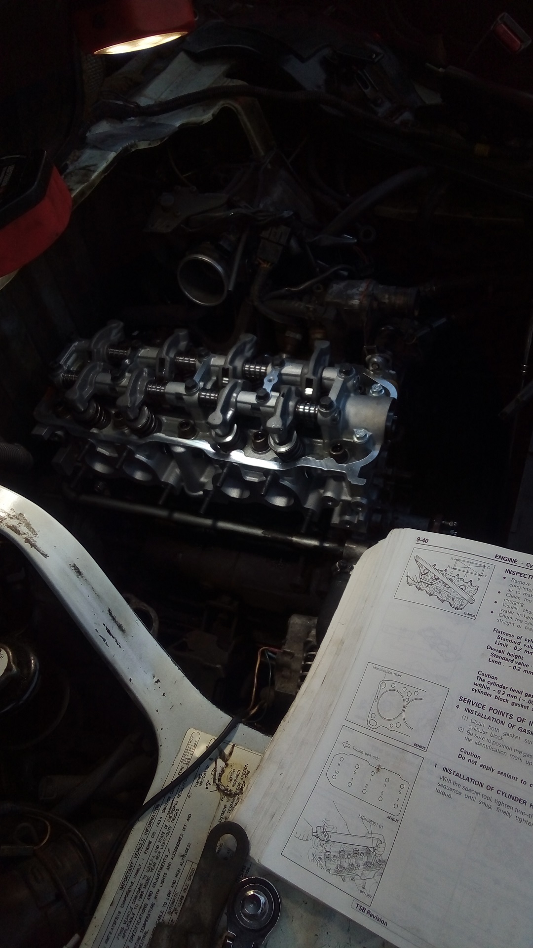
It took me a little while of searching to find how to re-mount the distributor. I couldn’t find where it was referenced in my USDM van manual at all, just occasionally sketched in with the intake manifold and cylinder head. I had to do some searching and found a 1990-1994 4G6 workshop manual hosted by the Canadian Delica club, where I found the instructions for the SOHC head, reproduced here for saving my ass later:


Hey, I have those locating features! The distributor will need to be fiddle with once mounted anyway, so I really just wanted to get the initial gear mate correct.  When it is correct, the rotor will face essentially straight downwards with the head in a normal upright position.

Now I flip it over and mount the exhaust studs, which are the same type.

After the head assembly was prepared, I cleaned and prepared the valve cover with a new gasket and also added the half-moon shaped plug to the back of the cylinder head with some silicone squirt-a-gasket compound.

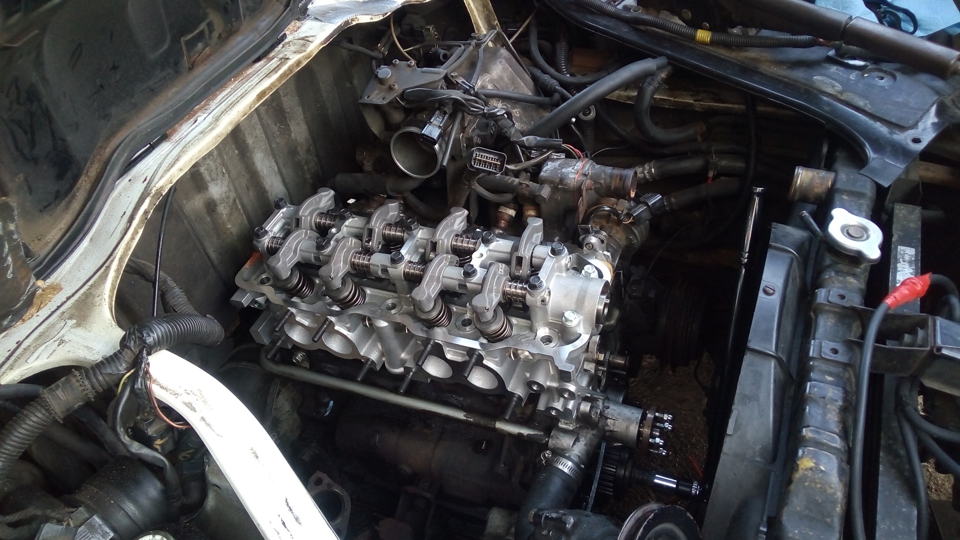
The whole assembly was maneuvered into place with some help and put in its final location without the head gasket first – this was just to make sure it was basically in the right place to begin with and we wouldn’t be hovering over a “Don’t fuck this up or it will explode instantly”-class component trying to find the two mating locations.

After it was dropped in place, I simply had someone hold the head up a little and slid the gasket into place, then the whole assembly was dropped back down. I then sprinkled some oil into the rocker and cam area, around the lifters and springs, and a bit into the valve stem seals to start them off.

The fun operation of torquing the head bolts now begins! It seems like some times you’re recommend to torque them to specification and then check it again after a few hundred miles or several cycles, and other times you’re recommended to give it some extra goose to ensure you don’t have to do that. But either way, that sounded like “old school car guy” advice…. for people who can just pop off the valve cover in their very clean and accessible open engine bays without having to remove half of the vehicle (because 50% of the length is hood) and just crank on the bolts a little harder.

You know what, I think I’ll stick with the “Extra Goosing” strategy. Beforehand, I thoroughly washed the head bolts themselves as well as made sure the clamping surfaces under the washers were clean – this was one area where I could see “Torque it a little more” being the cure-all for dirty or oily head bolt threads and lands.

With the head bolts secure, the worst of the storm is now history. Everything else from here on is making sure I don’t forget how to plug something in.

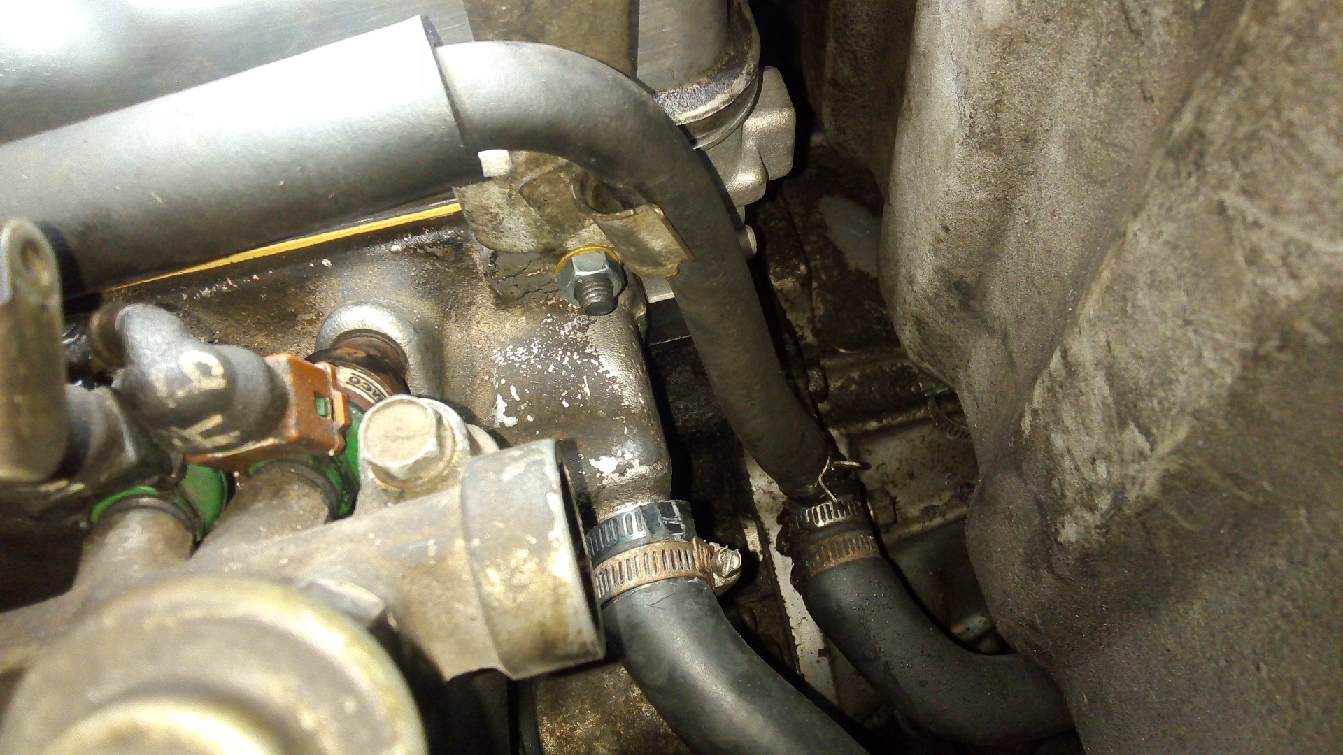
The task of reattaching all the random hoses and lines now begins. I moved all of the aft heater hose connections and clamps to more accessible positions that I could get at from the top only…… if, for instance, I had to run back in here shortly.


Some of the more snowflakey connectors had to be routed through the intake manifold curve, like the oil pressure sensor harness. They don’t reach otherwise – I contemplated extending them so they could be routed around if needed, but the idea is I shouldn’t have to keep doing this, right?

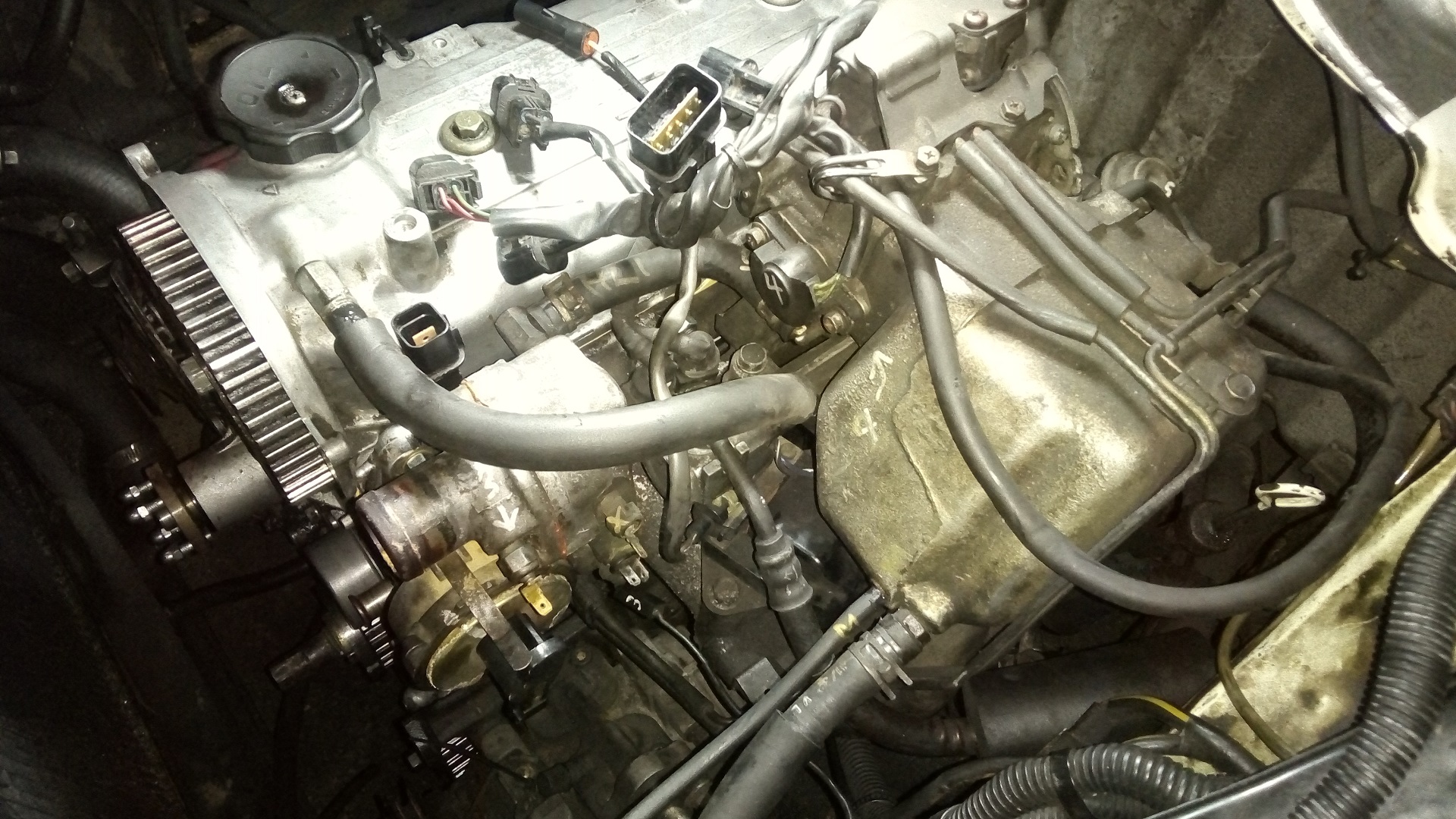
Now it’s time to try and remember what my gratuitous labelling meant. I not only drew on the connector themselves, but the connector mounts and seats, and even on the cables. And even in regions where the cables had to go. I wasn’t leaving anything up to chance.


….except, apparently, where I put two of the small M6 flanged mounting screws. What? I thought I sequestered all of the hardware in little baggies with their associated parts!

Who knows – maybe I will find these screws randomly one day in the back somewhere. In the mean time, I had to sub in two of my M6 socket cap screws.

Okay, my mechanic friends were right – things really only do go back together one way.

Making the connections on the intake side now, including several vacuum lines and water temperature sensors.


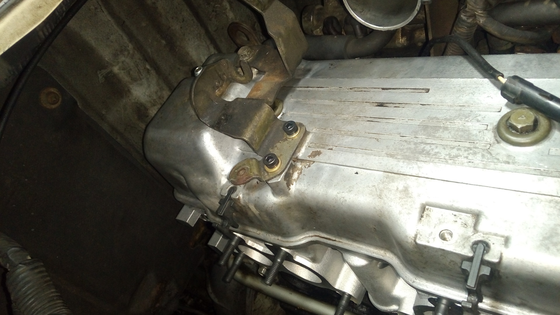
After all that was complete, I discovered what is so far the only incongruity between the original Mitsubishi head and this chinesium special: The power steering pump bracket is displaced an additional roughly 2mm in offset distance from the side of the head.

Hmm. Well, it could have been worse, I suppose. This meant the PS bracket and alternator mount don’t line up with the hole they need to. This was resolved by turning the PS bracket hole into a C-shaped slot with two quick Dremel cuts.

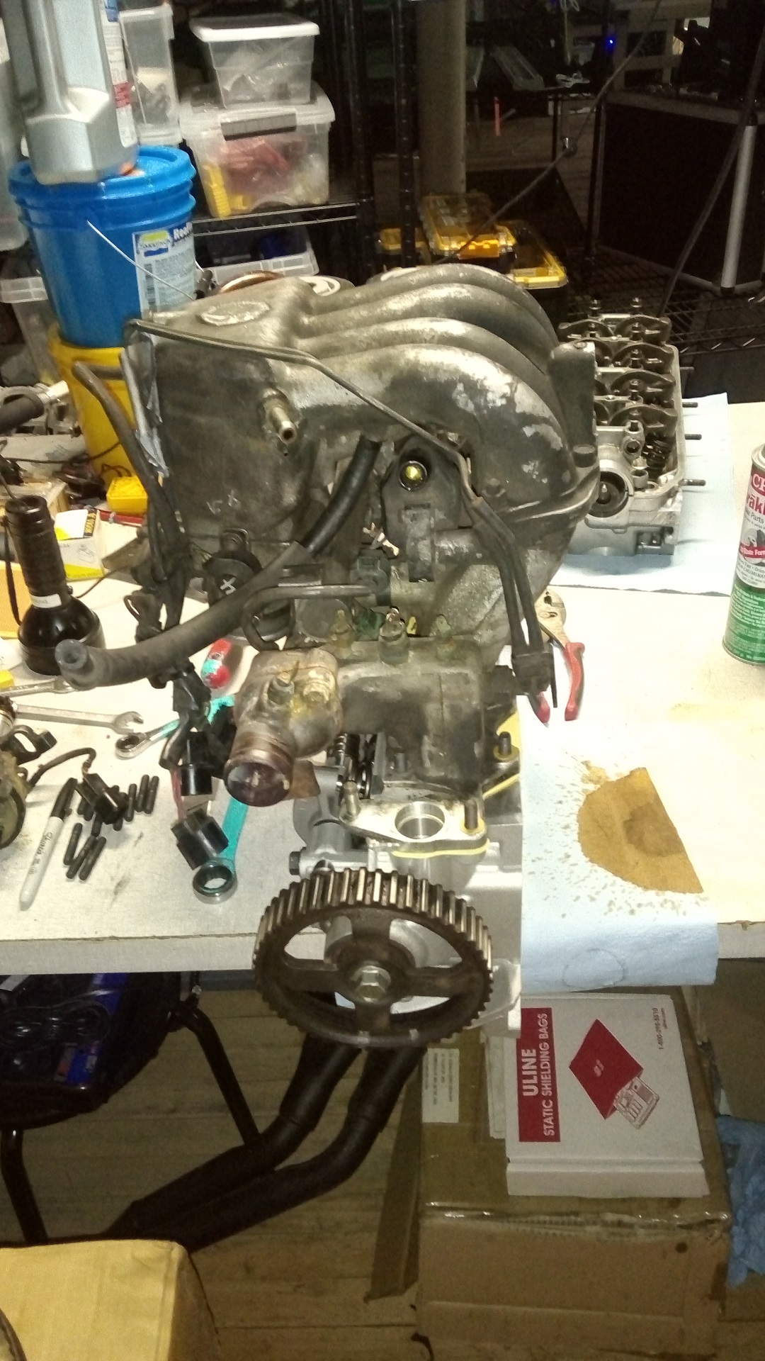
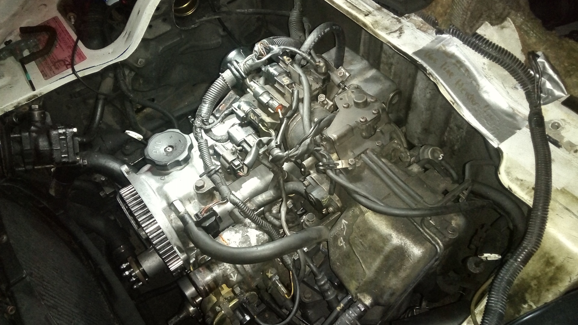
All of the accessories and cable and hose connections were now reconnected. By this time, night had fallen again, and I elected to not repeat my mistakes and try to put the timing gear back on now. That battle was for another day.

In the mean time, before I put the thing back together, I decided to tackle an additional demon:

The exhaust manifold has been cracked since time immemorial, and it’s only gotten worse over time and heat cycles. I figured while I had everything dismounted, I would try to repair the crack as much as I could. It was cracked not only through the collector region on both sides, but also in the valley, which was going to be rather hard to reach.  And honestly, it looks like several people have been here before me – as usual – so I probably can’t make it all that worse!? I picked up some nickel filler rod for the purpose after doing some research on welding and brazing cast iron.

Oh, and my new valves came in finally.


So for now, the old head also sits at the ready if it has to be recalled into service…

Operation Bad Timing II: The Soundtrack – Pistons and Valves and Seals, Oh My (God Everything Sucks)

Here we go! With the head  now off, it was time to extract the pistons and either repair or replace them while the Chinesium head was on its way. This post covers roughly the week of July 1st. The plan was to pull pistons #2, 3, and 4 out and appraise them for damage. Pistons 3 and 4 were part of the knocking-induced head gasket explosion, so they were the most suspect to me. Cylinder 2 merely showed less-than-factory compression (around 90 PSI), so I wanted to see what problems it had, and to practice my piston-replacement operations on it if need be.

The first step to being about to get to them is to remove the oil pan. Gee, this thing was stuck on a lot harder than I remember… granted, I haven’t personally opened it myself since the Great Accidental Partial Engine Rebuild ceremony, and it seems like they slathered the whole thing in silicone and slammed it on there hard. I ended up having to bend up a corner of the pan to get enough leverage to pry the rest of it off.

This corner was later hammered back into shape, but whether it’ll seal again is another question!

Ahh, we meet again. I removed the connecting rod cap of piston #2 and shoved it out the top while inspecting the crankshaft journal for any damage or abrasion.

Here’s piston #2 in all of its oil-grunged glory. I know for a fact that Mikuvan has been burning oil through the valve stem seals (at least) for the past roughly 10,000 miles, and it shows.

I decided at this point to just use all 3 of the remaining pistons in the original kit that I bought – the original piston which was replaced in the GAPER (still a very unfortunate acronym) was #3, which was one of the now-untrusted ones. Since #1 showed nearly factory compression, I was just going to leave it alone.

This meant making….

Big Chuck’s Automotive Special Tool #BCA-9001-3939-A, Mikuvan Piston Pusher. The factory manual showed an object not unlike this, which led me to conclude it was just two tubes. Well guess what, I also have two tubes and a hydraulic press. The larger tube is a 1.25″ OD thick-wall tube, whose bore I enlarged to 15/16″ to clear the 22mm piston rod, and with two notches machined out to accommodate the piston’s flat face. The tube was in fact originally bought for either creating the hubs of Chibikart or Chibi-Mikuvan’s steering uprights.

It was then easy to push the piston pin out and free it up. Part of my rage-ordering of every component I might need was a new set of crank and connecting rod bearings, and I decided to just go ahead and put them on anyway because why not, I already had this stuff out.

Essentially I was working with the assumption that everything which has touched a pre-ignition event is immediately suspect out to like 2 layers of the network away. In a way, it’s like how I repair my motor controllers: if one FET lets go, its friend on the same half-bridge is replaced, the gate driver is replaced, and all power supply components that are semiconductors nearby are replaced; after all, if you already are heating up the board for reflow, you MIGHT AS WELL.

With my post-facto knowledge, I now understand that this is a better assumption for higher-strung newer engines, or ones built for high performance and racing, in which the stakes are much higher if something goes wrong. Mikuvan’s engine is rather the opposite, an understressed low-revving truck engine which only ever made 107HP out of 2.4 liters new and had an incredible 8.5:1 compression.

My adventures consulting my vanstylists, “car guy” friends, and the Internet at large including Mitsubishi Delica owner forums/groups and reading in general about engine explosion scenarios, has forced me to conclude this: All Internet car advice is horrible and irrelevant.

You need to decide what is best for your application by Kalman filtering your own experiences in with all the differing advice you’ll get, mostly from “car guys” who insist that things must be done a specific way or it’s not worth doing at all.

I luckily have the upside of having a lot of mechanical system intuition that made me question “car guy” advice – do I REEEEEEEALLY need this? Is this the ONLY way things happen? Maybe if I actually did have the turbo Evo engine… And then some from my trusted mechanics who have in the past advised me on what I could conceivably get away with versus what would fail right away, which I was more trying to gauge. I know I’m not doing anything truly correctly, so how topologically-correct can I remain?

Anyways, in conclusion, I could have probably run Piston #2 just fine after replacing the rings, but again, Might as Well if I have the parts handy. So on a new piston and rings go. I learned a great deal about the neckeardry that goes into piston rings doing research on them; these are one of the Insta-Fail scenarios, if you put in the rings upside down or inside-out, they will not seal properly or prevent oil burning. If you don’t install them in a certain rotation (phasing, clocking) according to the factory manual, you could get compression issues right away and uneven wear in the cylinder long term.

There are just so many small details to get “right” that all affect long term operation, yet are presented to you as life-or-death scenarios, which you have to distill out for applicability.

I suppose the advice is all bent towards people who would rather not jiggle with their engine internals on a regular basis.  But hey you know what an electric motor is? It’s one round thing that spins inside of another round thing. I heard the kids are into them these days.

My “car guy” friends absolutely begged me to hone the cylinder bores before installing the pistons again. Another one of my mulling conclusions is that everyone seems to think Mikuvan is more fucked than it actually is, with talks of cylinder wall scoring damage as if I ran the thing without oil up a mountain.

I do rather think the cylinder walls were all fine, but again doing my Kalman Filter research it seems like putting in new piston rings on a previously worn-in surface wouldn’t do me much good in the long run, and buying a simple flexible hone and sticking it on a drill is not hard. So that’s what I did!

I alternated pushing the hone with spraying the area down with WD-40 (you’re apparently supposed to use a dedicated honing oil for Best Results™) while the crankshaft below was covered by a few shop towels to prevent the metal particles and abrasive dust from falling on the journals. I cleaned the journals afterwards with some brake cleaner regardless.

Using “Irritating 1-purpose dedicated automotive tool #21892”, a piston ring compressor, I loaded the new #2 piston in with a healthy dousing of motor oil (you’re supposed to use dedicated assembly oil for  Best Results™). There are SO. MANY. stupid irritating one-purpose tools to do things expediently.

I have to wonder if all this is just entrenched through generations of automotive engineering and service or if there is an actual reason there’s a squiggley-shaped object called a Distributor Hold-Down Wrench. Boy that would have sure saved me a lot of time when I was dismantling most of vantruck’s accessory belt drives off to assembly a specific order of socket universal joints and extensions to loosen its distributor hold-down bolt.

And here I thought the world of drones and 3D printers were a horrifying mess of tribal knowledge – I clearly have never actually worked on cars up until this point. That is a hundred and twenty years of tribal knowledge.

After feeling pretty good about piston 2, it was time to do the same thing to #3 and #4. I was expecting more gore here for sure.

Here they are extracted. #3 on the right was replaced during the GAPER, but it and #4 show some pretty serious signs of oil burning.

They also both had stuck piston rings, #4 moreso than #3. Grunge filled nearly the entire volume of the oil control rings, which were probably doing dubious controlling at this point. So something was bound to fail sooner or later. The further back in the engine, the more it butts up against the firewall (which is actually behind me) and presumably the hotter they get. I’d like to think this is why cylinder #1 has barely shown any problems – it’s first in line to get water, cooling air, and oil pressure.

Control-C Control-V the whole procedure – cylinder honing and cleaning, piston swap, rings, and bearings… to pistons 3 and 4 and back in they go. I figured I did it mostly right if it still turned by breaker bar as easily as it used to.

For now, I put a few towels over the whole thing and went back inside to inspect and work on the cylinder head itself.

The intake manifold is seperated from the head by a few mix-and-match nuts and bolts. This was a little weird to me, since I was expecting all studs and nuts versus half of them being hex-head screws – maybe that was factory, or maybe someone’s been in here before.

Nevertheless, this was when I discovered that this thing DOES have an EGR system. As I mentioned before, the EGR valve was always drawn in isolation with little context of where it actually was. By my guess, I thought it sat behind the cylinder head, and when I didn’t feel it there, I assumed that it was a CA-spec emissions versus REAL AMERICA spec difference. It turns out the damn thing is nested in the U-turn that the intake runners make from the throttle body. The small center tube between the four larger intake runners is the EGR passage, and it mates up with a similar passage which dives through the head and pops out near exhaust valve #4.

What?! Well, either way, this passage was very clogged – not all the way closed, but significantly. Given that I’d never had any EGR-associated idling problems, I decided to leave it alone – I just filled the whole cavity with brake cleaner and came back a few hours later to blow it out with shop air, whatever I could get was it!

The cylinder head itself was fairly caked with oil grunge, with cylinders 3 and 4 being the worst as expected.

My goal with this head was to replace the front oil seal, the eight hydraulic valve lifters (the round bumpies poking out of the upside-down camshaft on the top left), and the eight valve stem seams, which cause the oil burning and vape cloud on startup behavior. While I had the valves dismantled, I was just going to casually clean them and the chambers they sit in – casually meaning yes, I know I’m supposed to take everything off and chuck this thing in some ultrasonic cleaner filled with teratogens, but I think the application is not strenuous enough to warrant it.

This…. is where I got to use “Irritating 1-purpose dedicated automotive tool #37985”, a valve spring compressor. It also ranks as the most terrifying tool I’ve used yet, since it’s literally stamped sheet metal holding onto an angry die spring, and that’s supposed to be an okay thing. I’ve witnessed a suspension spring/strut compressor tool being used before. That is something I will never voluntarily stand next to if I can help it.

It turns out all that holds the valve springs on are these two little taper-lock bushings, literally called “valve spring retainer locks” and similar. I’m frankly amazed they don’t just shear off all the time. Once you compress the valve spring, you bean it downwards to unseat the taper lock, upon which these little halves fall out. Whatever, I’ve already suspended my belief that combustion engines are actually things that work okay for long enough, let’s continue!


Yes, the valve stem seams were all very crispy. On the left, a new one. On the right, the hardened and bloated lump that was in it. Sure as hell not doing any sealing, as all of the valves came out with very oil-covered stems and backsides.

I’d also noticed some mild leaks on the camshaft, which is explained by its own hard-as-a-rock seal on the right.

In dismantling and cleaning the valves – mostly wire brushing with some brake cleaner love – I found the reason for cylinder #2 showing slightly low compression: I had a cracked exhaust valve. Very unfortunate, as this means I can no longer just put this head back together. I immediately jumped on eBay and searched down some new-old-stock valves. No matter what, it means a delay in putting things back together.

I was otherwise going to replace ONLY this exhaust valve – I figure all the other ones have already met their own valve seats for a long time, and redoing all 8 would involve having to clean and re-grind the valve seats also. By this point, too, I was also getting tired of the dozens of minute small manufacturing processes that all have to be done and special tools that have to be used, to make things work “correctly” – I wasn’t planning on performing the valve seat grinding/polishing operation at all on the replacement exhaust valve either, just a quick cleanup of the existing valve seat and making them be friends by thermo-mechanical coercion.

Natural technological progression is really an evolutionary process unto itself – you end up with systems that have thousands of micro-optimizations in different places for different things, instead of clean-sheet designing something with the knowledge of the system you now have. That takes a lot of time and money, I suppose. Having researched obsolete combustion engine technologies in the past, it makes me wonder if one or the other design was just invented at a bad time when metallurgy and manufacturing couldn’t support it existing yet and they really were fundamentally better concepts which could do away with much of the “every page in the engineering textbook” experience so far.

It also made me appreciate, and maybe mildly envy, the people who got their engineering career starts working on vehicles, the “car guy” friend in high school everyone probably had, including me. Frustrating folk knowledge aside, you really do get a sampling of every engineering industry in making a working automobile, a huge head start on the pratical side of things. I like to think I gained some of this edge by working on my robots and silly e-vehicles, which perhaps lends me to criticizing the combustion engine industrial complex now.

Waiting on the valves meant I put a temporary stop to work on this head for a little while, enough that on the following Monday morning, I awoke to a pleasant gift from the Chinesium Fairy….

Well, it’s cylinder head shaped, so we’re off to a good start. Stay tuned for more!!?