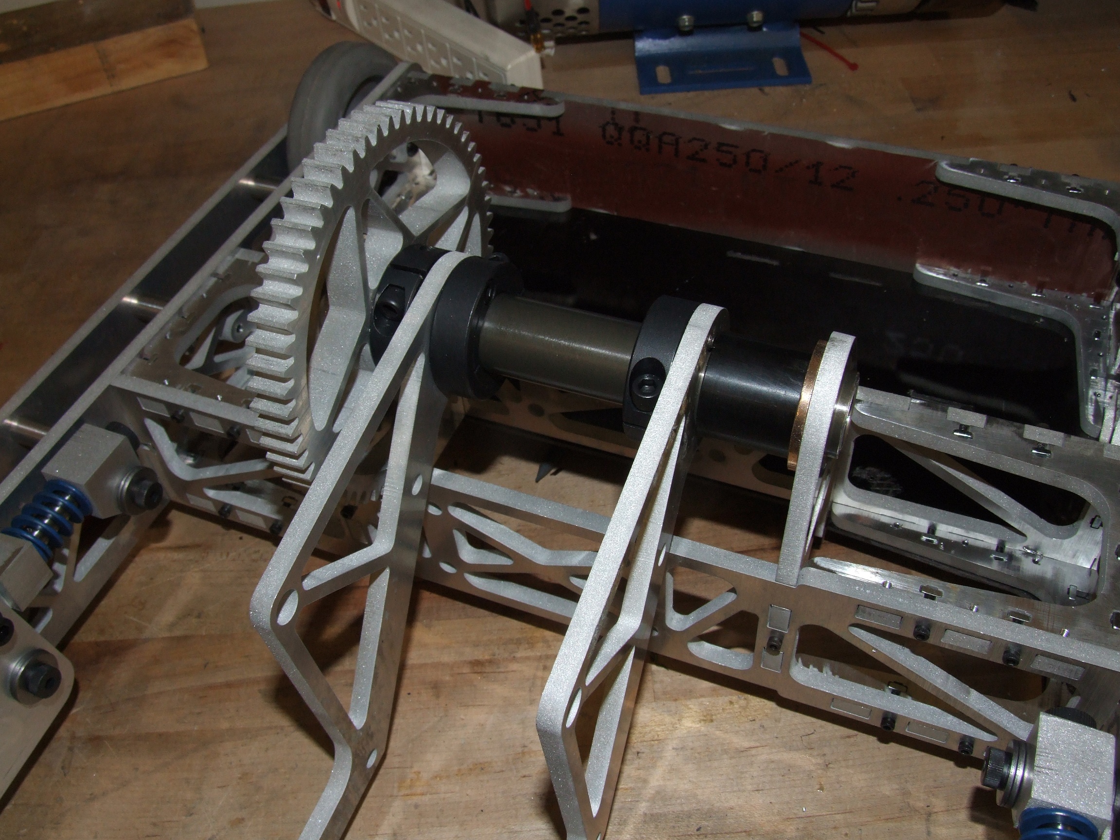
Continuing on yesterday’s update, here’s the tale of wiring Clocker up over the past two days, plus (finally!) some video of driving and testing. As of right now, I’m pretty much ready to call the bot “done”. As in, maybe not everything is perfect yet, and perhaps not everything has been tested to breaking… but if Motorama were in fact tomorrow, I’d be comfortable with pitching it into the arena.
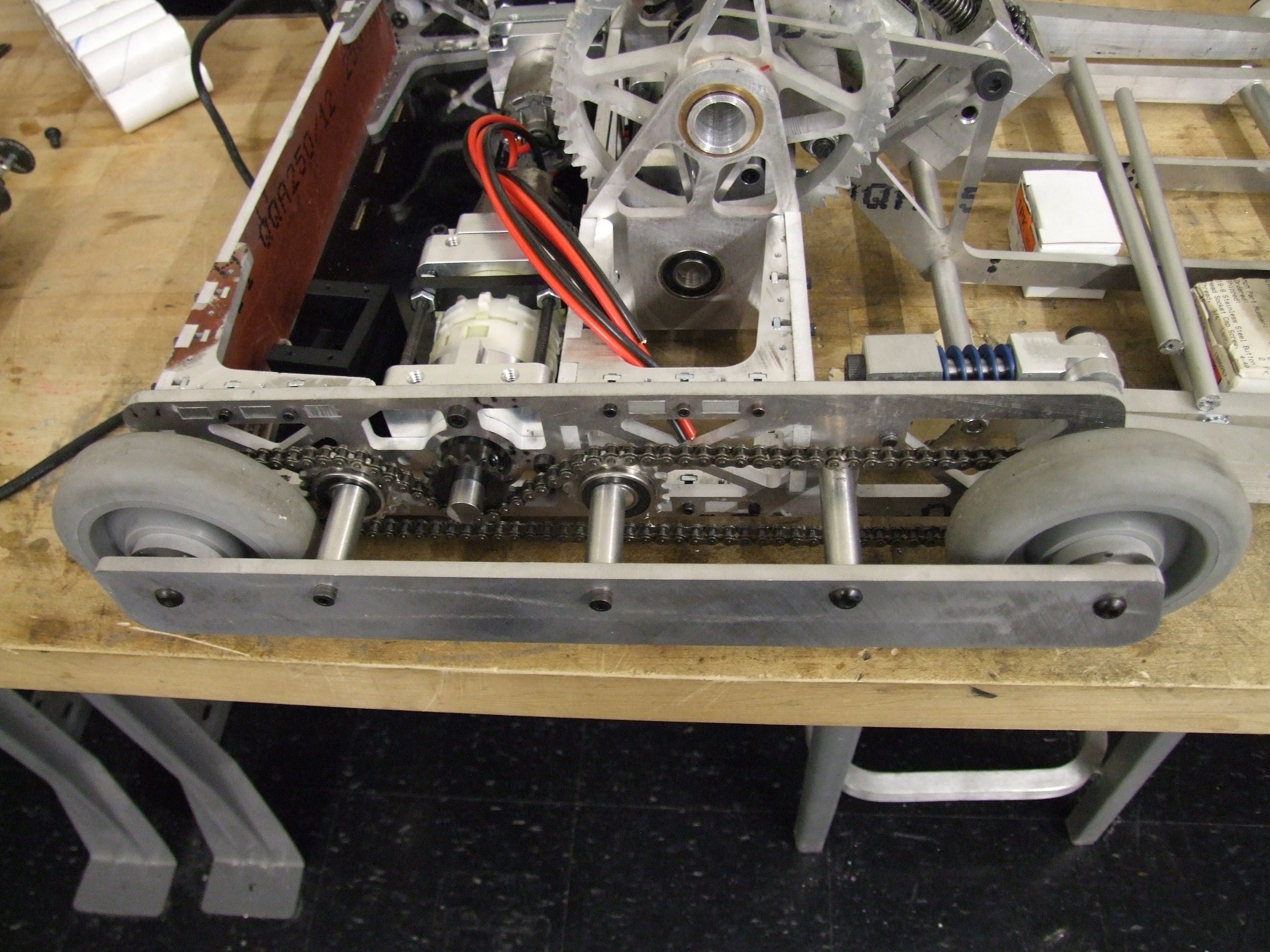
With the bot basically having reached mechanical completion with the routing of the drive chains, I turned my attention to the wiring end of things. Clocker uses two RageBridges (And So Can You!), one for the two drive channels and the other for the clamp and fork.
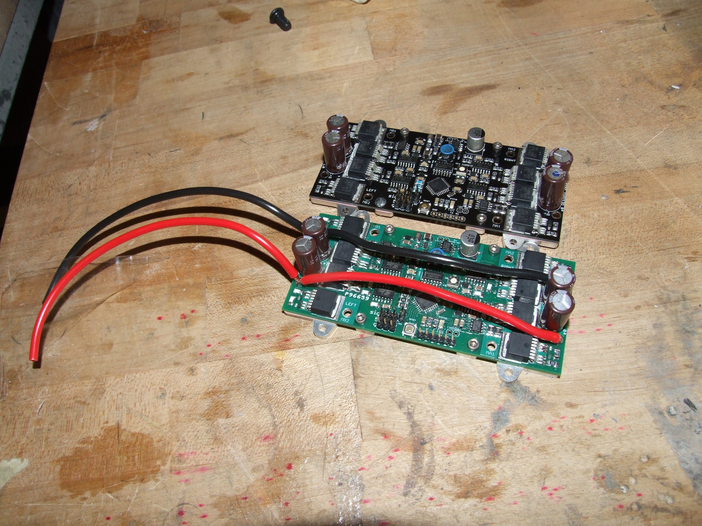
In the past, I’ve bussed together the two power inputs of RB on the bottom, but since now I’m working with the boards with heat sinks, this is no longer possible. Solution? Just bus across the top. Now, “production” RBs are supplied with 4 battery wires, but this is one way to cheat a bit and get a one-input system. Yes, I know this layout is terrible.
The green board is actually one of the revision 5 prototypes which are functionally identical to the production boards – I didn’t want to consume a production board which could be sold for my own giggles if I had workable prototype ones.

Next up was making the power source of the whole bot. Originally, I was planning on an 8S2P configuration using A123 cells. However, actually assembling 16 cells together and trying to stuff them into the rear cavity with a RageBridge made me realize that it was just utterly impractical. The fit was extremely tight in CAD, and the CAD model does not include the many layers of shock absorbing rubber foam and heat shrink I coat these things with.
So I dropped to 7S. No matter – that just means Clocker goes about 17mph instead of 20! Big deal, in a 24 foot Motorama arena or a ~12-18 foot Dragon*Con stage!
This is a picture of the pack in progress. I used my usual construction technique of copper braid and split balance harness (so my fairly average hobby-grade charger can actually recognize it).
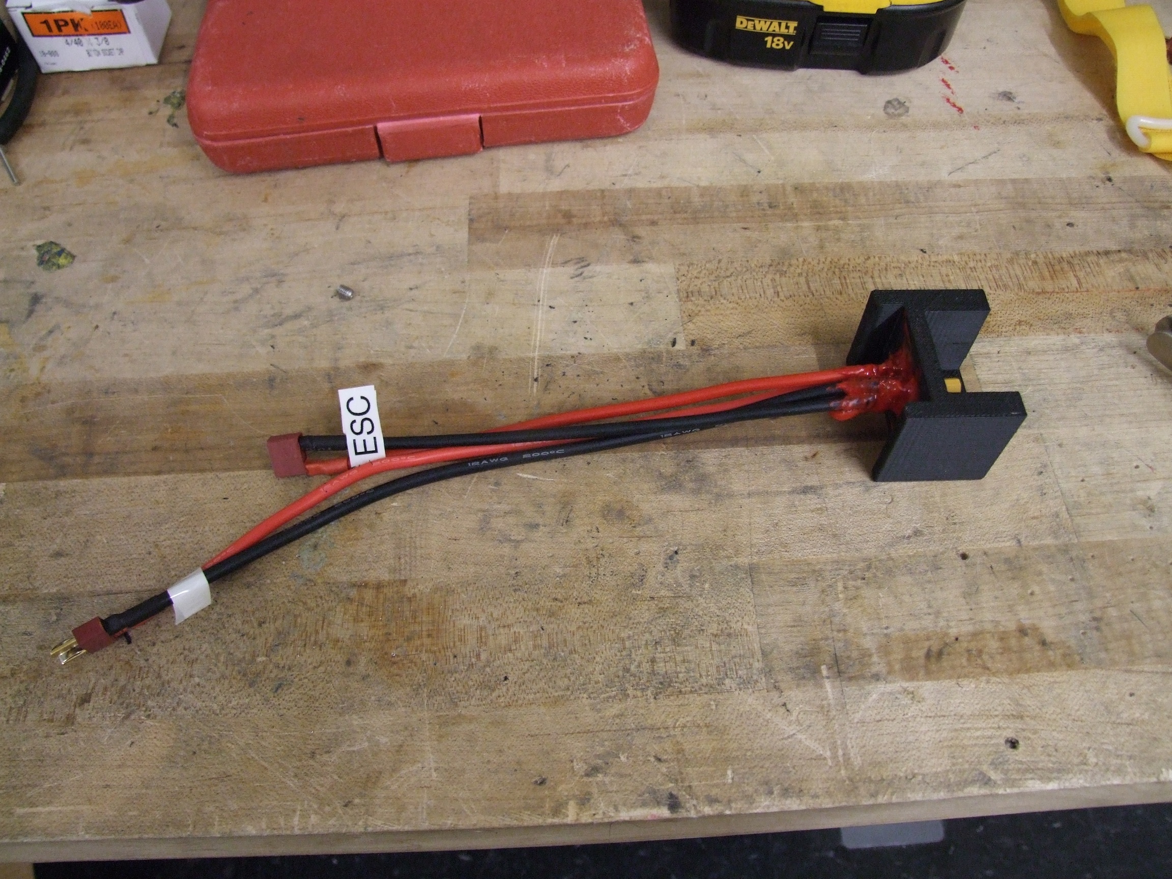
Like Null Hypothesis, I’m giving Clocker an integrated charge and switch port. There’s a Deans connection which is really just a removable link, then an XT-60 type connector which has a direct battery connection. Why do I make them different? Because otherwise you risk dropping that removable, super low resistance link right across the battery. Yum…
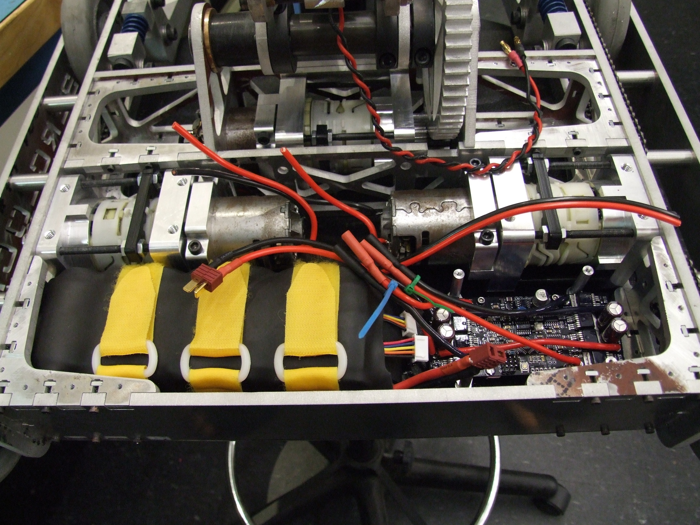
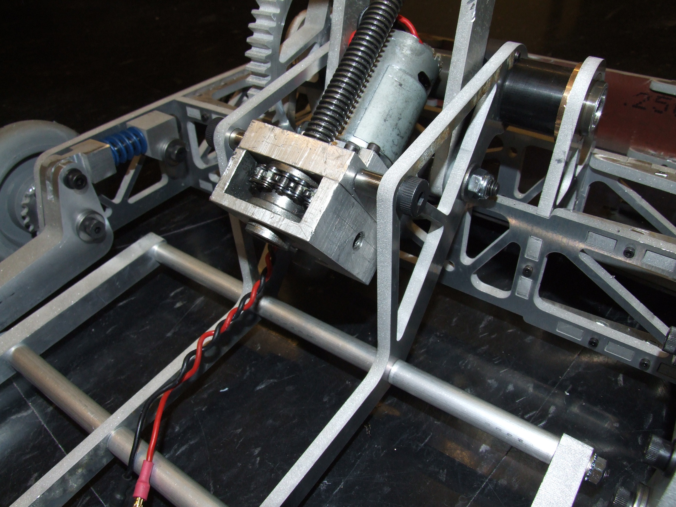
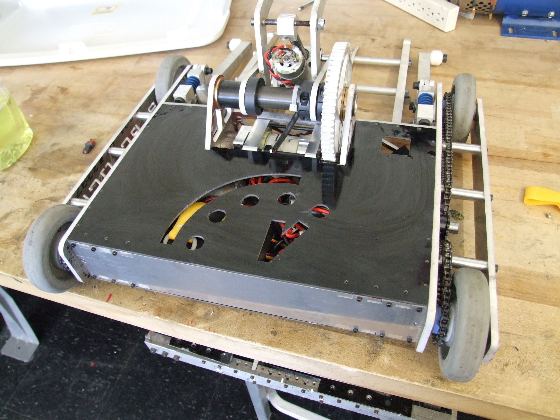
To test the drive, I mounted 1 RB and the battery in the rear of the bot. The “production” RB was used because it has heavier traces than the prototype and the drive motors will be stressed much more, current-wise. With only the drive hooked up, I took the bot for a spin around the hallway.
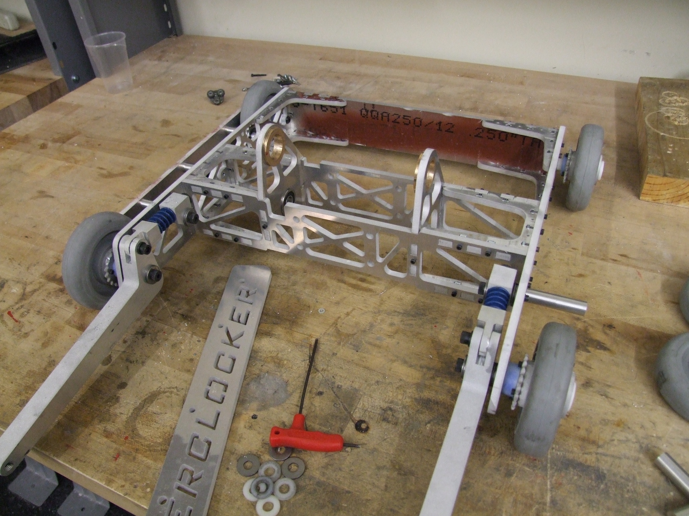
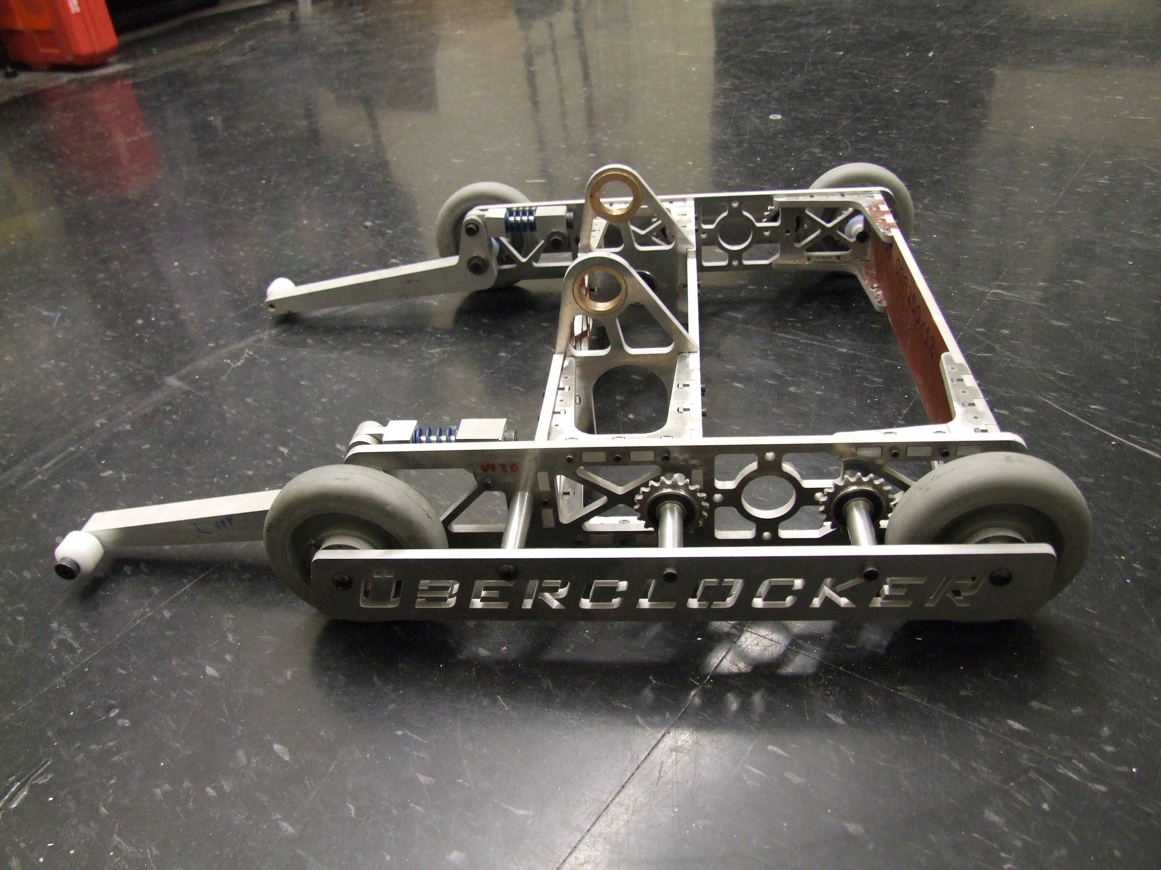
I’m very satisfied with the drivetrain. Unlike Clocker Remix and Clocker version 1 in 2008, there was no attempt to keep the center of gravity as far back as possible. Rather, it’s near the centroid of the wheelbase and track rectangle. Result? This thing handles so smoothly – almost as good as Null Hypothesis, which still wins just because it has fatter wheels – Clocker tends to drift and slide. Previously, Clocker had a particularly nasty oversteer issue because the weight was purposefully far back, causing uneven wheel dominance in turning.
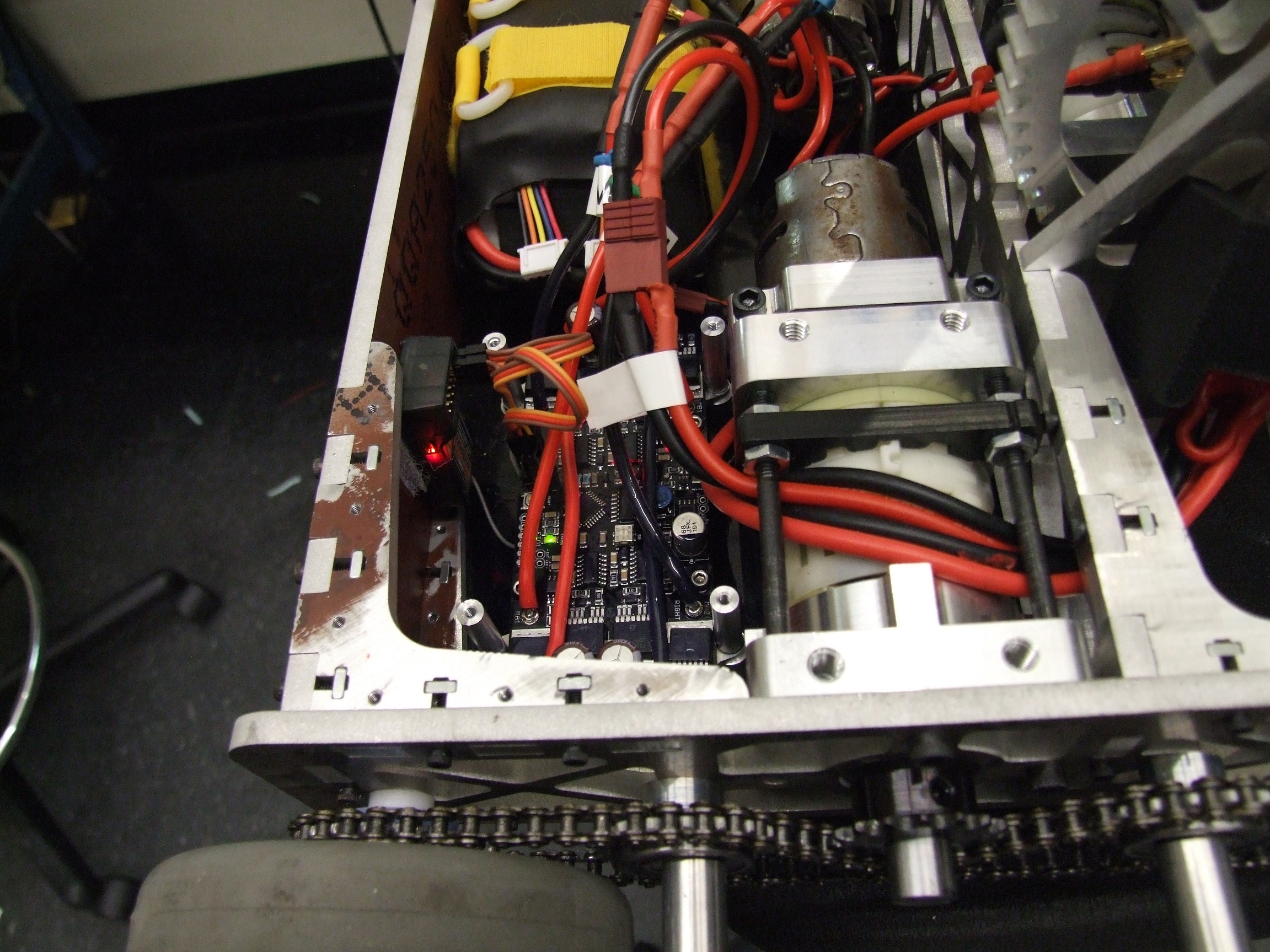
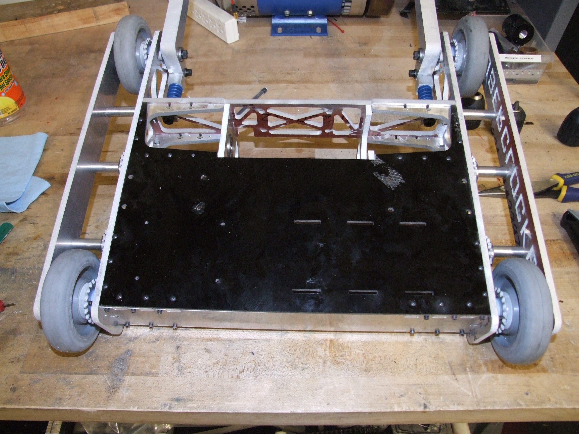
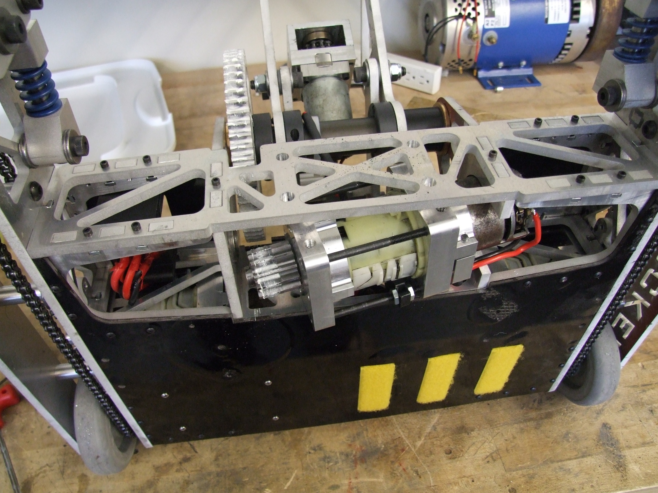
A better shot of the controller installed in the bot. It’s actually raised off the bottom plate by 1/4″ spacers. The threaded standoffs act as nuts to secure the board against those spacers, and then the fork/clamp controller sits on those threaded holes. The receiver is stuffed right next to everything by the back.
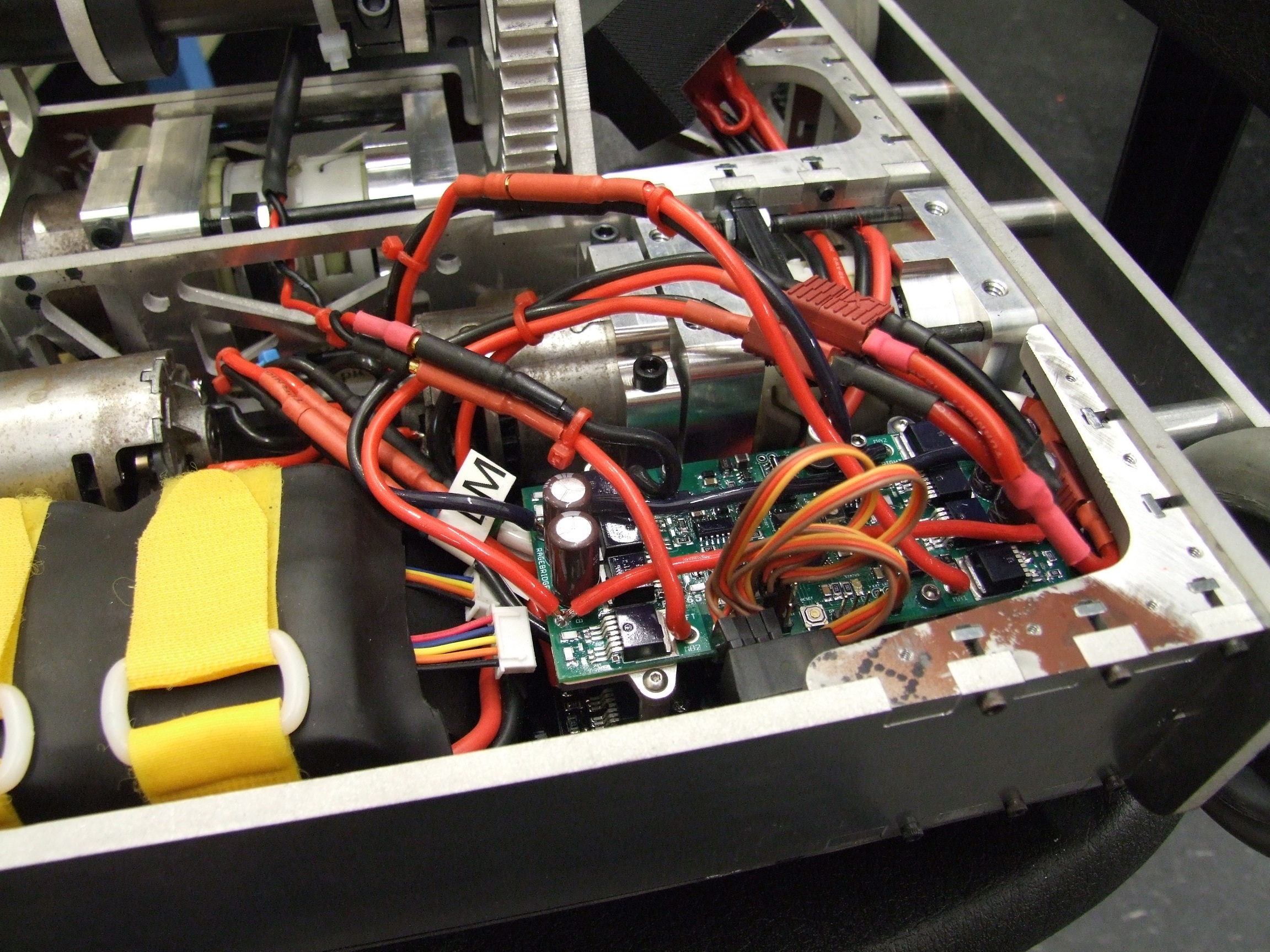
And the ‘upper deck’ in the Tower of Rage is assembled.
The top plate needed a bit of filing, sanding the edges, and enlargening the waterjet-cut pilot holes to slip into place. It’s retained by the same #4-40 button head screws that I normally hate so much, but hate #6-32 even worse, think #8s are worthless, and consider #10s too big for the job. So… yeah.
With all of the electronics and pretty much all the screws in, I took the bot for its first moment of truth: the weigh-in.
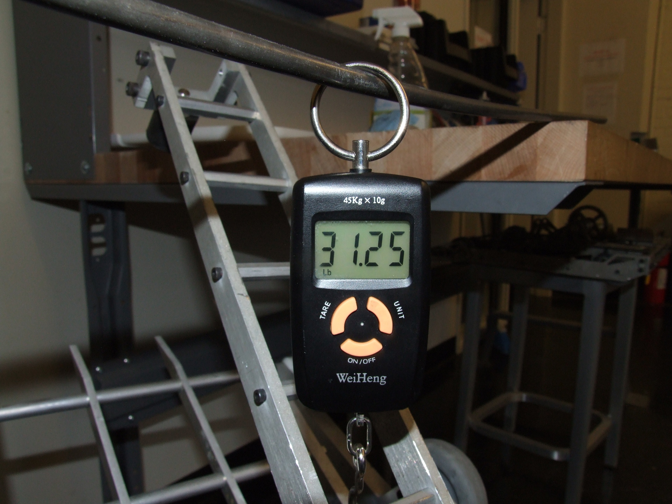
Uhhhh… well that isn’t good.
Now, what on earth could I have missed? The CAD model included almost all screws and the full 8S2P a123 pack and still came in at 28.5 pounds! I’m going to just assume that things weigh more than what I could have guessed – for instance, the threaded rods binding the fork together weren’t modeled, which seems silly since they’re quite huge. Additionally, the top and bottom plates were modeled as phenolic material when they are actually fiberglass (garolite G-10). The difference in that alone turned out to be almost 0.2 pounds per plate!
Well then. Clocker has to ditch 1.25 pounds somehow.
I spent a while thinking about possible plans of escape. I had very little metal that I was comfortable with “speed holing” since it would compromise the somewhat complete armored perimeter of the bot.
Replacing said top plates with polycarbonate would save about 0.35 pounds per plate, but I did not have the material on hand at the moment, and it wasn’t enough by itself.
Dropping to 6S on the battery would only save a few ounces, and I’d have to tear the battery apart again. The final solution had to involve multiple changes.
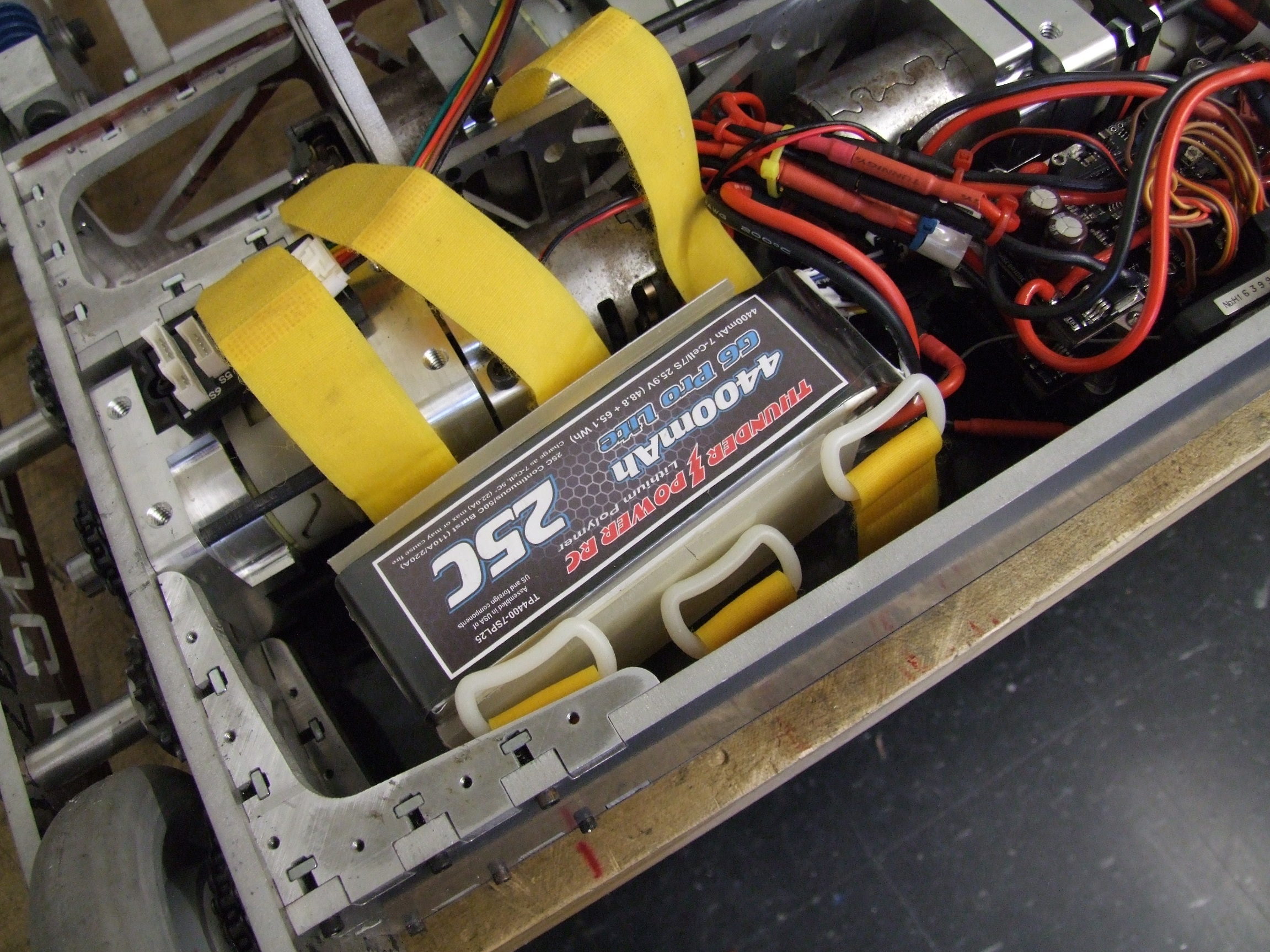
With the heaviest of hearts, I grabbed one of the left over 7S 4.4Ah Thunder Power lithium polymer packs from the amphibious DERPA project team and replaced the A123 pack. Sadly, no matter how much I love the little white round cells, the lithium pack just has greater gravimetric energy density. I gain back what is essentially an 8S a123 voltage (25.9v nominal), with essentially the same capacity. And, it saves 0.75 pounds; even with the two G-10 plates I added to the top and bottom to make the pack simulate a hardcase battery so it isn’t as squishy.
Now, with Clocker at 30.5 pounds, knocking the rest out of metal was a possible course of action.
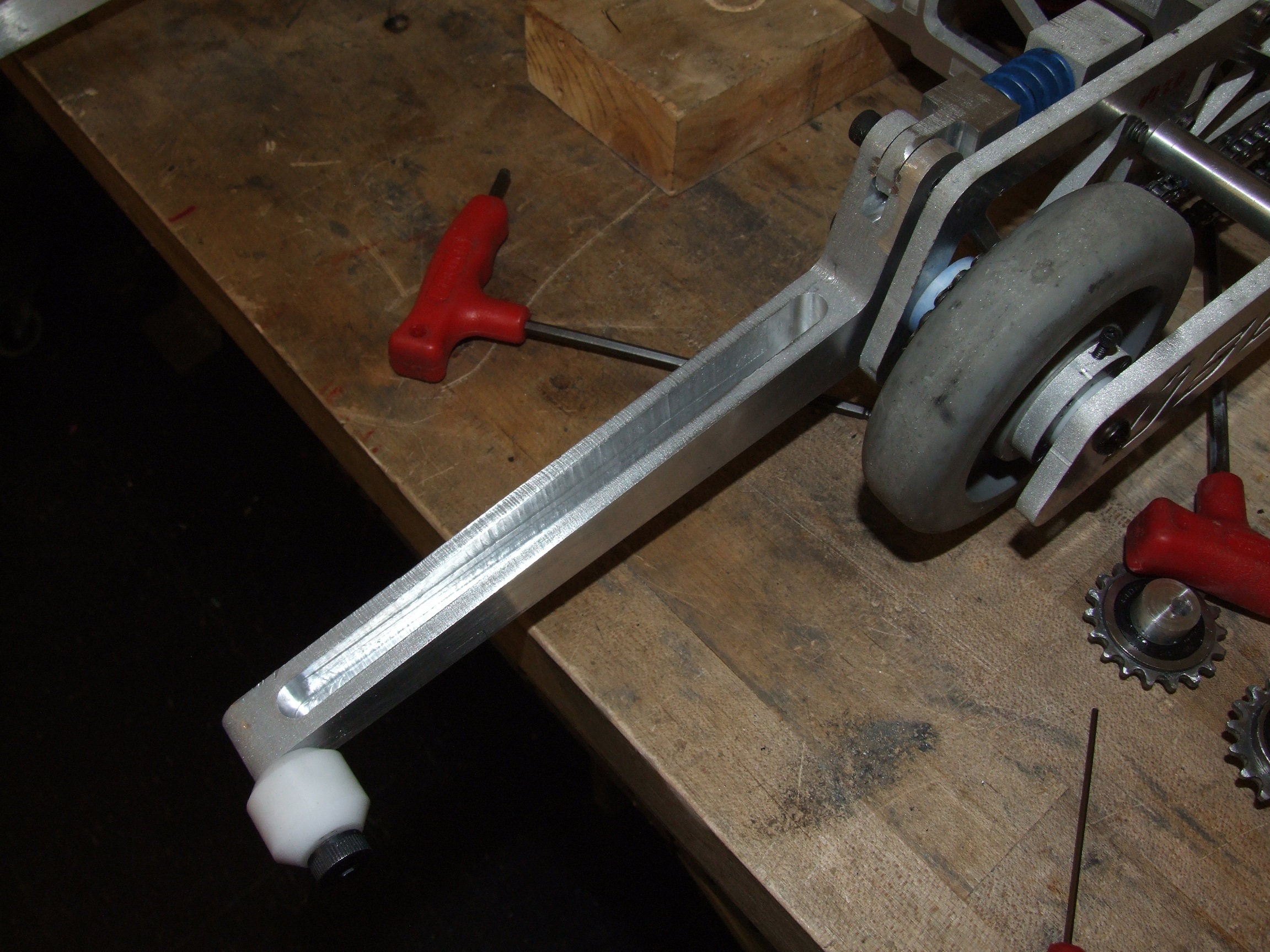
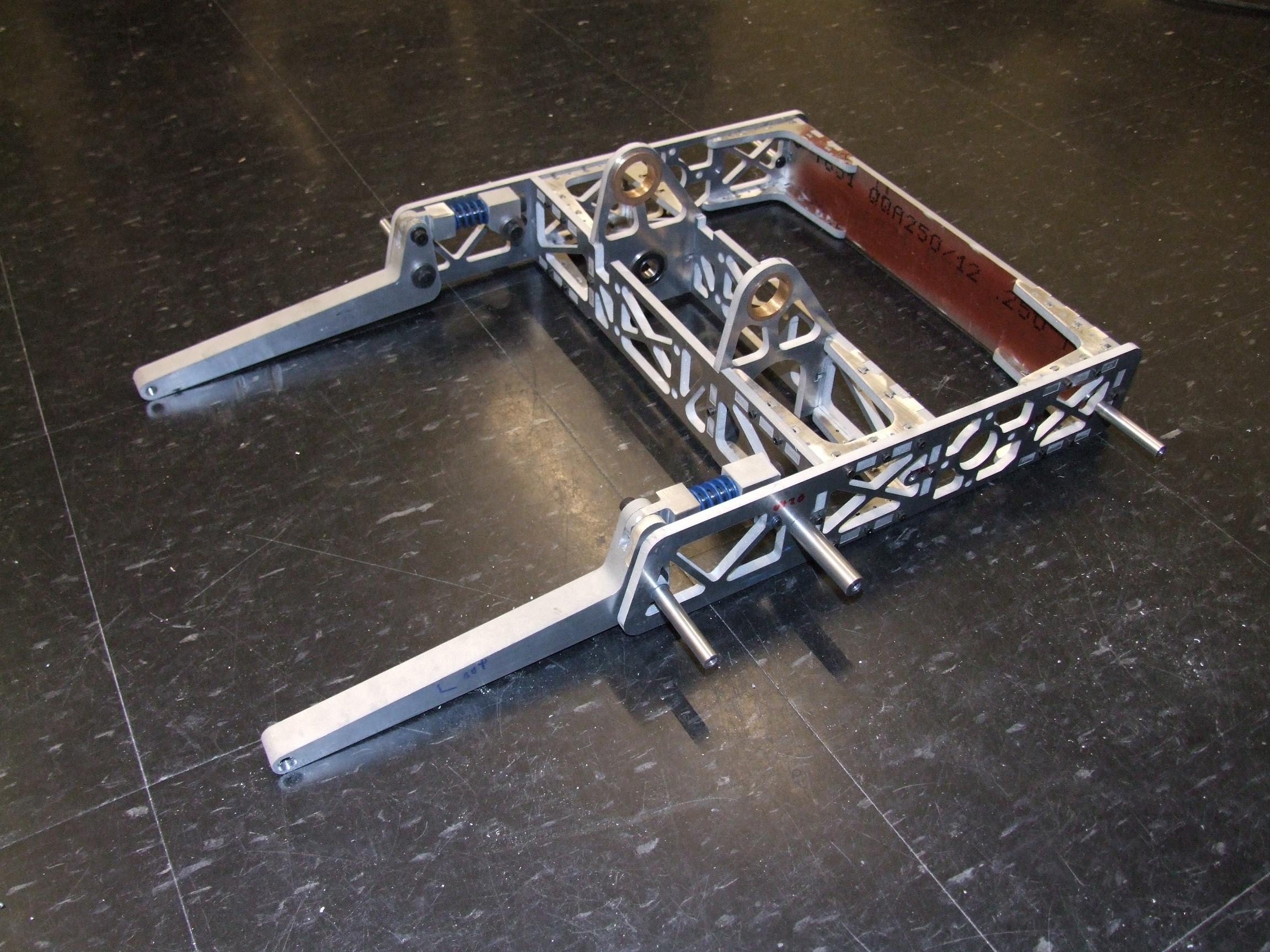
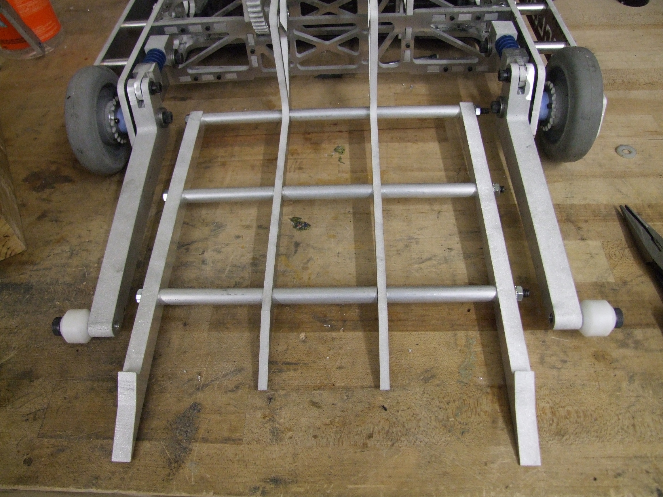
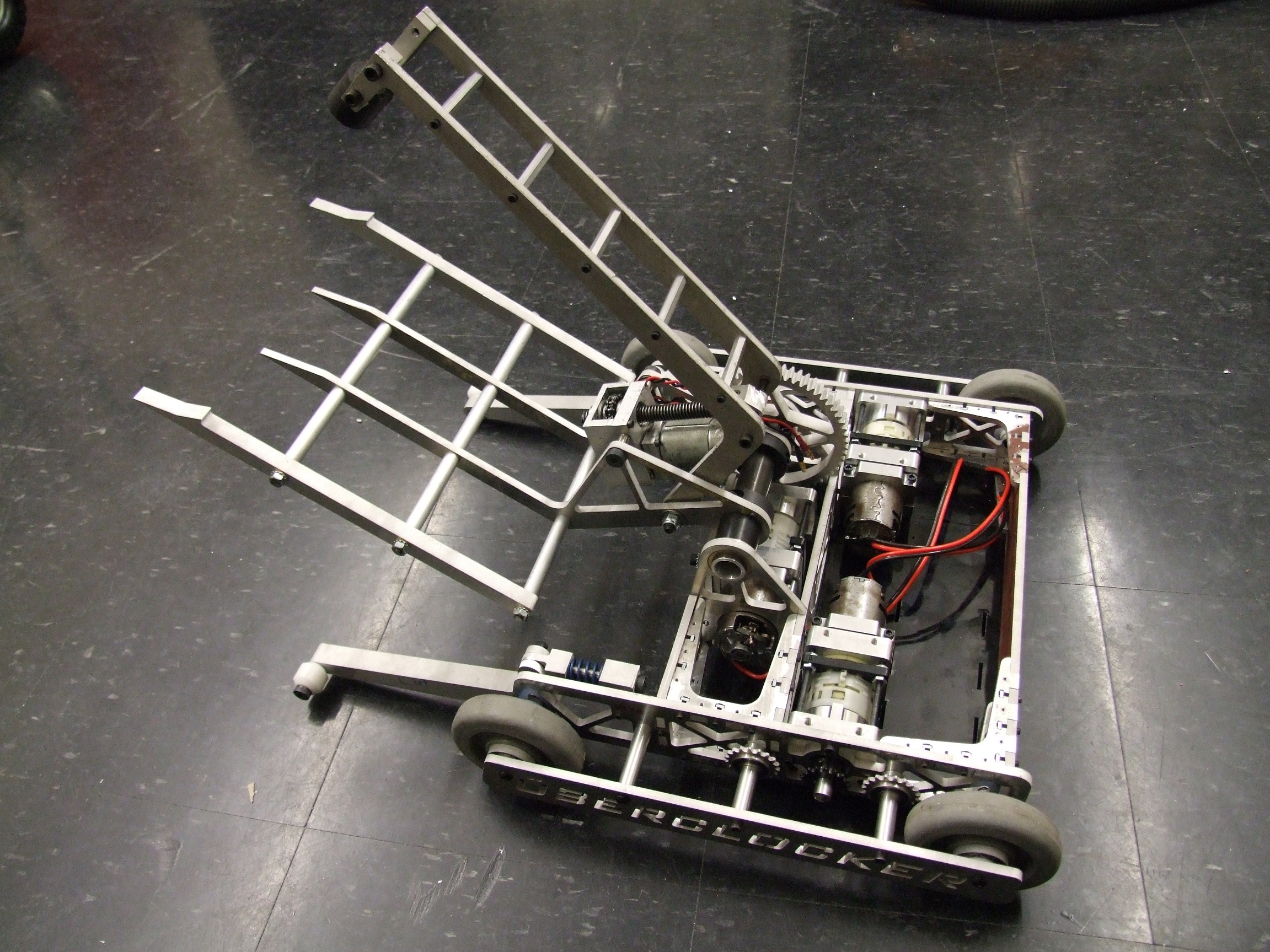
I always figured I was going to have to machine out these landing legs eventually. They’re solid 3/4″ aluminum. That’s almost obscene. Each slot basically netted me 0.14 pounds, so a cool quarter pound for the pair.
There’s a quarter left, still.
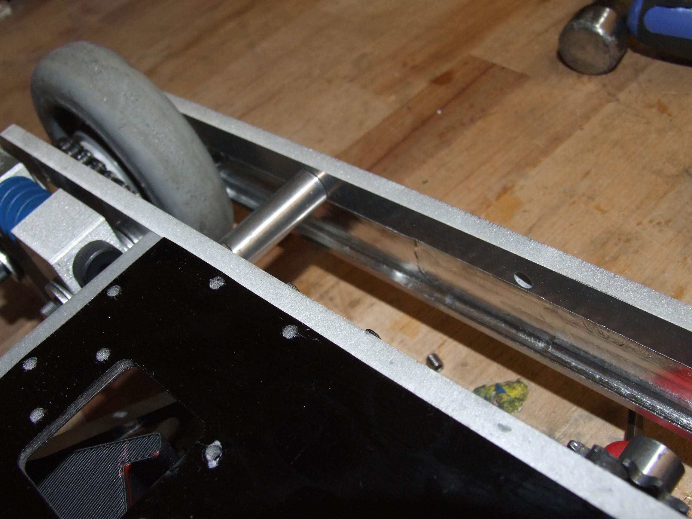
The rest of the quarter came out of the right side outer frame rail, which was solid 1/4″ aluminum. I hollowed it out to a wall thickness of 0.1″ on the outside, and this was able to knock out just under 1/4 pound. Since the Sportsman’s Class does not have to contend with heavy hitting cheap shot kinetic weapons, I was completely fine with this relatively thin (for a combat bot, anyway) side armor.
The final result?
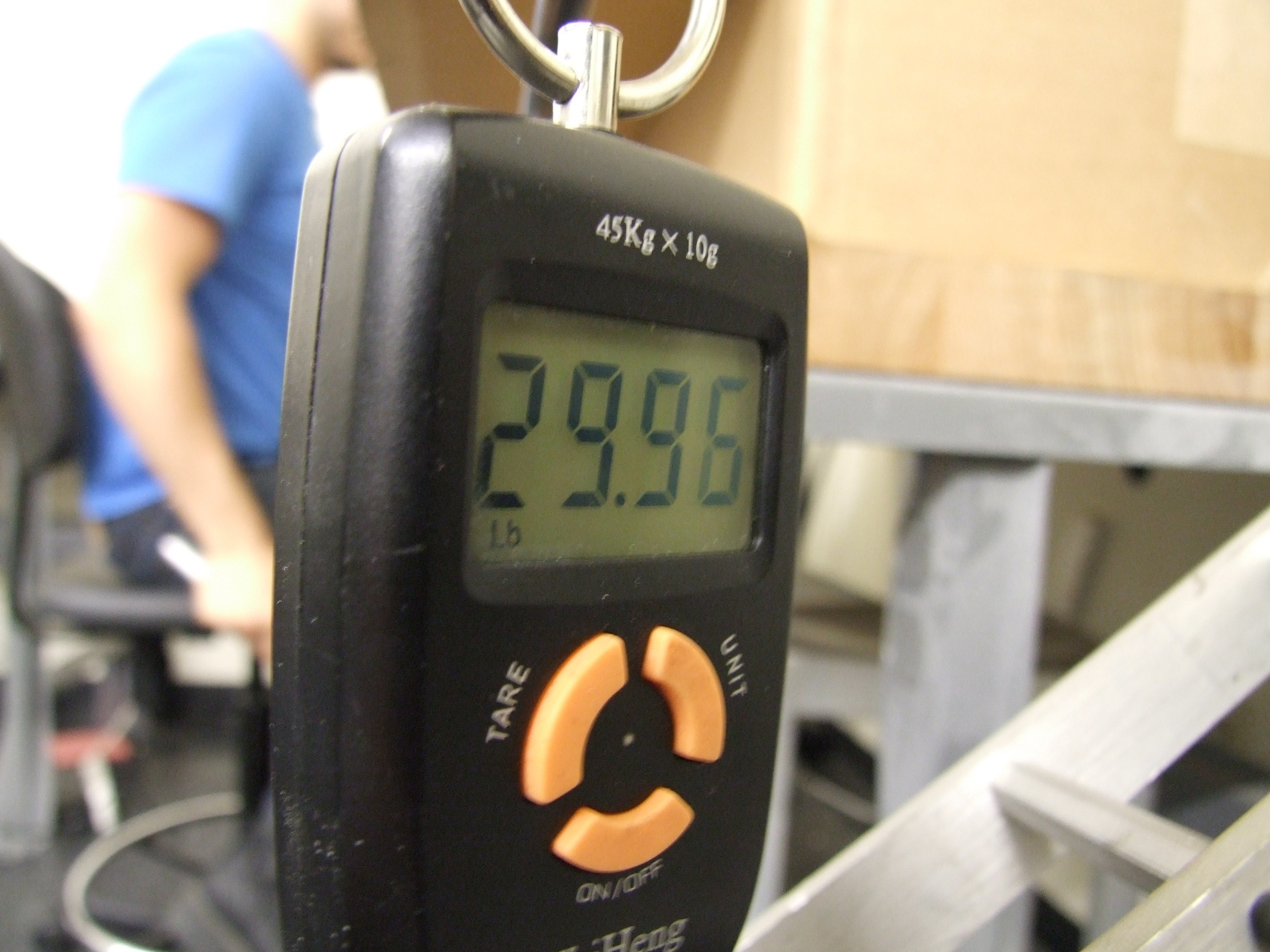
Yes.
That’s as close as I want to go. Generally, big event scales only read up to the 0.1 pound anyway, and some leeway is given at the organizers’ discretion to account for not everyone owning the same calibrated scales. So I should be able to add 5 or 6 more #4 button heads on the top plate without issue.
So, the final tally of changes was a few machined-hollow metal features and a battery change. While the battery change lost me 0.75 pounds in the rear, the front leg channels and side plate pocket combine to keep the C.G. basically where it is.
Finally, the press shot:

I spent way too much time driving this thing around and practicing with the fork. So far, the driveline has been perfectly reliable. The centroid CG placement and smooth braking of the RageBridges, coupled with the ultra-tight deadband, makes for one of the most smoothest-driving bots I’ve built.
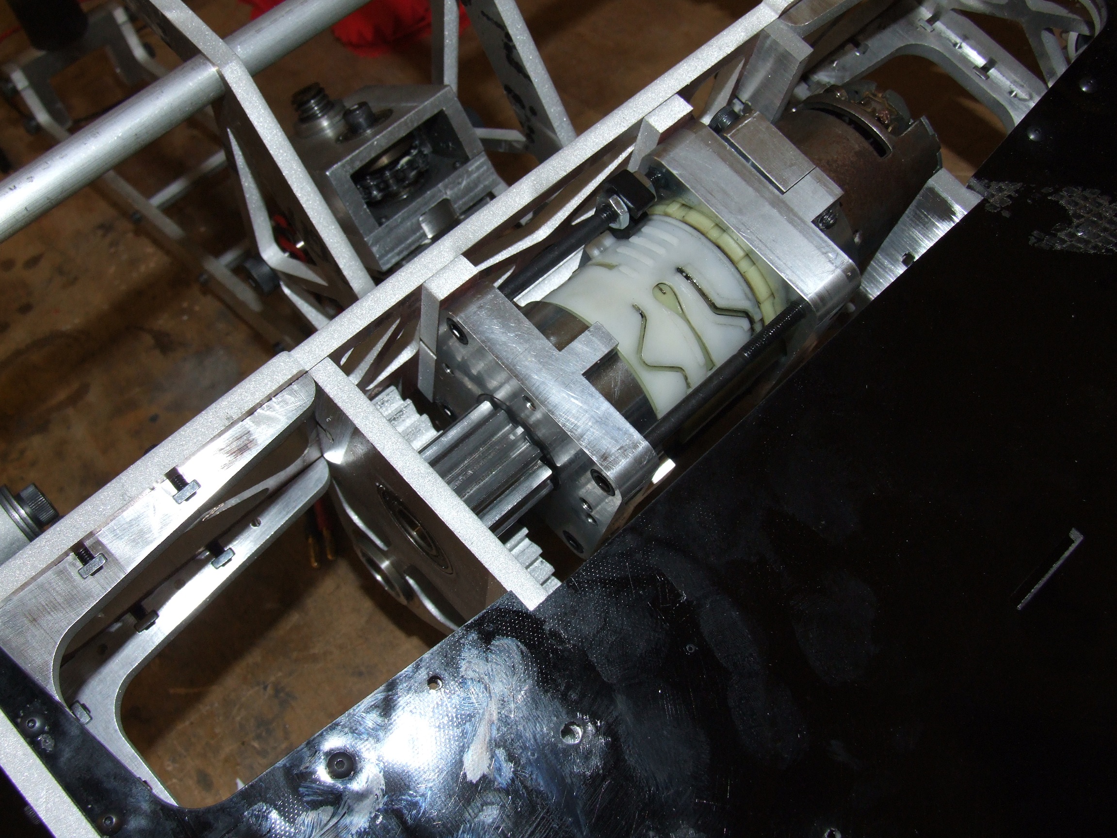
The “clock face” has been covered up with some thin polystrene sheeting that is normally used as thermoforming exercise stock. It’s just a dust cover, more or less.
One thing I experimented with was adjusting the torque clutch on the DeWalt gearboxes. My “DeWut?!” mounts have a set screw that can push in the torque clutch’s preloading spring, just like what the torque setting ring does on the drill body itself, so in principle you can create a torque limited drive. I’m glad to say that this is in fact possible in real life. I tried lifting stuff with the fork, but the motor just made angry drill sounds because I didn’t adjust out the clutch at all.
Luckily, this version of Clocker was built with serviceability in mind, and in under 1 minute I had the 4 screws undone, the motor slid out, the set screw tightened, then the motor remounted and the screws reinstalled. While I could have played the “How far do I turn the screw to lift a 30 pound opponent?” game, I elected to just let the current limit on RBs take care of maximum lift load, so I locked the clutch using the set screw.
My exercise regimen was mostly blasting in straight lines up and down the hallway. This was in fact not very easy – Dewalt must have changed their 18v motors’ windings very slightly at some point, because I have 2 allegedly identical 18v type motors that are definitely different ages, and they are very slightly different. They are different in speed enough, though, that Clocker still pulls a wide circle. For now, I’ve been just practicing it away with the radio, but I probably want to check for matching motors next time I have the bot open. I also engaged in a few short “drive a perfect square” laps, and “do a perfectly straight J-turn” also.
But Clocker has actual weaponry, so I’ve also been practicing attacks and methods using the fork and clamp. I’m fairly sure that now with the much faster clamp arm, I can catch and lift an opponent (or at least break its traction) in under 2 seconds.
Here’s another short test video using Null Hypothesis as a fork chew toy.
Notice how Clocker can hoist a 30 pound opponent pretty much hanging off the end of the forks. I attribute this to the much longer springy legs this time around, making the 2-bot complex much more stable as a result. I think in battle the lifts won’t be as smooth, and there will be much squirming on the opponent’s end, but it’s good to see that Clocker will no longer be as prone to faceplanting on a lift. The down side, in my mind, is that the legs are now a vulnerability because they stick out so far.
The tournament will soon tell all. Between now and Motorama, I want to get a few things done:
- Practice sparring with some of the other area 30lbers, Null Hypothesis, or the now mostly beheaded Clocker Remix.
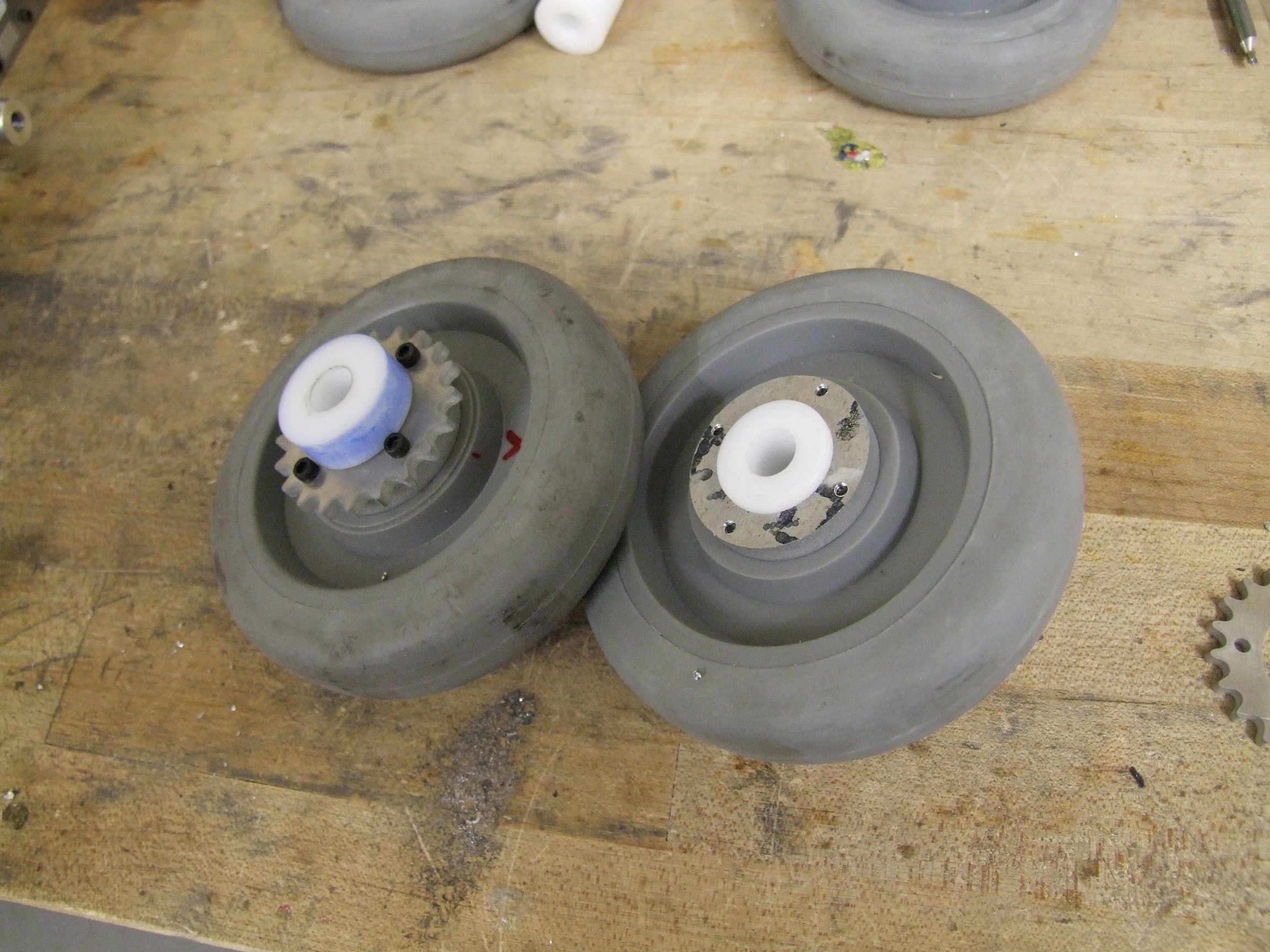
- Make spare wheels. I have 6 spare wheels, and I’m probably going to need all of them.
- Secure all internal wiring with some kind of adhesive or sealing compound
- Take nice pictures and make an assembly guide for the DeWuts! I plan to bring several to Motorama, so they must be ready by then. They will be up for public sale on e0designs.com after the event itself.
For the T-minus updates from here on out, I’m probably going to just update on practices and anything that breaks, plus maybe an opponents analysis when the event gets closer.