This will be the first half of two posts that will wrap up Cold Arbor’s build as well as sum up the robots’ performance at Motorama 2010.
The last two days before departure was spent seeking waterjet service for the custom sprockets and wiring up the robot with all the electronics. I ended up getting the sprockets cut about an hour and a half before we left for the event!

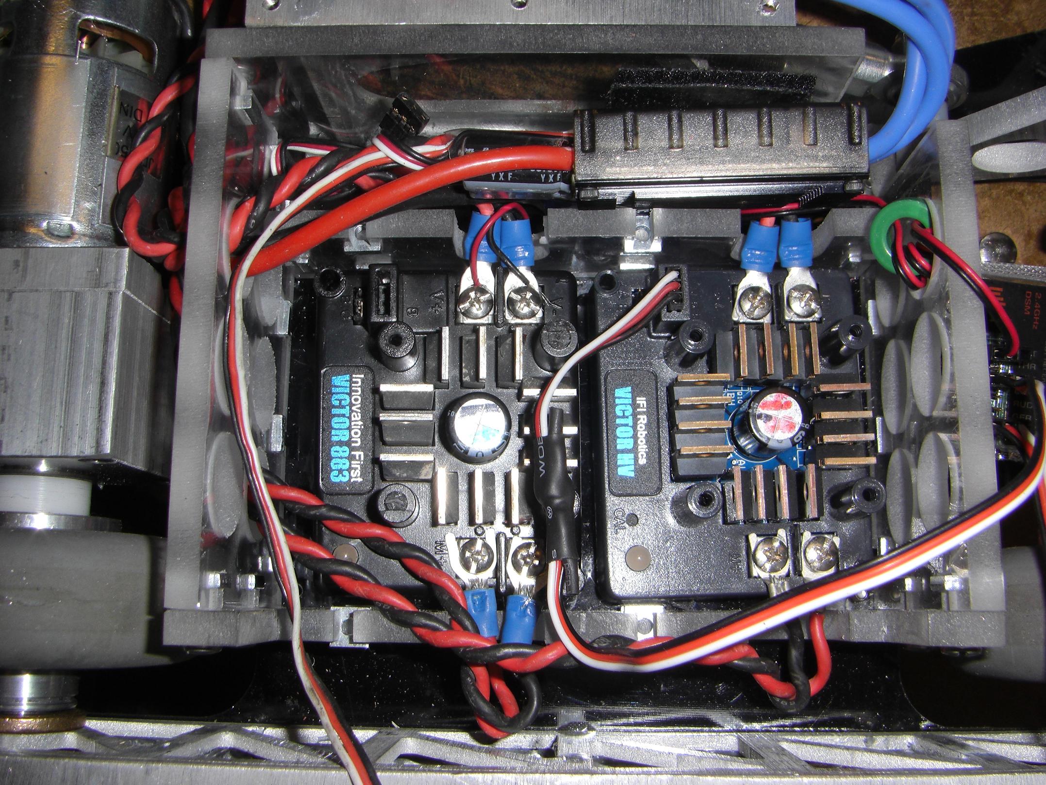
First off, electronics. Here’s the beginnings of Super Deansbus™ for Cold Arbor. I favor Deans (style, as half of these are knocks) connectors for their modularity and simplicity. Each actuator or major electrical subassembly gets its own tap off the Deansbus. It’s not as appendable as a terminal block or legitimate like a DIN rail distribution bus, but does this bot look like it has the space for a DIN rail?
Wiring begins on the other side with the installation of the Deathrunner controller and Victor drive ESCs.

Since Überclocker is hogging all the Victors which have boosters installed internally, I made a ghettobooster for the Spektrum receiver for Arbor. This is just two sides of a 74HC14 hex inverter chip. Each signal goes through two inversion stages so the original pulsetrain is recovered, but buffered to 5 volts, to the Victors’ liking.

I re-wrapped my spare 7S A123 pack since the heatshrink was becoming torn in places. I elected to use soda bottle armor for this pack after (finally) remembering that it exists.
For future reference, a 2 liter soda bottle is excellent hard-shell heatshrink for battery packs. They’re thin-wall polyethylene, but contract to become rather thick, and when cooled down, are practically plastic cases for your battery pack.
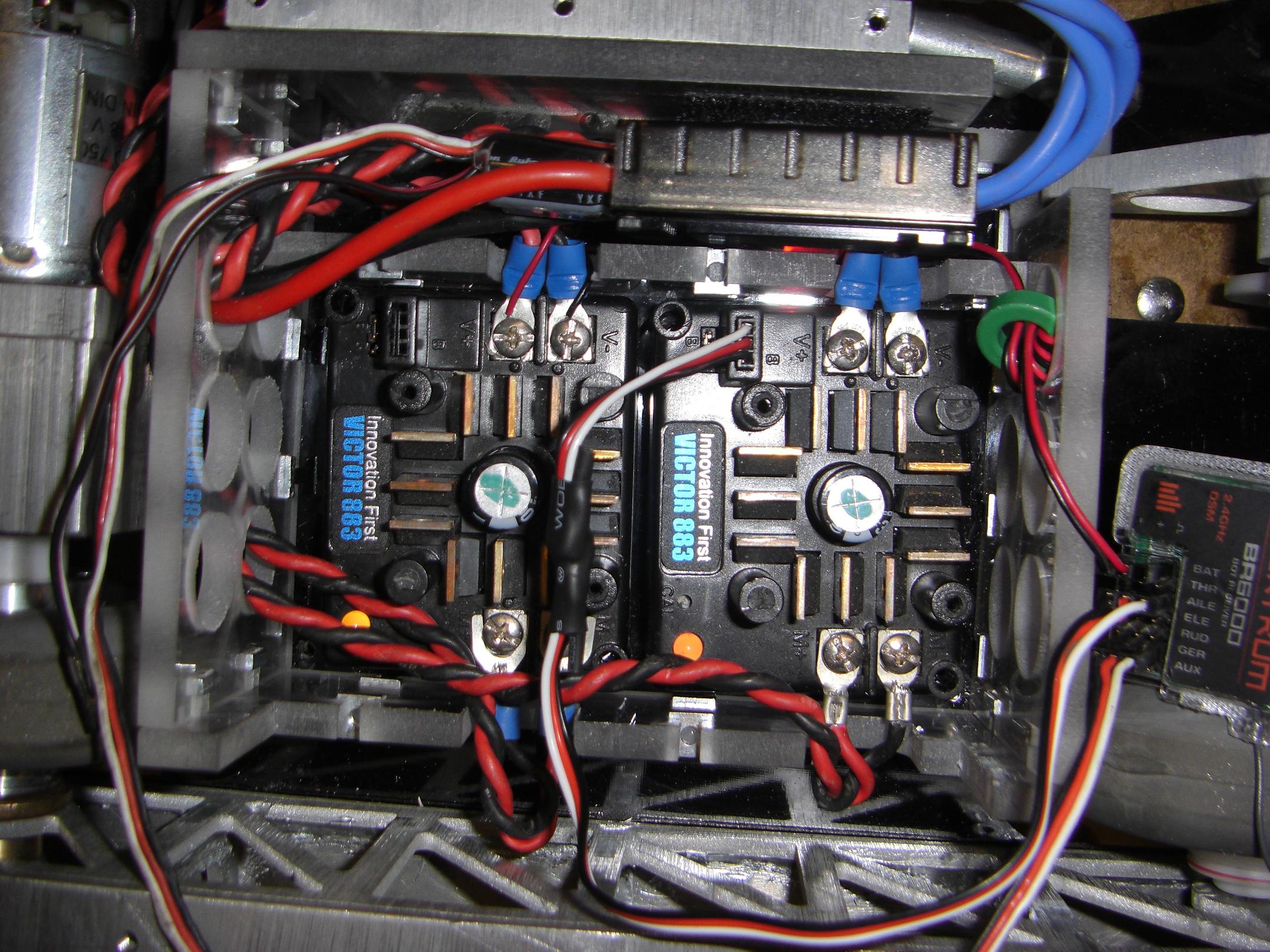
Remember the Ghettobooster? Turns out that it wasn’t necessary. My two Victor 883s didn’t want to talk to anything. Boosted or not, 5 volt native or not. Through discourse with my peers who also have had 883s lose their heads, the optocouplers were probably damaged. Since they were buried under layers of silicone potting compound, repairing on the go was essentially ruled out.
Uh oh. Thus began an epic Victor-hunting quest to find two working controllers for the bot. I went as far as to get a friends’ help to scour the Graveyard of MIT FIRST Robots, knowing they all used the same controller type. Alas, all the fresh ones had already been stripped, and the only finds were ancient Victors, at least from 2002 or earlier. Which, as I found out the hard way, were not rated for 24 volt operation.
They started to smell weird, so I stopped before permanently breaking something.

I had this extra fifth controller which was purchased with a damaged case. Initially, I stripped the case, then put it away and forgot about it. It powered right up and even accepted signal.
I also had one Victor HV on standby from Überclocker.
So, decision time… Swap out ‘clocker’s Victor HV and run a matched set? Unfortunately, it was buried in pretty deeply, and I didn’t want to risk damaging a full working bot.
And so that is how Cold Arbor got one shady junkbin Victor 883 (placed into the pristine case of a signal-deficient unit) and one Victor HV. The difference between the two is amazing. The 883 has a 10% minimum throttle deadband, but switches at around 2,000Hz. The HV has a tighter deadband, but runs only 120Hz. Every time it starts, the whole bot resonates.

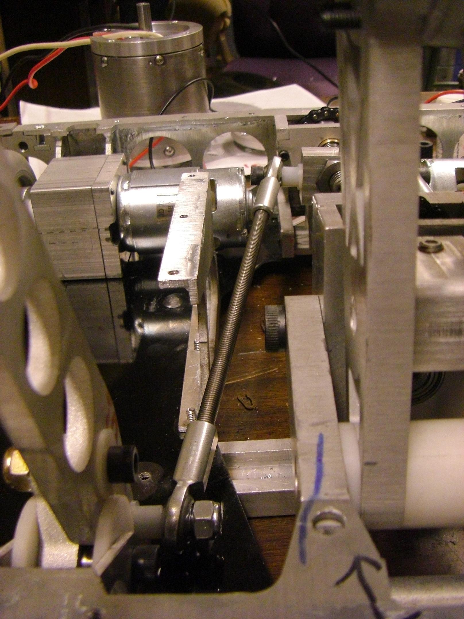
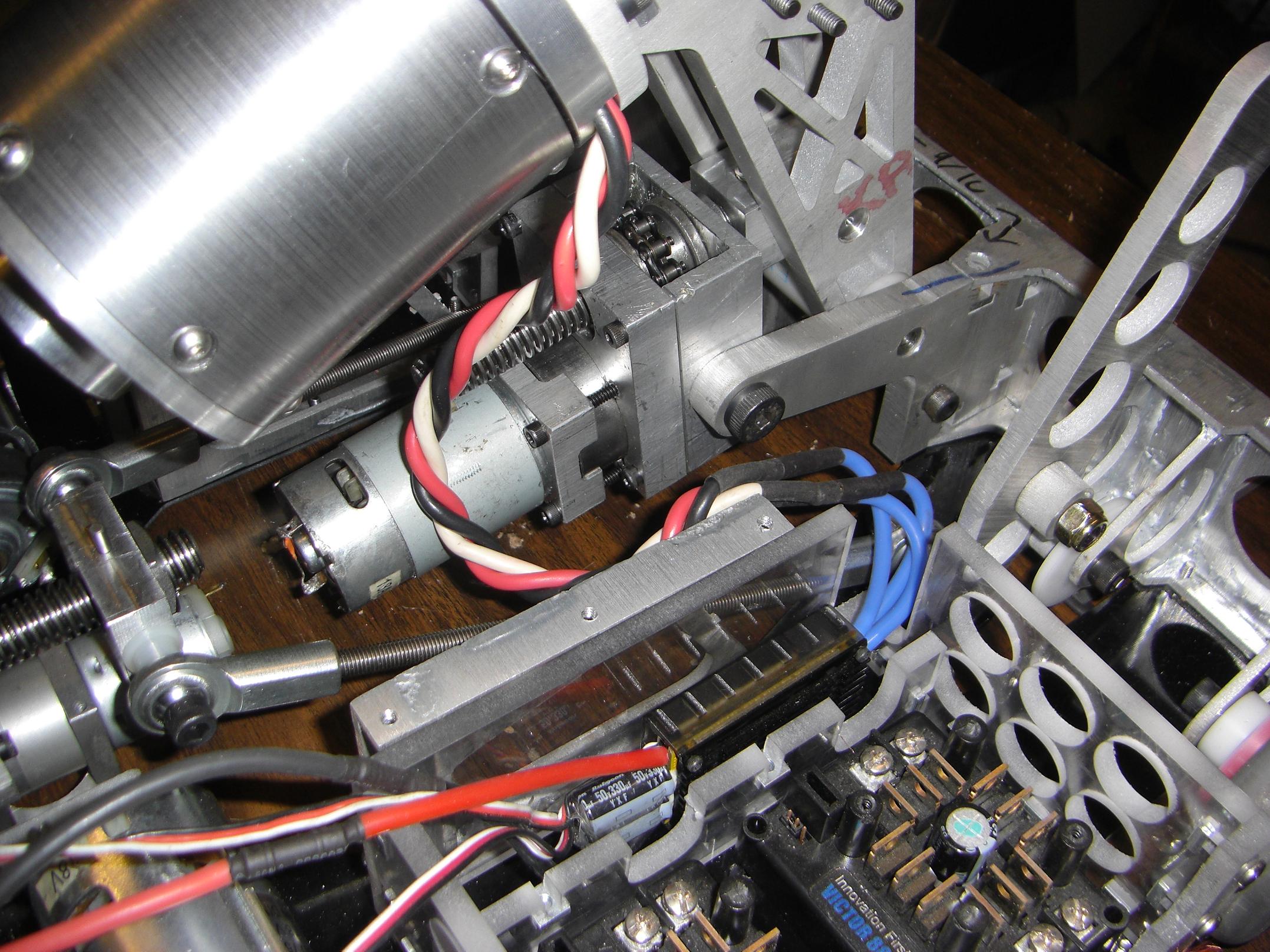
After the Vics were wired, I put in the upper control deck. It’s a single 1/8″ aluminum plate which has mounting holes for Dimension Syren 25 ESCs. The controllers will use the plate as a heat sink.
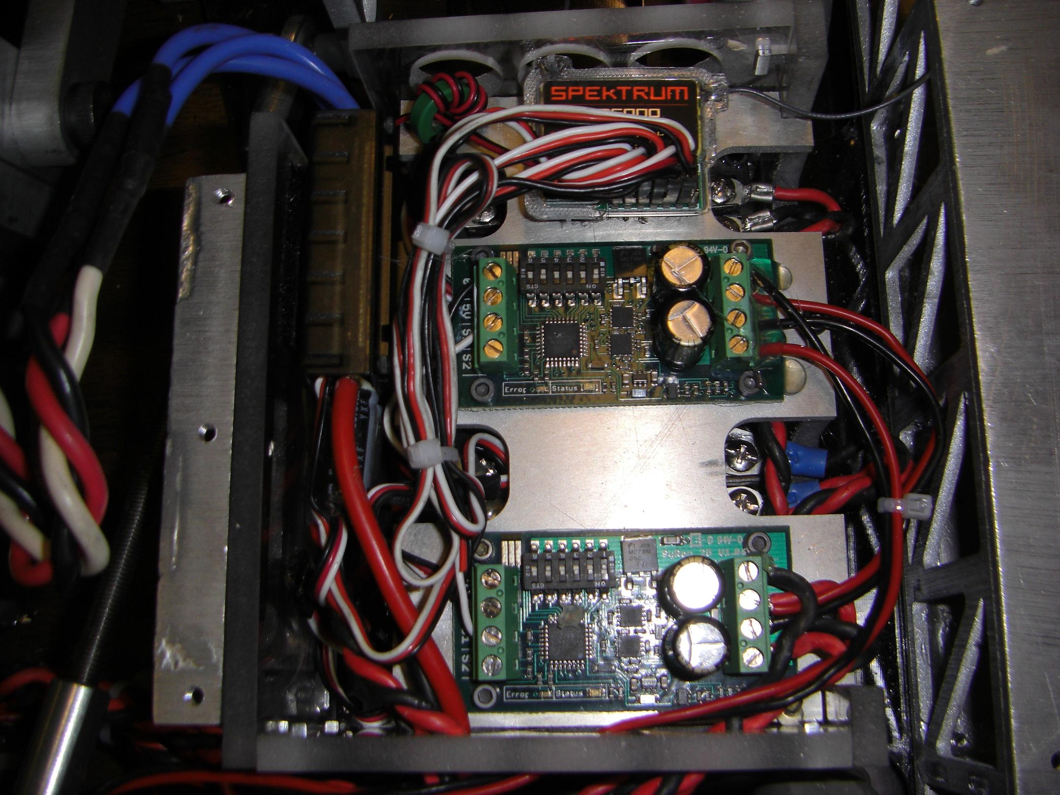
One controls the clamp motor, the other controls the saw actuator. I made sure the gaps in the plate were such that I could still access the Victors’ screw terminals.
The calibration button, on the other hand… Yeah, let’s not talk about that.
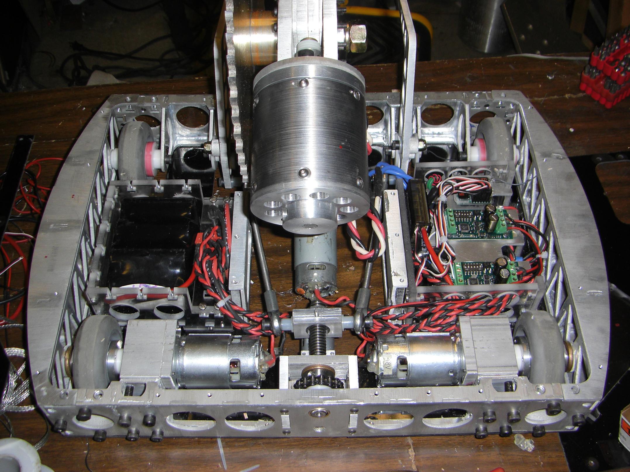
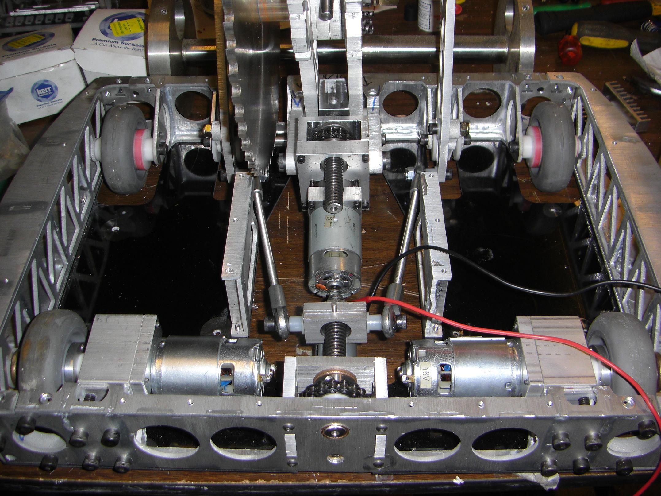
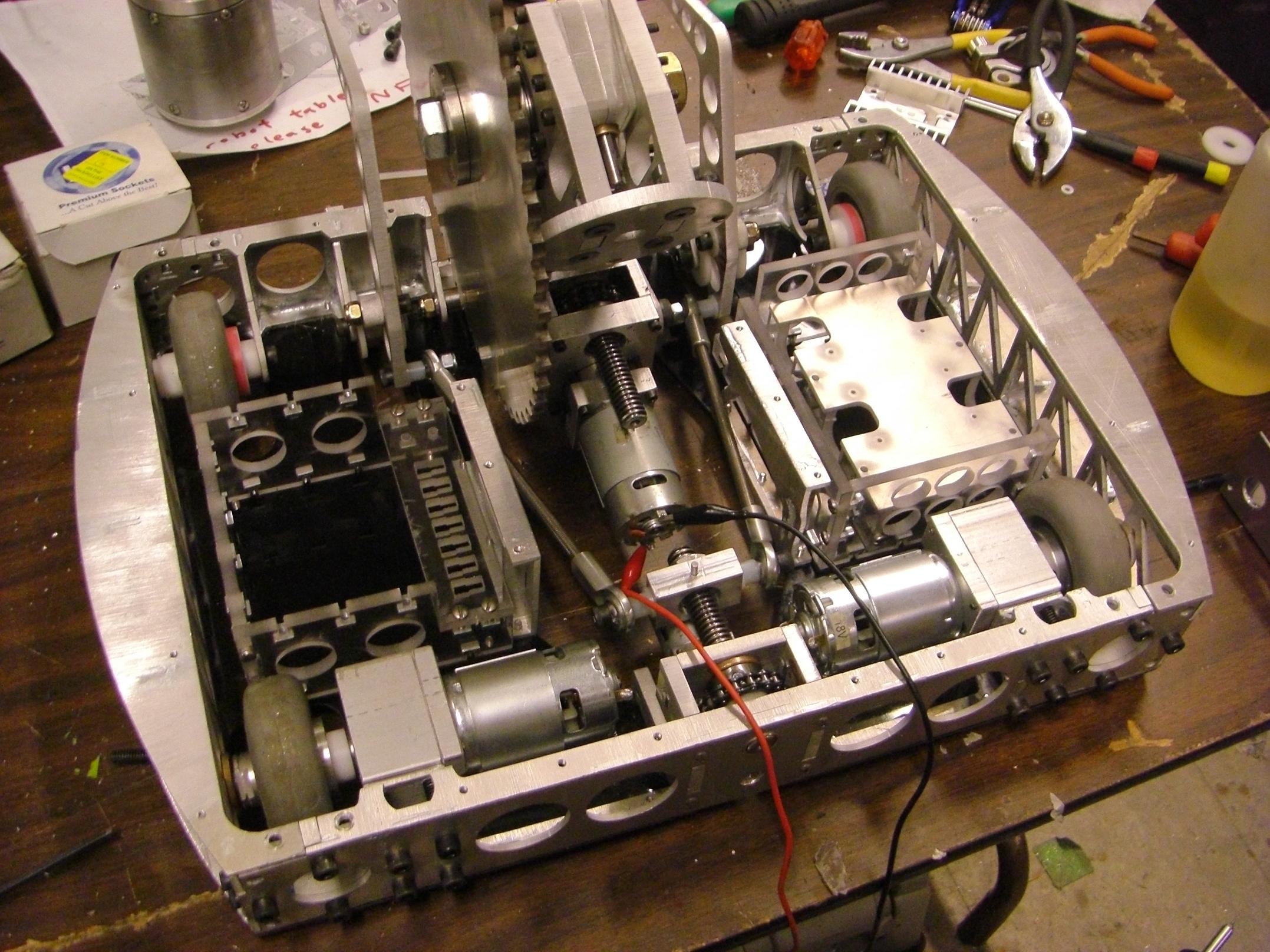
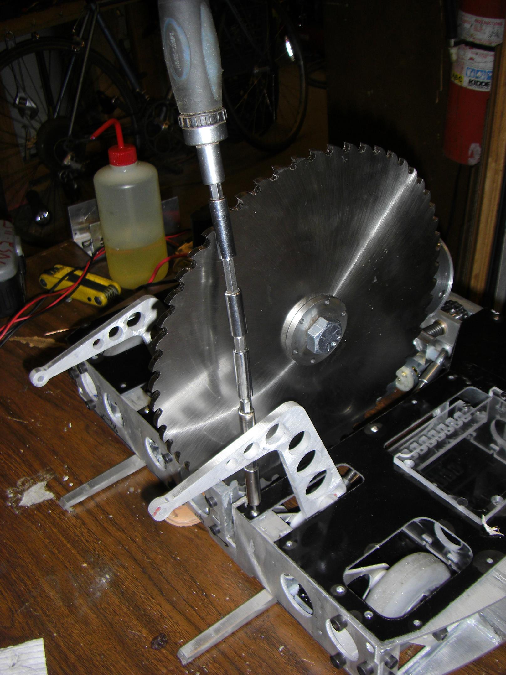
An overview of everything wired up and ready. Arbor was just missing the four D-bore sprockets at this point.
I tried test driving the robot in this state, but with much of the robot’s weight up front and the front wheels not being driven, it just sort of awkwardly castered around everywhere – not really driving.

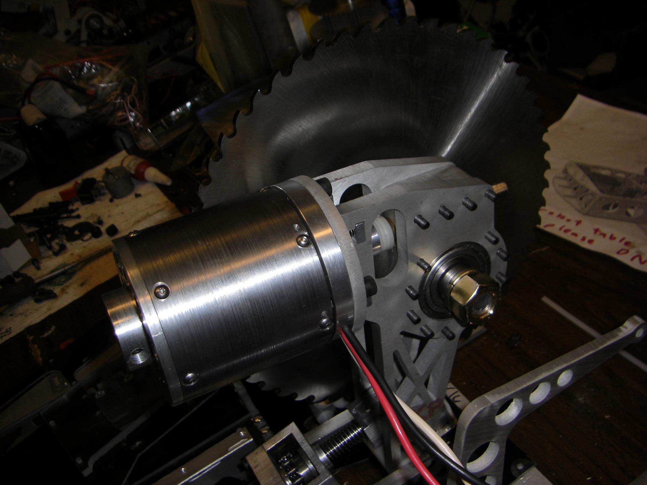
At about 4PM Friday afternoon, I finally had a chance to get some machine time, and quickly popped off the drive sprockets. I chamfered them out on a belt sander and quickly tossed them on the robot. It was the smoothest installation ever, since I had oversized the sprocket bores and purposefully undersized the hub diameter.
I’ll have to remember to keep doing that. The sprockets are aluminum instead of steel but…. who really cares?
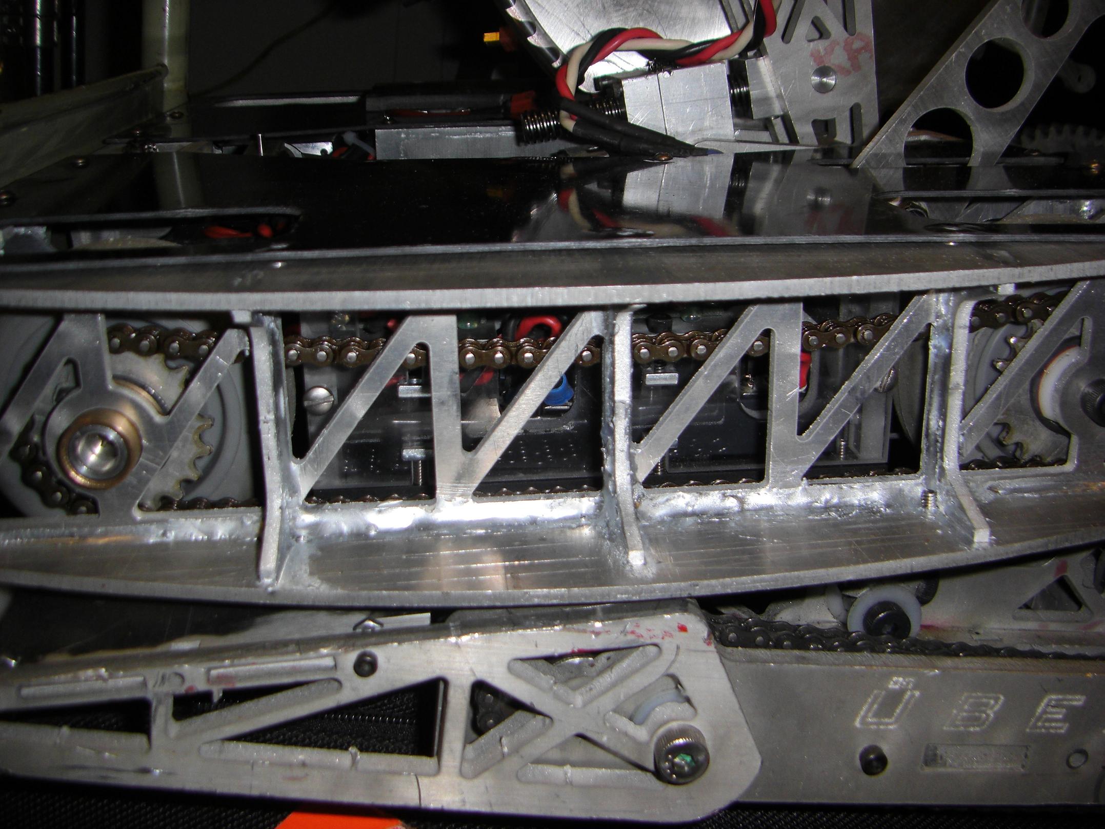
I forgot to take a picture of the drive chains installed until after I already loaded the bots up, but… here’s a picture of the drive chain. Installed. You know, between two sprockets.
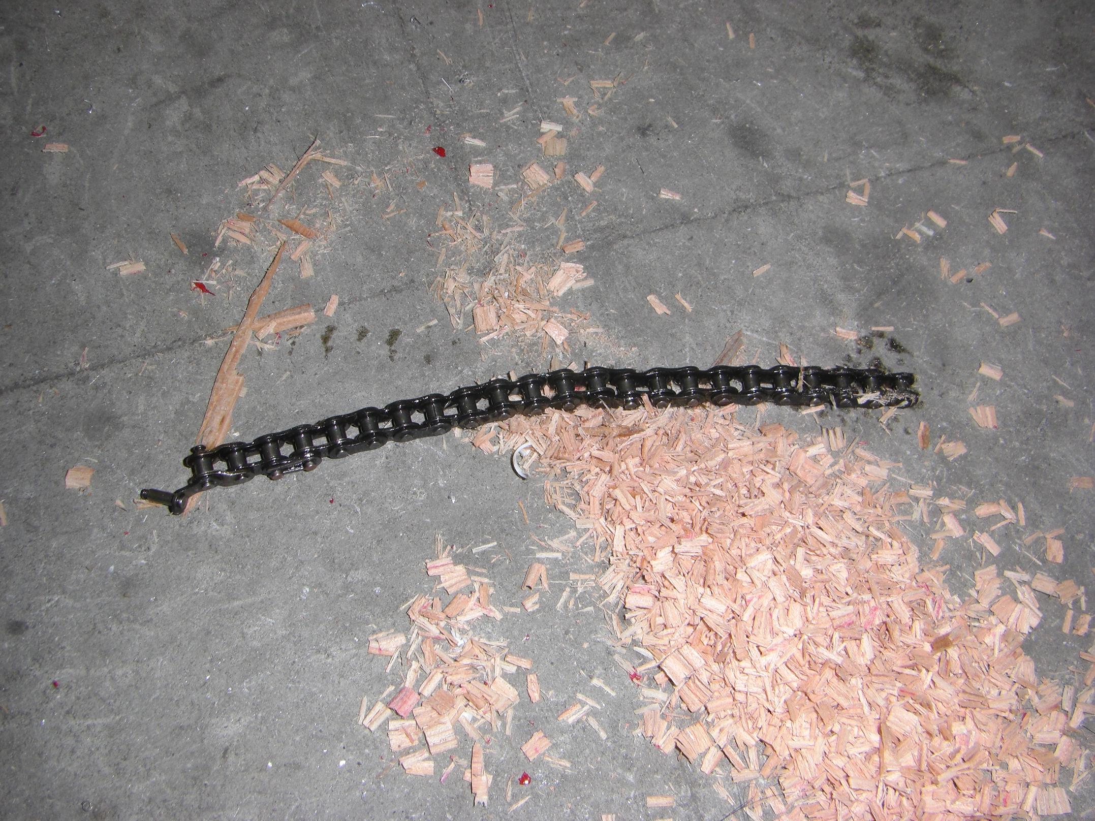
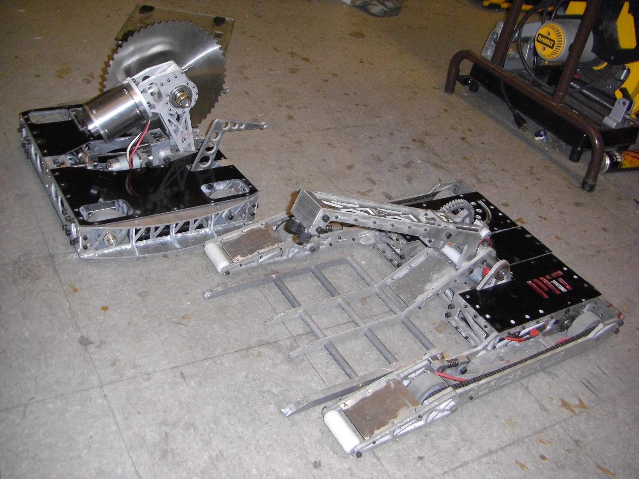
Here’s the result of some late-in-the-day testing!
That’s the actuator chain lying on the ground, very bent and broken. And a pile of saw chips from the wooden 4×4 that I cut up with Arbor.
I neglected to check how far the saw actuator’s mounting screws stuck into the gearcase (or would it be the chaincase here?). Because the chain was a short run, and thus untensioned, it some times jammed and locked up against the protruding screw threads. When this happened with the motor running at full tilt… well, the master link explodes in spectacular fashion.
The solution was just to grind down the screw thread length a little, and also round the end off. I threw on a new master link and the actuator worked again.