Poor Tinytroller.
Ever since it demonstrated open loop voltage control competency, I’ve been on a cycle of periodically destroying it and then repairing it, only to destroy it again. I’ve finished writing the current control software, and testing it has been quite the power-supply-crowbarring adventure. There’s not really any pictures since it’s been all software work , but I did put together a bunch of cheesy videos that demonstrate fairly well the difference between real closed loop current control and open loop “knob control”. Basically the short story is current controlled Arduino brushless motor controller!!!, but the gory details…
yesterday
Starting with the functional motor commutation code which just piped an ADC value (the pot) straight through to PWM, I implemented a current reading method that Shane pulled out of his ass Arduino (because he loves software). In a DC motor, current sense is easy since there is only one path for the motor current to flow. But, in a square wave commutated 3 phase motor (or classical “brushless motor”), there are six possible ways: the combination of “out one phase and back in another” for any 2 of three phases (3-choose-2).
If I had 3 current sensors, that would be still easy. But in the interest of saving board space, Tinytroller has two current sensors, on the outputs of phases A and B. Therefore a little trickery is needed in order to sense steady state motor current, since the state of the motor and therefore the path of the current is always changing, and there are times when either A or B sensors are not in the current loop at all, such as when their respective phases are off.
I made an array of current sensor “gains” which were later to be multiplied with the raw reading and the result summed. In the same interrupt-driven state table, I modified those gains according to which sensor should be conducting, in which direction, in any given state.
In the setup:
...lalalala
volatile signed char isense[2] = {0 , 0};
...etc

In the interrupt:

get state...
switch(state) {
      // 0 0 1
      //isense: A out
      case 1:
        drive pins...
        isense[0] = -2;
        isense[1] = 0;
      break;
      // 0 1 1
      //isense: B out
      case 3:
        drive pins...
        isense[0] = 0;
        isense[1] = 2;
      break; ...and so on
Later on,
i = I_RC * (IFACTOR * (float)((isense[0]*rawia + isense[1]*rawib) >> 1)) + ((1 - I_RC) * i);
Each state has corresponding “gains” of +2, -2, or 0 such that my resultant reading is a continuous value after summation. The only exceptions are 2 states where A and B are the active phases.
//isense: A out B in
      case 5:
        drive pins...
        isense[0] = -1;
        isense[1] = -1;
In that case, the gains are both 1 such that they sum equally. The right-shift is used as a quick division-by-2 to recover the actual current reading in both cases. Because phase A’s current sensor had to be inserted backwards to fit on the power board, it’s always being used in the negative sense i.e. when A phase is pushing current, the reading is negative.
In other words,
State     Out Phase     In Phase     Ia     Ib
1         A             C            -2     0
3         B             C            0      2
2         B             A            1      1
6         C             A            2      0
4         C             B            0      -2
5         A             B            -1     -1
To smooth out the reading, the current reading is actually a first order low pass filter with I_RC as the smoothing factor. Without it, the i reading is erratic when the motor is running at high speed. IFACTOR is a constant that shifts the summed ADC values into ampere units – while it isn’t necessary at all, I find it more intuitive to think in the actual units being controlled for now.
The actual current control is deceptively simple:
cmd += (IGAIN * (rawcmd - i));
The reason that the command is constantly incremented is because simple current control of a motor is pure integral (I) control, and is analogous to a constant ramped voltage (which is why ramping up a motor by slowly increasing voltage is essentially like it, unless the inertia or load changes). I can get faster current transient response if I use PI or the whole PID, but software (and possibly current sense noise and bandwidth limitations) means I’ll probably keep it this way. rawcmd is a shifted and scaled version of the throttle input reading, again to get it into “amps” units.
rawcmd = (((IMAX - IMIN) / (float)CMDMAX) * ((analogRead(AIN0) - THRMIN)*(CMDMAX / (float)(THRMAX-THRMIN)))) + IMIN;
If I left ifactor and the current scaling out and changed igain accordingly, that would save some floating point operations.
What it does mean is that it will never settle to the current setpoint, but sort of bounce around it. This is felt during stalled motor tests as a small vibration (torque ripple) as the output PWM command integrates over and under the desired. With tight gains and fast filters, plus ass mass to damp it out, it’s negligible.
All that being said, it’s MITERS Public Etek time. I clamped it to the table and after some more debugging, took some video of a knob being turned:
The reason it is able to quickly brake is because I can actually set the current control endpoints (max and min currents) to be either positive or negative. For that test, the maximum positive current was 40 phase amps, and the minimum current was not zero (which would cause the Etek to spin down at the rate it would if it were just disconnected, something that is seen in the video) but actually -5 amps. It also means that zero on the potentiometer is not zero – it’s actually trying to pull 5 amps out of the motor constantly, and if I spun the Etek with another source of rotation (like another Etek) it would apply enough load torque to that speed source such that Tinytroller was slowly charging my test battery.
Zero current is actually somewhere along the pot rotation, and at that spot the Etek will freely rotate in one direction (like it was disconnected). Rotating it by hand the other way is a hard brake because the state table causes the phases to switch to oppose it. To get true bidirectional coasting, I’d need a speed feedback on the motor so I can tell which way it is trying to spin and decrement the state table accordingly.
For giggles, I stuffed it into the neutered Straight RazEr, with its sensored, rewound melon from a previous Landbearshark drivetrain, and set it for a maximum current of 20 amps and minimum current of -1 amp, such that it naturally tended to drag brake to a stop. I discovered why melon-LBS never worked: The sensors are horrifically mistimed. So much that my 20 amps only was able to maintain a roughly brisk walking cruise. Ouch.
The actual current scaling gain was calibrated with a clamp meter and it appears to be within 1 amp of the actual current at all times. I am more than satisfied.
Result: Tinytroller is alive!
today
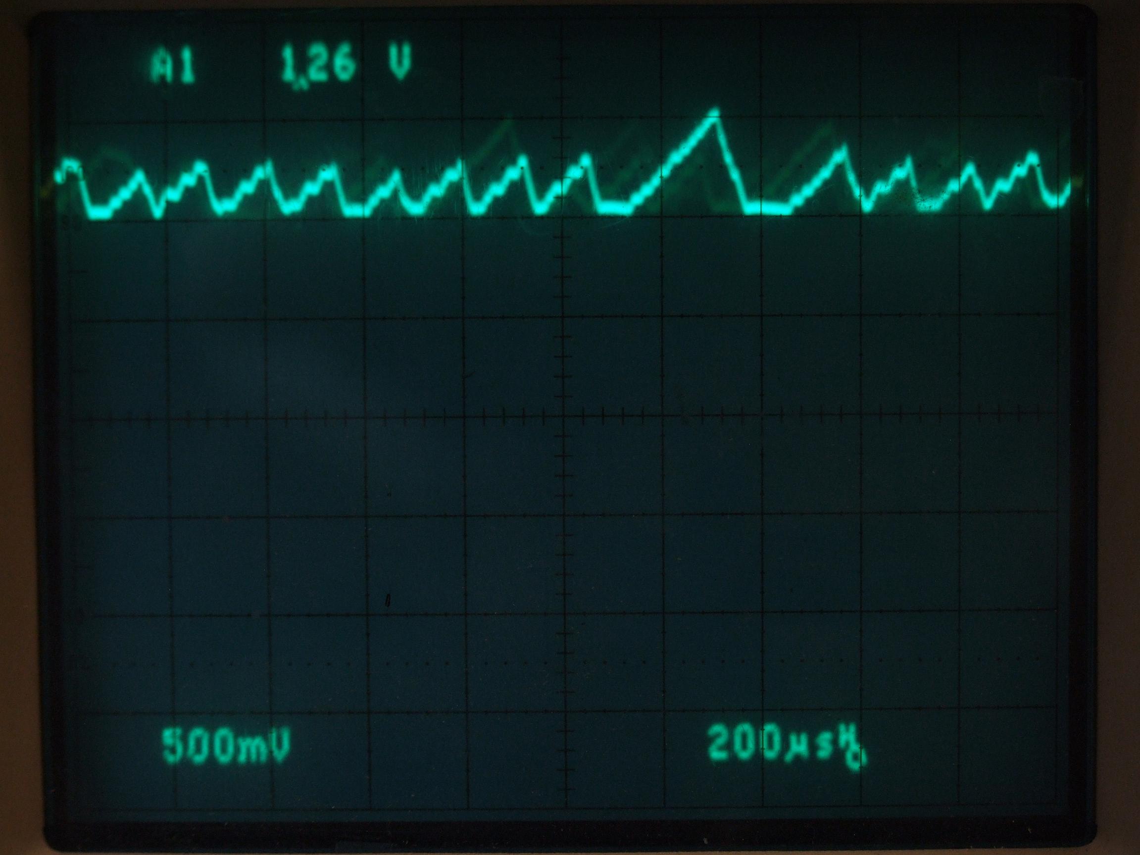
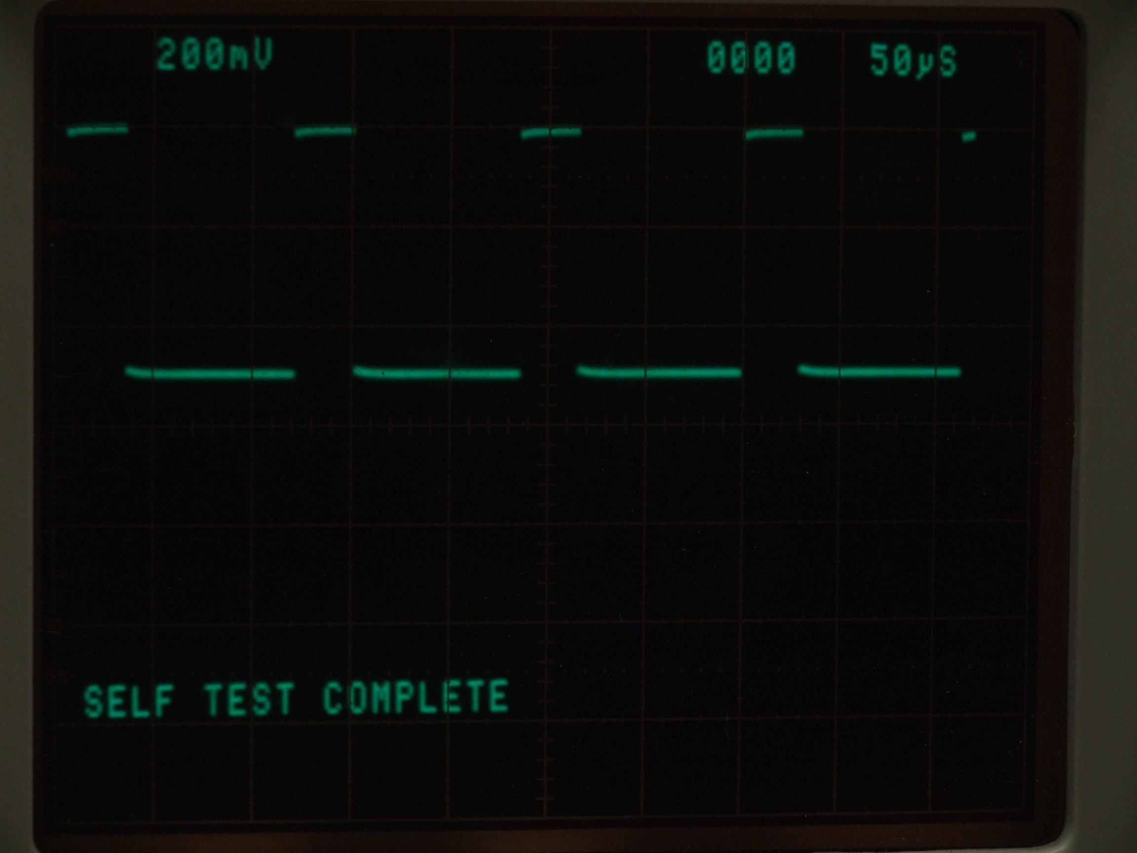
I had only one issue with the code from yesterday. It worked great, and did the thing it was supposed to do. But my main loop runs however fast it wants to – only the interrupt is guaranteed at 7812.5 Hz. Problem was, all of my time constants and filter damping factors depended on a fixed delta-t, and therefore they changed as I added and took out debugging Serial prints. Using the same toggle-a-pin as the interrupt, I watched on a oscilloscope as my loop went from 1.8 milliseconds per execution with no Serial printing to 4.3 milliseconds when I had the Arduino recite everything to me. That made a massive difference in terms of how twitchy the control was and how fast the system responded to my commands. Two important constants depended on having a fixed loop time: IGAIN, which is the “number of amps to increment per loop cycle” based on a desired maximum amps-per-second ramp rate, and I_RC, which is the low pass filter recurrence relation factor
In lieu of setting a watchdog timer or using another timer’s hardware interrupt, I used a dumb software hack (uh oh, so it begins…):
To setup…
#define MAIN_LOOP_PRESCALER 16
volatile byte ninjaPrescaler = 0;
And in the interrupt,
  if(ninjaPrescaler < MAIN_LOOP_PRESCALER) {
    ninjaPrescaler++;
  } else {
    ninjaPrescaler = MAIN_LOOP_PRESCALER;
  }
Which is used by the main loop…
if(ninjaPrescaler == MAIN_LOOP_PRESCALER) {
    ninjaPrescaler = 0;
do all the important crap here }
So there. My main loop now runs at about 490 hz, coincidentally the default PWM frequency of the Arduino. In the periods of time it is not doing anything, I inserted the stuff that doesn’t matter, like a Serial write or two. I recalculated and adjusted the filtering constants such that now the filter response times are actually determinate.
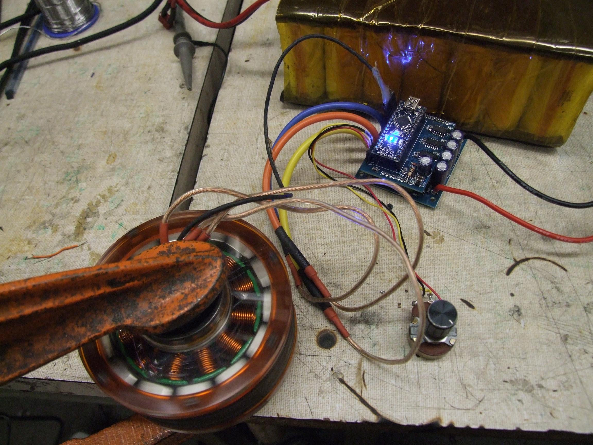
With that code prepared, I threw it back into the Etek, this time with some extra inertia for giggles.
The big spur gear is a Swapfest find of many moons ago, but it finally has a legitimate(?) use! It works the same as before, but now it’s more predictable. With the Etek-flywheel giving the system some extra push, I turned up the maximum and minimum amps to see how Tinytroller handles some more serious regen, and it passed the -20 amp regeneration test flawlessly.
And then I put it on a power supply.
I’m not even sure why I did that. I may have been meaning to up the voltage from the 24 volt test battery to see how Tinytroller likes hard braking at higher voltages. But what I forgot was that power supplies do not accept current donations – unlike a battery which charges if you feed in current, power supplies only have output filter capacitors as a buffer – and the more current you feed a capacitor, the higher voltage it becomes. When Tinytroller tried regenerating 20 amps into the bench power supply, the resulting current spike destroyed my gate drivers. Everything just sat there drawing a constant 20 watts or so as the chips dissipated it all and my 15 volt regulator became very unhappy.
Result: Tinytroller is dead!!!
I hurriedly replaced the IRS21844s and went to test it again. However, in another moment of boneheadedness, I had neglected to reset the power supply. One of my methods of debugging is “turn up the power supply until whatever thing is damaged lights on fire” – it’s a pretty sure fire way to determine what part is dead. During the initial “20 watt burn off test”, I kept upping the voltage on the power supply to see how much current it eventually wanted to pull, but the current limiting on the power supply kept the voltage from changing significantly.
No longer true after my parts were repaired, the PSU immediately shot up to full voltage on connect (Oh yeah, did I mention I neglected to actually disconnect anything to replace the parts?). This would be fine with most of our PSUs which only peg at 30 or 40 volts, which Tinytroller’s FETs and LM2594HVM can all take. Except I was using the 100 volt power supply because …. why was I using that again?
Instantaneous destruction of 3 FETs, all 3 replacement IRS21844s, and the LM2594 which actually lit on fire. I thought the Arduino was completely destroyed too, but the 5 volt TVS I had installed as a noise protection measure saved it in that brief instant. Well, not really – the micro was fine, but the FTDI USB interface chip was toasted.
Result: Tinytroller is still dead!!!
I replaced Arduini, gate drives, FETs, and regulator again, and this time was able to have some more fun with Tinytroller (ITS ALIVE!!!), but with negative current disabled for now. And then inexplicably, everything died.
Selective probing found that the new LM2594 had someone failed through – as a high side switching chip, this means it flooded the downstream circuitry with 36 volts. This time, no amount of zenering could save anything, and I lost the Arduino, drivers, and all six FETs to blown gates.
Result: Tinytroller is dead again!!!!
Whatever. Clearly there was something else on that board which was damaged by the overvoltage spike that I did not catch, or was improperly replaced. After the way-out-of-spec overvoltage, I should have just scrapped the board and started over. It was clearly a sign of retribution from the robot gods for me having too much success with software.

I’m out of Arduino Nanos, but have just enough of the limiting reagent to make another Tinytroller board. Because it looks like the software problems are resolved and the hardware problems have been reduced to engineer is a total dipstick, I will indeed go ahead and make a third board.
But wait, there’s more!
Here’s a new signal board for Tinytroller.

Isn’t that the same thing? Mostly so, but I’ve rolled up all of the noise hacks (TVS, logic decoupling capacitors, ground splitting resistors) and added phase voltage sensing!
That’s right, all 3 phase voltages are fed through voltage dividers with RC filters and are accessible to the ADC. With phase voltages and phase currents available, maybe I can now do something about all those problems I keep having with sensors.
Sensorless Tinytroller?!
For the morbidly curious, Tinytroller’s Arduino sketch.