


First, these videos must be watched before I can explain what the hell is going on:
Anyways, the arrangement of the gears in this contraption is known as a compound planetary geartrain. The idea is not unlike a harmonic drive – the difference in tooth counts between two ring gears is exploited by a rolling constrained element inside. However, unlike the harmonic drive, or the chainarmonic drive, there is no deformation element – in the case of the harmonic drive it’s the strain in the flexible spline, and in the chainarmonic drive, well, it’s a fucking chain.
Either way, the method has been in use for quite some time to get a ridiculous gear ratio in a small space – it has historically been seen in winches, bicycle hub gears, turboshaft engine output gearboxen, and apparently also automotive power mirror adjusters as the Wikipedia image shows. It’s also the secret of how the 2.007 kit motors, the BO-P5 and BO-P6, drop a 40:1 and 120:1 respectively in two stages of gearing, if you even count the output ring gear as a “stage”. Normal planetary gearboxes are hard pressed to get 7 or 8:1 in one stage, and that is with the sun gears being tiny and comparatively fragile.
But what is the actual gear ratio of a compound planetary geartrain of the type shown in the Wiki table of planetary gearbox arrangements, row 4 column 3? I’ll drop it here in case Wikipedia ever disappears or that page gets troll edited:
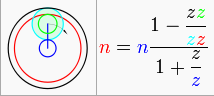
where blue indicates a driving element, green and cyan indicating small and large idler gears respectively, and red indicates a driven (output) element. Black indicates a fixed element. As can be observed from the diagram, this is the classical ‘compound planetary’ arrangement of a fixed ring gear, rotating ring gear, sun gear, and two idlers of different tooth counts.
…or is it? I spent a while staring at this trying to figure out why the blue carrier stick was…. well, blue. I decided that this must have been a graphical error – if the carrier were forced to rotate with the sun gear at the same speed, there would never be dependent rotation of the planets at all. However, there was another arrangement which lacked a graphical error and seemed more plausible at the time, and it is row 5, column 4:
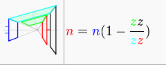
This is a strange illustration for sure. I’m not sure why the wikipedia editors chose to make a strange arrangement of bevel gears which nobody in their right mind would actually try to build – I’ll chalk this one up to Wikipedia being crowdsourced. But topologically speaking, this is equivalent to the former diagram. The blue input sun interfaces directly with the cyan idler which is constrained to the fixed ring gear, and mechanically locked to the green idler, which drives the output gear. So why was one including an extra factor of 1 + (z_fixed / z_driving)? That expression, 1 + (z_fixed/z_driving) is exactly the ratio of a single stage conventional planetary with carrier output.
I wasn’t sure which one was wrong or right, so I decided to try out both in Inventor using rotational mates and the model of the first (104:1) gearbox. The result clearly showed that it is in fact the former, which really says that the diagram is wrong because it indicates the blue carrier stick as being rotationally driven. In actuality, the carrier just holds the idler gears and should ideally not experience torque. What this experiment told me was that if I used a conventional sun gear input and fixed ring for the first stage, the compound planetary ratio of ( [z_small_idler * z_fixed] / [z_large_idler * z_output] ) is multiplied by a further conventional planetary gear ratio of 1 + (z_fixed / z_driving) …even though it superficially looks like division – the compound ratio is 1 – (something close to 1), resulting in a very small number, further multiplied by a 1 / (large number, the conventional planetary gear ratio) resulting in a number smaller still.
This means either I am misunderstanding the distinctions between the two diagrams, or that they’re wrong. I’m not quite confident enough to say the latter, but regardless they’re really, really wack, bro.
Empirically, then, the ratio is confirmed to be of the form 1-(z_small_idler * z_fixed)/(z_large_idler * z_output ) / 1+( z_fixed / z_driving) for tooth count z.
I now present converse method of determining the gear ratio from Shane Colton, who can put up with infinitely more math and basic mechanical physics than I can:

This is pretty much all going up because we determined that about a year from now that entire conversation about compound planetary gearbox design will have been forgotten and therefore have to be rediscovered. Now, I definitely don’t want to go through all of that again, so I will say that the speed equation on the bottom left, of the same form as the Wikipedia equation, can be algebraically transformed into the torque expression in the top right (appropriately inverted to change to speed instead of torque). It’s missing something, though, namely anything involving the fixed ring gear.
Right away, it can be seen that R5, the diameter of the fixed ring gear, can be eliminated as a design input, reducing the system to four degrees of freedom. This is because the ring gear is assumed to be as large as the sun plus a plant – in other words, R1 (sun) + 2 * R4 (first stage, larger planet)… From a pure radius equivalency perspective, this makes sense. If these were pitch circles of gears, then the ring gear would have to be exactly one sun radius plus one planet diameter.
Therefore we define the Soft Rule as follows: The ring gear pitch diameter must be one sun pitch radius plus one planet pitch diameter. From a tooth count perspective, this means the ring gear tooth count must equal the sun gear tooth count plus 2 * first stage planet gear tooth count – or concisely, Z_s + 2 * Z_p1 = Z_r where p1 is the first stage planet (previously called z_large_idler). If soft rule is obeyed, then you only select the sun tooth count, planet tooth counts, and output ring tooth count: four degrees of freedom. Why is it called “soft rule”? Because…. yeah.
The speed ratio with 4 degrees of freedom is then 1-(Z_p2 / Z_p1) / 2*(Z_r2 / Z_s) where r2 is the second stage output ring gear.
However, there is another dependency which can be eliminated in order to simplify ratio selection even further. Let the radius of the output ring (R2) equal the radius of the sun (R1) plus the radius of each planet (R3 + R4). From a tooth count perspective this is Z_r2 = Z_s + Z_p1 + Z_p2. Geometrically, this is saying that the difference in tooth count between the ring gears is the same as the difference in tooth count between the planets, which must be true if the planets ride on the same idler axle.
If this constraint is allowed, then the speed equation above reduces further to 1-(Z_p2 / Z_p1) / (2 + [2*(Z_p1 + Z_p2)/Z_s1]) and only has three degrees of freedom: the sun and two planets.
We now have three different expressions for the speed ratio of a compound planetary gearbox with conventional first stage planetary input:
- 1-(Z_p2 * Z_r1)/(Z_p1 * Z_r2 ) / (1+[ Z_r1 / Z_s])
- 1-(Z_p2 / Z_p1) / 2*(Z_r2 / Z_s) for dependent first stage ring gear
- 1-(Z_p2 / Z_p1) / (2 + [2*(Z_p1 + Z_p2)/Z_s1]) for dependent first stage and output ring gears.
With this example of Wubba Wubba Drive, I can check if they are all equivalent:
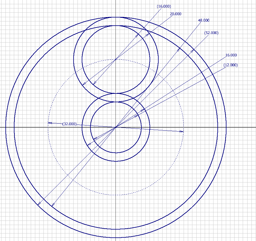
In this example:
Z_s = 12,
Z_p1 = 20,
Z_p2 = 16,
Z_r1 = 52,
Z_r2 = 48.
For the first expression, the result is (1 – (16*52)/(20*48)) / (1 + (52/12)) = 0.025 or 40:1
For the second expression, the result is (1 – (16/20) / 2*(48 / 12) = 0.025, or also 40:1.
Finally, for the third expression, the result is (1 – (16/20) / (2 + (2*(16 + 20)/12)) = 0.025.
So all you really need to pick, if there are no other hard constraints on the ring gear size, the tooth counts of only the sun gear and the two planet gears. However, this is still all assuming just one planetary gear. Clearly, any weird combination of teeth can be done with just one planet, but generally planetary geartains have multiple (minimum 2, usually 3 or 5). In this case, the gear tooth counts would be limited to those which make sense and do not force the teeth to “elastically compensate”. This includes the usual design constraints such as the ring and sun must all share a common denominator that is the number of planets (for a rotationally symmetric box… you can totally fudge it like the Tamiya planetary gearbox’s second stage (yellow gears) and have the gears not totally symmetric – can you unsee it now?!). For two-planet systems, the constraint is pretty loose.
It also turns out that this compound planetary gearbox layout is not the most efficient design possible. The whole concept of relative/differential gearing, and harmonic drives, relies on wedging action and leverage, so they are as a whole not the most efficient possible power transmission method for a given ratio. If the planets are small relative to the ring gears, there is significantly more wedging action under load and the associated loss due to increased sliding friction. This somewhat old school but excellent writeup (Thanks Dale!) explains how efficiency for such a gearbox can be calculated. In fact, the example design doesn’t have a sun gear at all – the power is input directly to the planetary carrier, there is only one planet gear set, and a counterweight on the carrier keeps the system in balance.
This makes me think that 1. The weird bevel gear thing on Wikipedia isn’t crazy after all, just drawn strangely, and 2. The first diagram with the blue carrier stick is entirely wrong, especially because
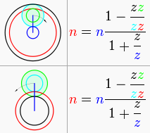
…these two are right next to eachother, and they have the same gear ratio. The fuck is going on?
Anyways, what will I use Wubba Wubba Drive for? Well, it’s already been partially given away by the giant steel serrated knocker thing hanging off the second model. But, before I give more details on what contraption it’s going on, I’m going to design the rest of it first. Stay tuned for more wubbing.


