Revenge of the Quadrotor

I knew I couldn’t leave it for long.

Born of the wreckage of the Deathcopter, kind of like a carbon fiber and superglue phoenix which is not on fire (yet), is a brand new quadrotor! Introducing tinycopter:

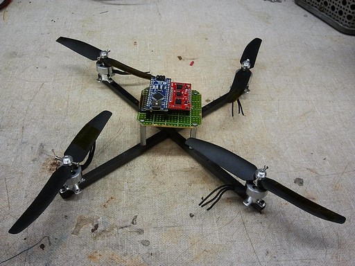
It’s 99% less likely to kill me! Yay!

I pitched this frame together in a little under 4 hours with borrowed 4pcb parts and absolutely no planning beforehand. That means it should work perfectly when I wire everything up.

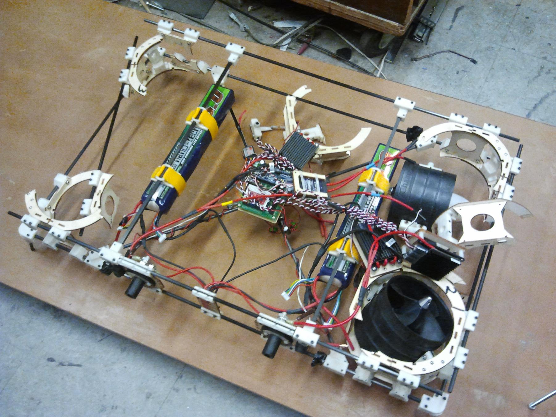
I began the process of scrapping the big frame after determining that using the two battery struts, which are square, would let me build a pretty sturdy combination motor mount and frame. I have still yet to test the two remaining fans – should they prove to be structural, maybe I’ll build something silly and fan powered again (or maybe an Avatar Gunship or something).

The IMU and Arduino Nano were recovered from the 2.007 carrier (which will see service in another vehicle some day) for Tinycopter.

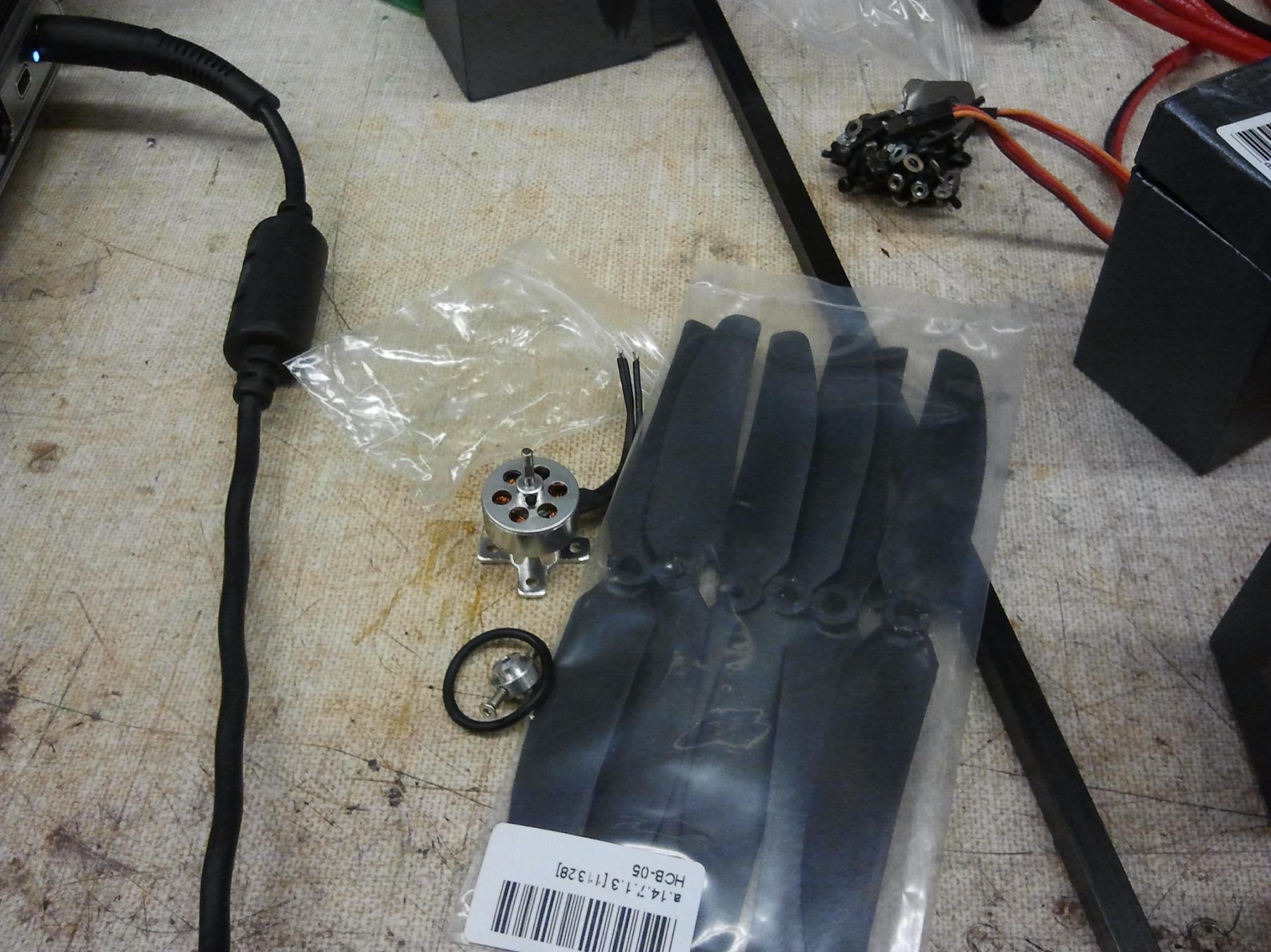
From the mass of quadrotor parts Shane purchased, I’m going to use the Hobbyking 10 gram motors and 5×3 propset (which were too big for 4PCB). Conveniently the 10g motors also have a cross shaped flange base, of which I will use two of the mounting holes.

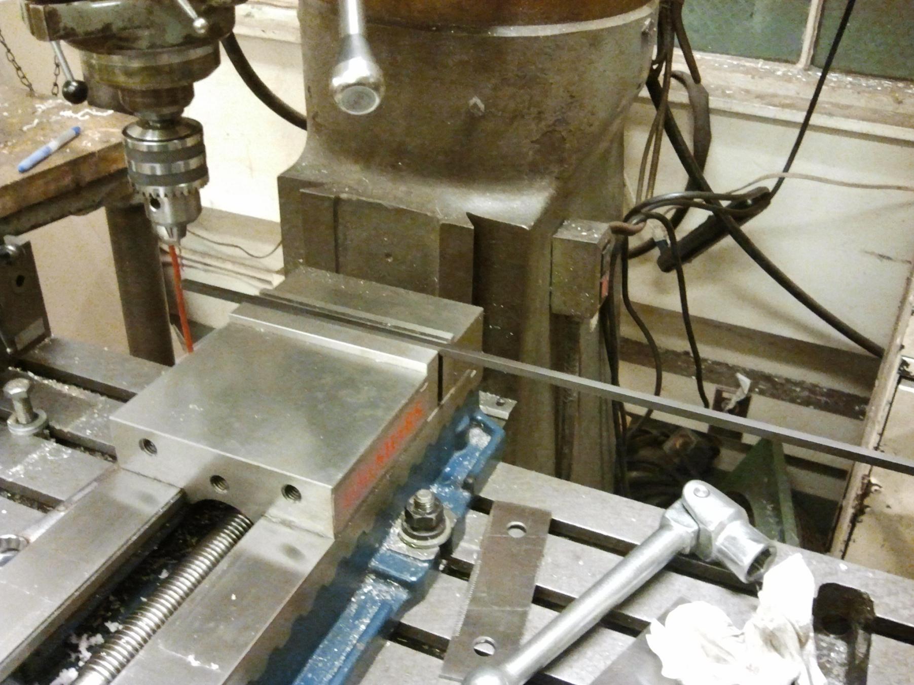
I drew up a quick Solidworks sketch of where the mounting holes should be, and then made both struts in series using the mill’s X axis for positioning.

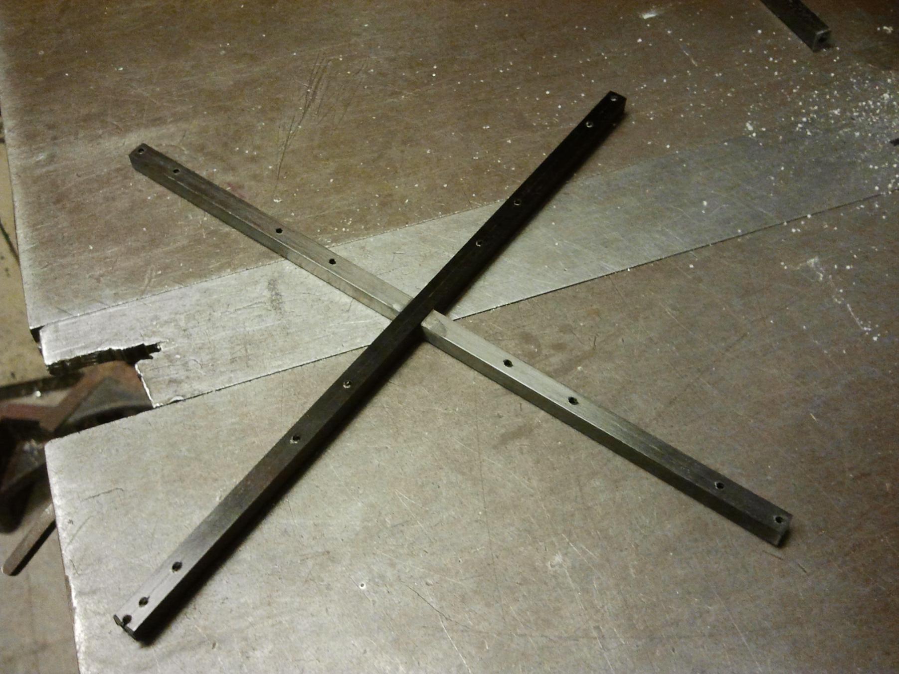
There is a “log cabin” joint (I am completely not sure of what the actual name of this is) in the middle of the carbon fiber rod that I just milled in the same setup. This allows the “X” to have a contiguous flush surface, so I don’t have to make any strangely shaped adapters in the middle. The four sets of holes near the center are for mounting electronics and accessories.

The joint is very tight-fitting, so I wicked some ultra-thin CA into it to keep the struts together.
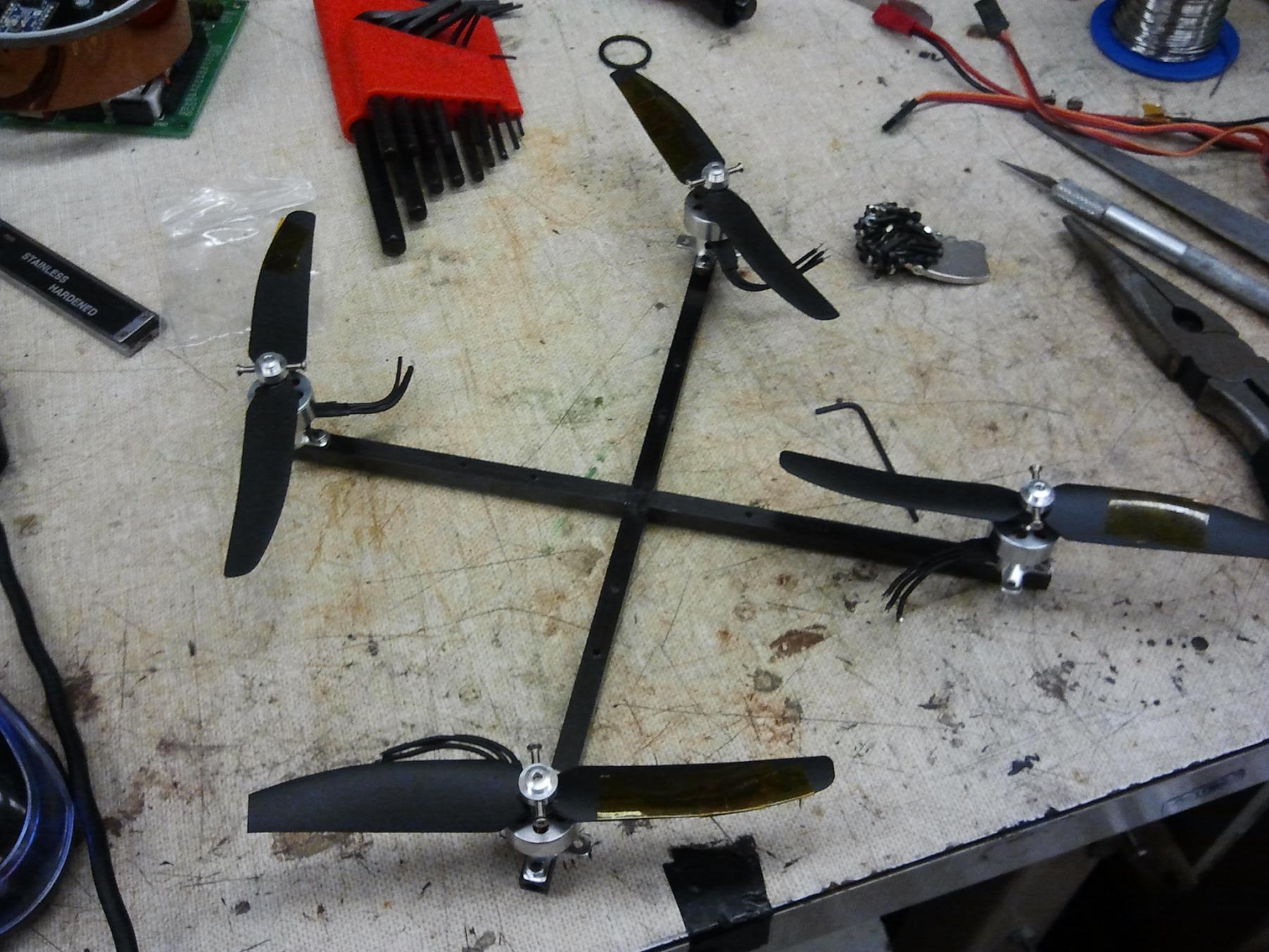
All together!

I spent a few minutes investigating different ways to assemble the 10 gram motors and props. While it comes with a prop saver type hub, it is terrible.

Okay, so the hub itself is pretty okay. The props, however, are garbage. Not only are they totally off balance (kapton tape is visible on them to correct for the imbalance – the worst one needs almost an entire leading edge full of them!), but the hubs are not level – they have sprue bits hanging off them requiring a bit of knifework, and the bore on the correct side of the prop to use with the prop saver is very loose and sloppy. The rubber band that forms the prop saver mechanism is also fairly loose, and I’m not keen on it flying off.

So I turned the whole thing upside down and used the prop saver ring to sandwich the prop against the motor face. Nothing’s being saved any more, but it’s way more solid.

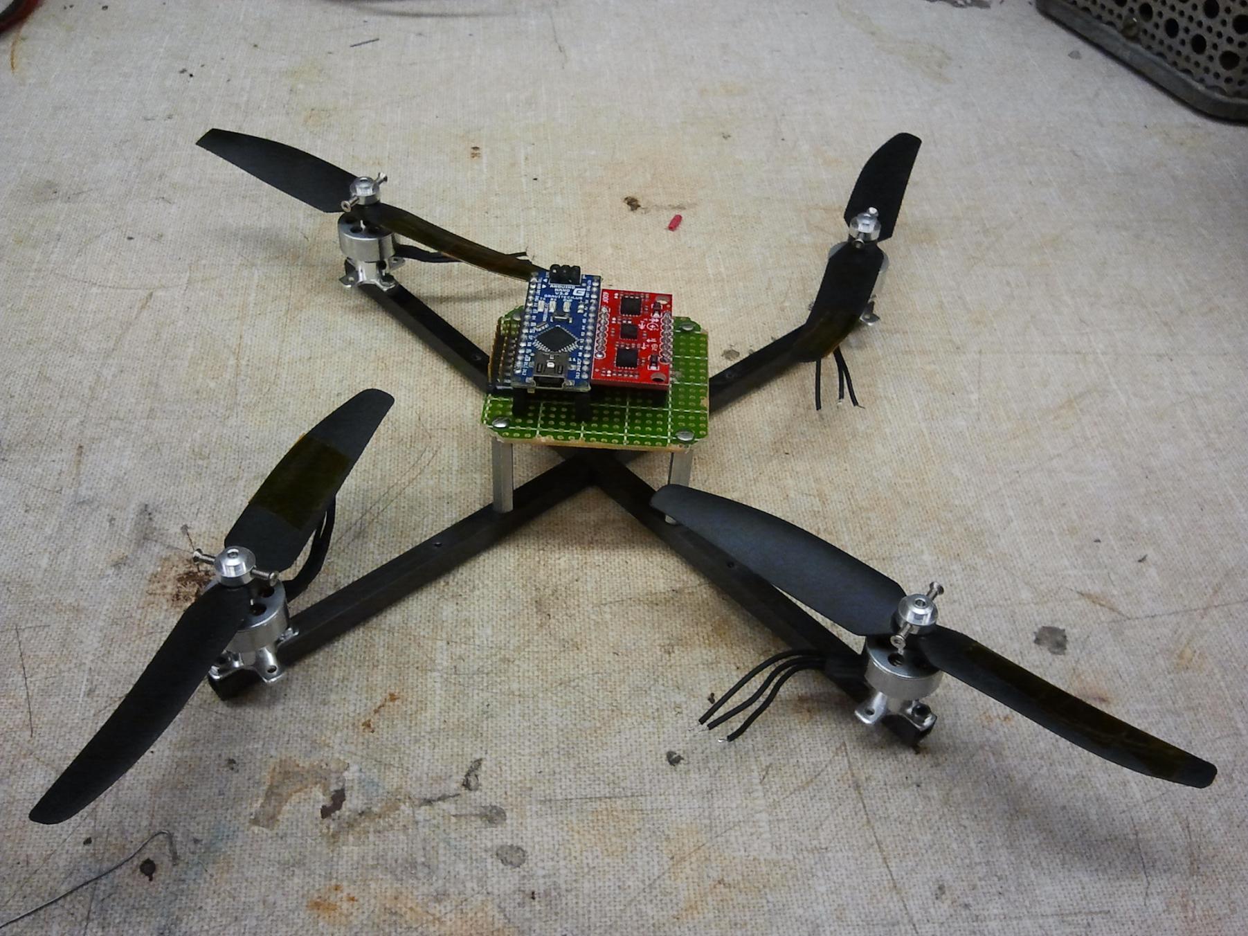
Title image again! I quickly whipped up an electronics mount out of some perfboard. 1″ tall 2-56 standoffs, actually 4pcb’s spare landing gear, make up the electronics mount. The standoffs are flexy-CA-glued to the carbon fiber, since I could not get 2-56 threads to hold in the material. The electronics board will be very simple – just the Nano, the 6 axis Razor IMU, and some headers.  5 volt logic power will be supplied by the motor controllers directly.

I currently do not have a matched set of 4 tiny motor controllers, but they should exist (either found or shipped) by the end of the week. I’m planning on using some 6 or 9 gram controllers from either Hobbyking or equivalents from HobbyPartz, but that’s all contingent if some can be excavated on campus.

The battery will be a 2S or 3S, 480 or 500mAh pack. I was testing with a 3S pack and the motors seemed not to mind, but they produced far more thrust than I feel like was warranted – 100 grams or more per motor. However, I’d have to order 2S packs, since I don’t have any.  The plan is to have the battery, which is the heaviest single part, reside under the electronics deck. This keeps the center of gravity fairly high, and it should almost be inline with the props.

This is fully intentional: Intuition and urban legend both suggest that having a low center of gravity (defined as below the vertical center of thrust of the props) results in a more stable vehicle due to the pendulum effect. This is, however, actually not the case. The pendulum effect actually contributes more strongly to unstable oscillation the lower the center of gravity is. Ideally, the CG should be exactly in plane with the props such that inertial forces do not have a moment arm to affect the system, but this is practically difficult to achieve. In that case, it’s actually better to have it a little high, above the props.

Weird, huh? [1]

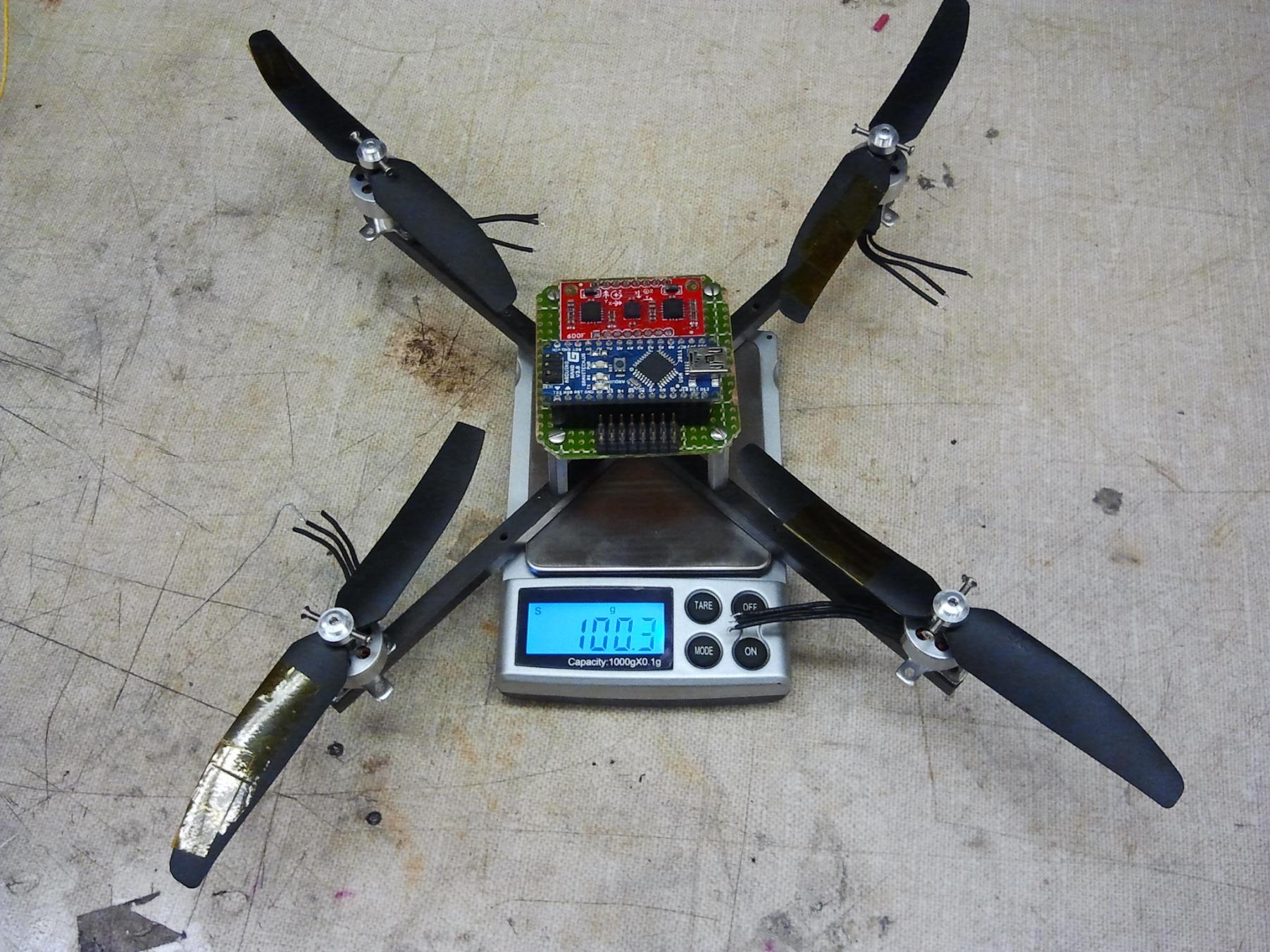
Tinycopter is going to be a bit chunky, since I still can’t grasp the idea that flying things need to be light. Without controllers, battery, receiver, or wiring, it weighs in at 100 grams. The battery should be about 50 grams, the controllers around 30 grams, and the receiver about 9 grams. So, the all-up weight of Tinycopter should be about 200g. I’m sure the battery can get smaller if I go ahead and order some packs (360mAh, 7.4v packs are usually around 30 grams).

Despite me just having sung its praise in the last post, XBypass will not be used on Tinycopter at first. Commenter beak90 has pointed me to the PinChangeInt library in Arduino, so I am going to try first to do that thing I described in the XBypass post with timers and pin change monitoring but without the ass of real software. This means Tinycopter will use a stock radio.

The electronics in Tinycopter have been positioned to use the “box” orientation, which I find a little more intuitive since I can think about it as some kind of flying robot. I’m used to driving robots on the ground, and my transmitter technique is definitely reflective of that. I should be able to make it ‘mode switch’ in software as needed.

Additionally,

No external t-nutting or support equipment yet, but it’s getting there.

In the Interest of Future Flying Objects: XBypass

Despite losing the Spruce Goose of Quadrotors to an unfortunate semi-controlled flight into terrain where I was the terrain (from which I’m still recovering… the square area of skin has recovered by more than 75%), I haven’t quite given up on the prospect of building a flying thing yet – but for now, they will be smaller and more easily batted from the sky. For instance, I’ve figured out why Ballcopter never worked properly. The very last update left it in a state of limbo, which I can sum up in one sentence: No, it didn’t work, but more on that later.

Eventually, Ballcopter was scrapped as its foam structure was slowly eroded away by virtue of existing in MITERS.

But there will be a day.

In the mean time, I wanted to satisfy one of my persistent self-stabilizing-flying-thing itches: how to pass control inputs from a handheld  radio to the flying thing in question without having it process several consecutive servo pulse lengths. For the most common & simplest Arduino-compatible balancing algorithms, this limits the maximum control update frequency to 50hz, since the microcontroller has to actually measure 10 milliseconds of pulse commands (for, say, up to 5 or 6 channels) out of every 20 milliseconds. The remaining time is often taken up by software floating point multiplication and division.

The reason it takes so much of the loop time is because the abomination that is Arduino’s pulseIn() command. It’s a “busy wait” loop that sits and increments a counter while the pulse is being detected. It’s neither interrupt based nor uses the hardware timers (the loop is timed empirically). So while taking in a servo pulsewidth, the microcontroller can literally do nothing else. A little inefficient, in my mind.

More sophisticated ATmega based flight controllers like the Ardupilot use the chip’s hardware timers and internally generated interrupts. For instance, as far as I can tell in the Ardupilot, Timer 1 is constantly running (counting) and overflowing (resetting to count more), and pin change interrupts on the input pins are used to capture snapshots of the counter status, and the resultant pulse width is just the difference between the values when the pin changed from low to high (pulse started) and from high to low again (pulse ended). And if the counter overflowed while the pulse was high, no problem: just add the max possible value of the counter to the pulse width variable and keep counting. Yes, I spent a few hours reading Ardupilot source code to figure that out.

And no, I’m not going to steal it and use it, because it’s written all in straight Atmel C, and so it might as well be gibberish to me. I can read and  understand it, but hell if I’m going to write it.

One method around the onboard servo processing problem is completely bypassing hobby radios as an interface medium, which people often do with joysticks (with or without tethering to a computer). For example, there is the Arbotix Commander, which is essentially an XBee and Arduino in a completely unergonomic, overpriced package which seems to have functionality problems based on a few reports from my peers – I had the displeasure of dealing with the first version personally. Shane tethers his USB Playstation controller to a laptop, but that means the laptop has to be deployed whenever something has to be operated (The upside is infinite debugging and telemetry ability, which a plain R/C radio doesn’t give you).

So really what I would like is the ability to replace the transmitter-air-receiver-servo_pulses interface with something much more direct – like serial over wireless; something that just takes the transmitter inputs and pipes them directly to my vehicle, where it can be buffered and read at will. XBees make the serial over wireless problem very easy to solve. The result would be an XBee using a cheap R/C radio as a brainless “trainer box”: most radios have a “trainer port” over which servo pulses can be sent (over a cable) to a master radio, for situations like when you’re actually training someone who is utterly clueless about flying things (me) and want to take command of the vehicle if anything bad should happen. If this pulsetrain is read and parsed at the transmitter, then I effectively offload the overhead of processing servo pulses from the vehicle – allowing it to process much faster (hundreds or thousands of Hz) and making closed loop control less granular. My inputs would still be updated at 50hz, of course, but I doubt I can react to an event as fast as 0.02 seconds anyway. The vehicle can keep itself stable much faster.

Anyways, that’s exactly what I built. An Arduino Nano, reading the pulsetrain from a transmitter trainer port, and piping the read values as bytes over to an XBee.

It’s not nearly as epic as I made it seem to be, seriously.

I have two cheap 2.4ghz transmitters, one of which I got ages ago for Cold Arbor, and another one I picked up over the summer for Ballcopter. Which really means I have 2 of the same radio. They are both made by FlySky, but the right one is a Hobbyking rebadge. These things cost $28 brand new, with receiver, and some of the consequences of that cheapness show through – for instance, they don’t come with external servo reversing switches like every other radio, but the holes and pads are present internally to use them and if you mount your own switches the functionality is even there in the microcontroller, but no we will absolutely not spent 20 more cents to install those damned switches.  They have a 4-pin mini-DIN (also known as S-Video) connector on the back which is a trainer port.  And as usual with small Chinese gadgets, there is a community devoted to hacking them. It took me all of 10 seconds of Googling to find the pinout of that trainer port.

A little scope probing of pin 1:


The PPM pulsetrain


And zoomed in further.

The biggest difference between this “PPM” signal and the servo-style “PWM” (which isn’t even “PWM” but pulse-duration modulation… which collection of idiots agreed on these terms?) is that

  • It is falling edge driven – the time between falling edges of the square wave is actually the duration of the “PWM” pulse. When the receiver detects one of these falling edges, it will stop outputting the pulse on one channel and immediately start it on the next.
  • As a result, the actual “High” time of the pulse only goes between approx. 600 to 1600 microseconds on my radio
  • The low time is fixed duration at 400us. Makes sense – the minimum pulse lengths on the servo side, then is roughly 1000 to 2000us as it should be.
  • It “idles high” – meaning the gap between signal is +5v.

So I’d have to come up with a way to distinguish a signal pulse from the long idle pulse. Arduino’s pulseIn() doesn’t even allow in-pulse timeouts. It allows pre-detection timeouts, so you don’t wait forever for a pulse if it never comes, but it does not have “hey, this pulse is over the length I care about… let’s move on with life”. I’d have to get around this by throwing away the first update and “syncing” to the rest of the pulses, since I know how many there are and about how long they should be.

The first step of the hardware hacking was disabling the internal radio. As I found out while building the Deathcopter, 2.4ghz radios will tend to step on eachother. I didn’t want to permanently take this radio module out, however. Leaving myself the chance to return this radio to ‘normal’ duty if I ever figured out something better, I just added a pin header connection to the power supply wire. It would be left disconnected when I’m using my hack.

Next was throwing the hardware together on a perfboard. This little arrangement costs way more than the transmitter ($17-34 for an Arduino Nano and $22-25 for an XBee regular 1mW), so I really hope this isn’t the terminal solution. It’s also way underutilizing the Arduino right now, since I only have Tx and Rx pins connected, and one other digital pin hooked up to the PPM output. The transmitter provides 5 volts from the trainer port, so this board has no other power supply.

The XBee is mounted on an Adafruit XBee Adapter.

And that’s it.

Yeah, I didn’t even bother trying to source a 4-miniDIN for this. At least, not until my Digikey order arrives – until then, it’s wires jammed into sockets.

I took a few minutes hours to write the single pin read, serial write software for the Nano. The hard part was, again, thinking my code does one thing but really having it do something different – just logic errors, all caused by having to differentiate the long idle pulse from the servo pulses. But at the end of it:

There we go. I’m only piping back 5 channels out of 6 here, but this was successfully done over the air between 2 XBees. This is all done using Serial.print(), which converts everything to ASCII and thus has unnecessary overhead. When commanding a vehicle, I’d just send the raw byte values because I’m fairly sure my vehicles are not literate.

So how do I test this contraption? With someone elses’s flying object, of course.

4pcb became the subject of a few transmission tests and a whole lot of floor whomping, as seen in the test video:

While not the most economical option, it does work, and it does solve the problem I wanted to solve. I’ll probably look to refine this board or permanently mounting it inside the transmitter, possibly with a plain ATmega chip by itself so I at least don’t have to buy even more Arduini. Otherwise, creating a dongle using Arduino USB host shields and an XBee would open the floor up to using just about any gamepad or joystick as a remote.

The “XBypass” sketche as used on 4pcb is here. The general idea was to wait for the first time the 9ms long timing pulse was received, then immediately start taking in n channels, storing them, and then processing them into single-byte values (for transmission convenience as well as because 4pcb takes such single byte commands).