Überclocker 5.0: In Which I Actually Have to Build the Bot, Not Just Talk About It

Here, have an Überclocker kit. That’s it. My job is done and I’m going home.

Hah – funny story though. The past 3 generations of Uberclocker were actually ALL sold in the end to other builders. That’s right – before this build, I didn’t possess a single one of them. They were sold in various states of disrepair, of course. But sadly, I have yet to see any of them back in the arena, or face my own follies.

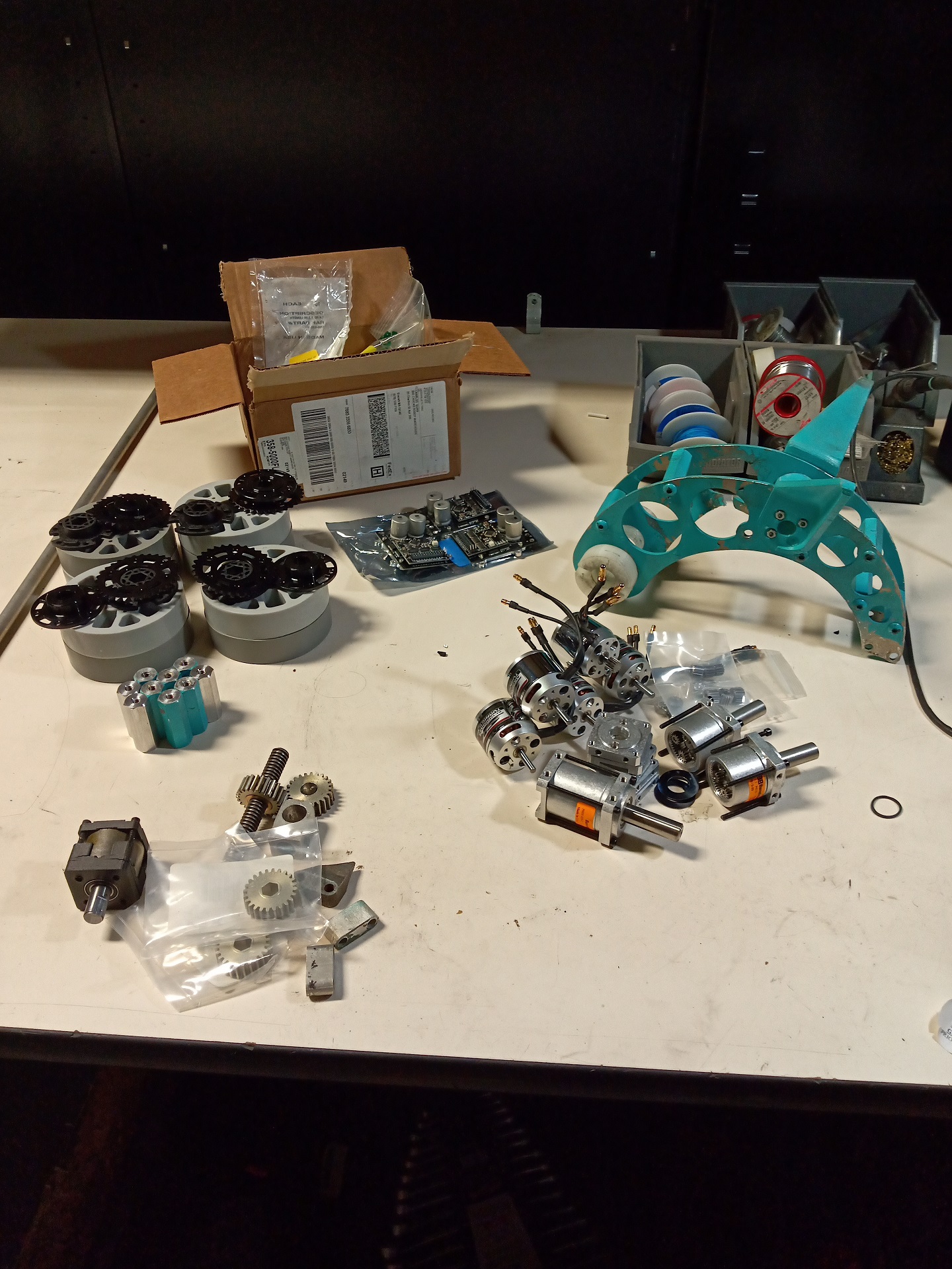
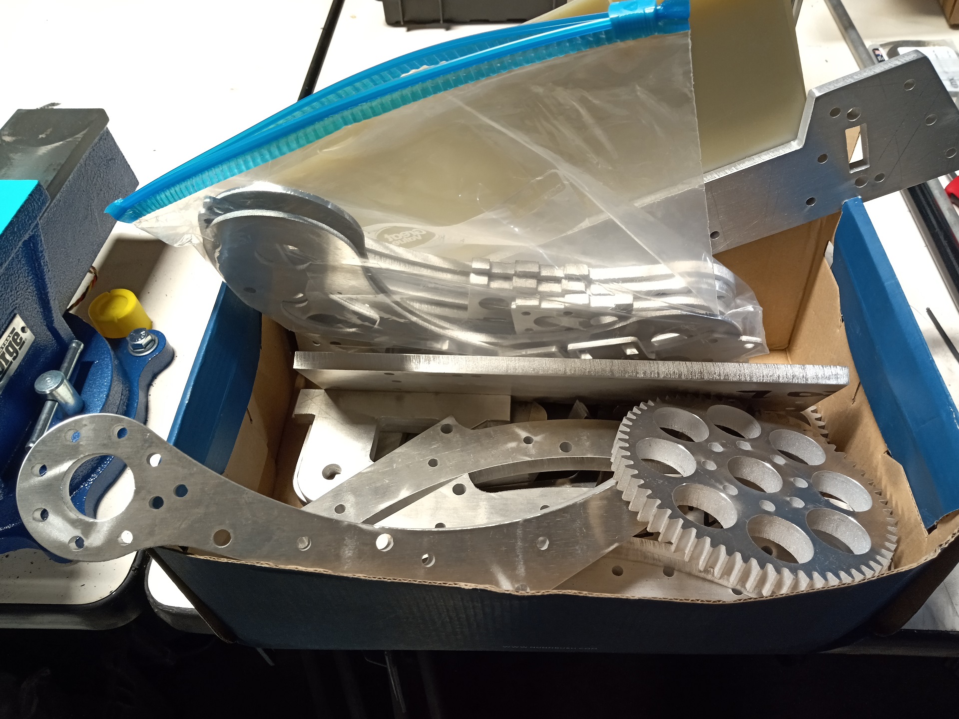
By the last week of September, this was the pile that I’d collected. The last head assembly is just for show – it was a spare made for the previous bot (Uberclocker 4.0) and is damaged in a couple of places. I’d gotten orders in for motors and pulled a couple of other Clocker 4.0 parts out of the organizer. A lot of this will see reuse intentionally.

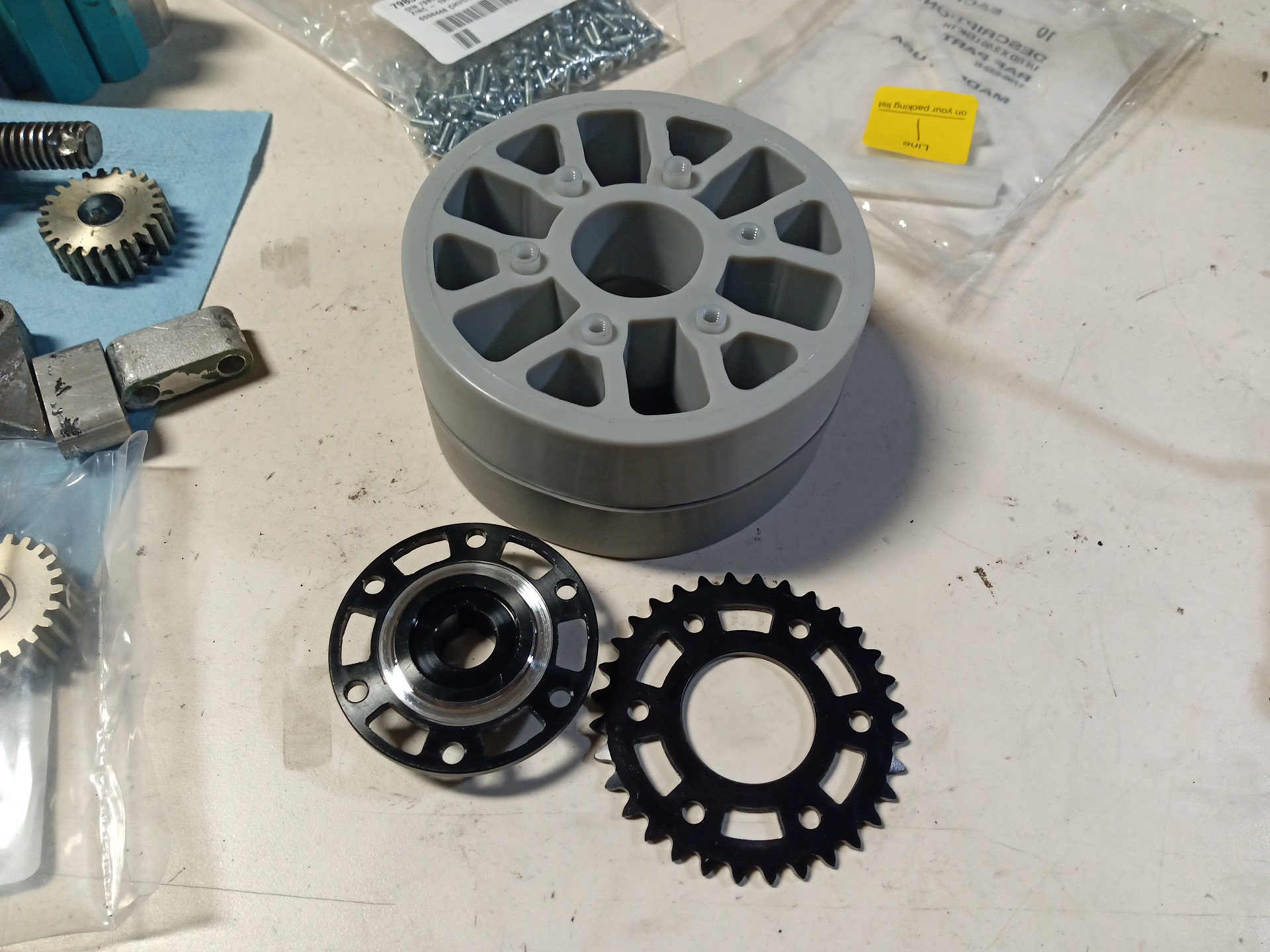
Putting together a wheel assembly revealed that the Vex aluminum Versahub downloadable model is WRONG! It shows up as a flat face on the oberse, but in reality, has a shoulder that is larger than the 1.125″ on the other side. Vex uses 1-1/8″ as the standard because it also happens to be the outer diameter of a Type R8 or FR8 bearing, a very common bearing size.

So I had to turn the short shoulder down to 1.125″ in order for it to actually fit the plate sprocket. No biggie, but hey, update your damn CAD model.

Notice how the wheels are mated together – they have the previously mentioned #8-32 standoffs crammed into them. If I trusted friction enough, there isn’t even a need to have something on the other side. These were rather tough to press through!

One of the plastic Versahubs caps off the outside here. The whole assembly slips on to the P80 keyed shaft and is retained by the shaft’s end-tap screw hole and spacers.

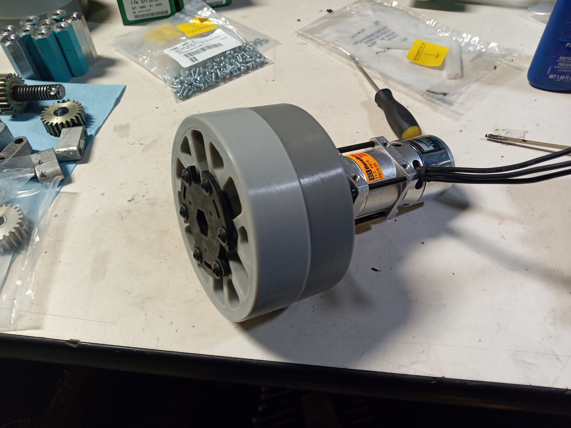
That’s it. What? I made a drive system that’s one gearbox bolted to one wheel? On purpose? Boy, haven’t done that in a while.

The P61 gearboxes assemble almost directly onto the Sk3-4240 motors using the Mabuchi 775 motor mount kit. The shaft is too long by about 6mm however, so I had to trim all of them with a Dremel disc and cleaned up on the belt sander.

I printed off a couple more of these “Angerboxen” as I call them, which have been a staple of my bots for a few years. They’re based on a design I made all the way back in high school (with less tools) and carried through to bots like 12 O’Clocker, and then a spare motor from that made it into Uberclocker v4.

They’re just repackages of generic single speed drill gearboxes into a 1.5″ square profile, compared with their usual 2″ funny shapes. This will be the first time I cram a brushless motor into them, though. For the sake of convenience and expedience, it’s easier to keep this bot all brushless instead of make room for a brushed Ragebridge. Previously, Uberclocker 4.0 had a DeWut for the lift and a 550 size drill motor for the clamp, so it made sense.

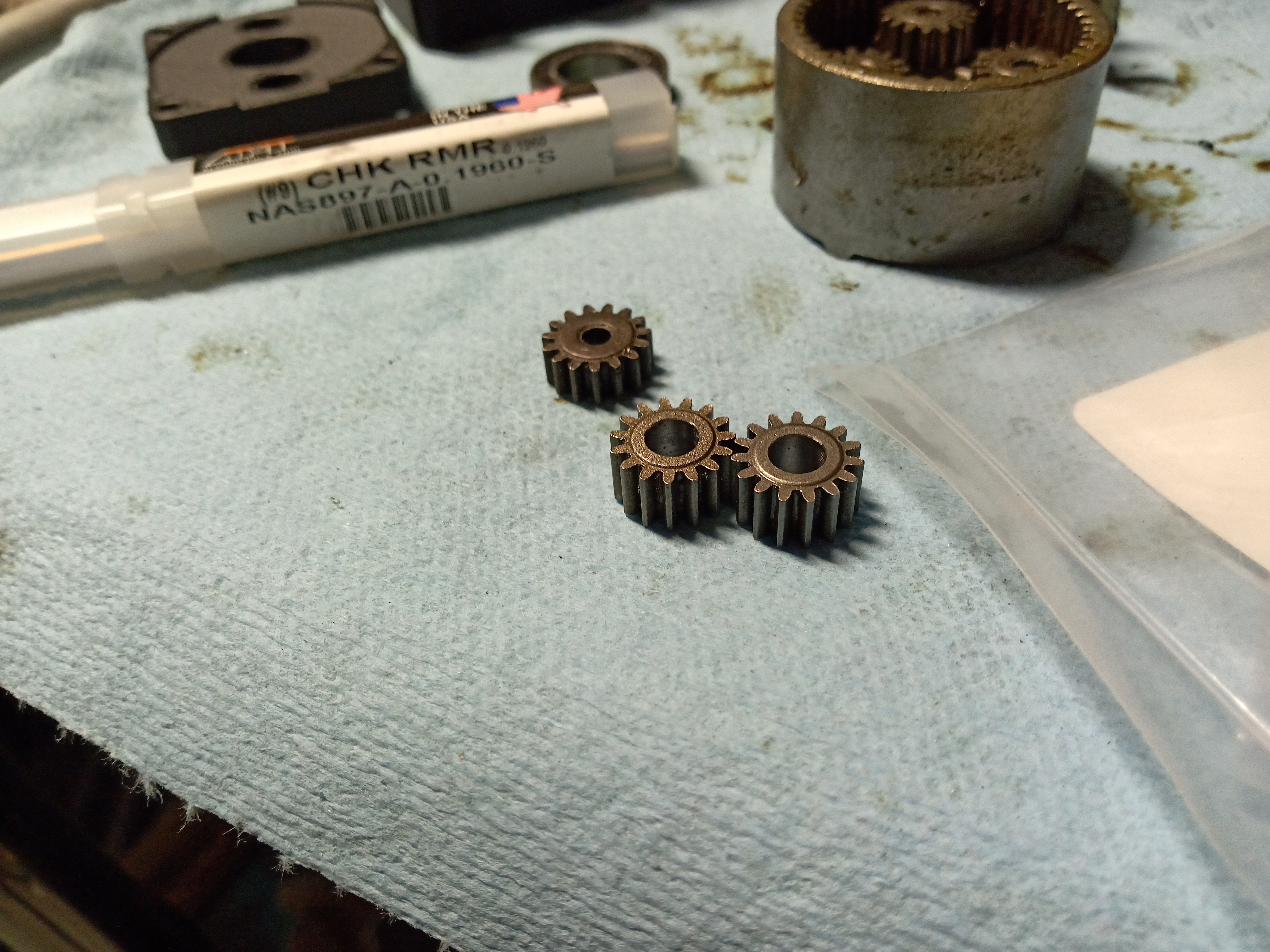
I picked up a 4.95mm reamer to bore out some spare drill pinions (I have a 10 pound bag of loose random cordless drill guts) to turn them into pinions for the SK3 motors.

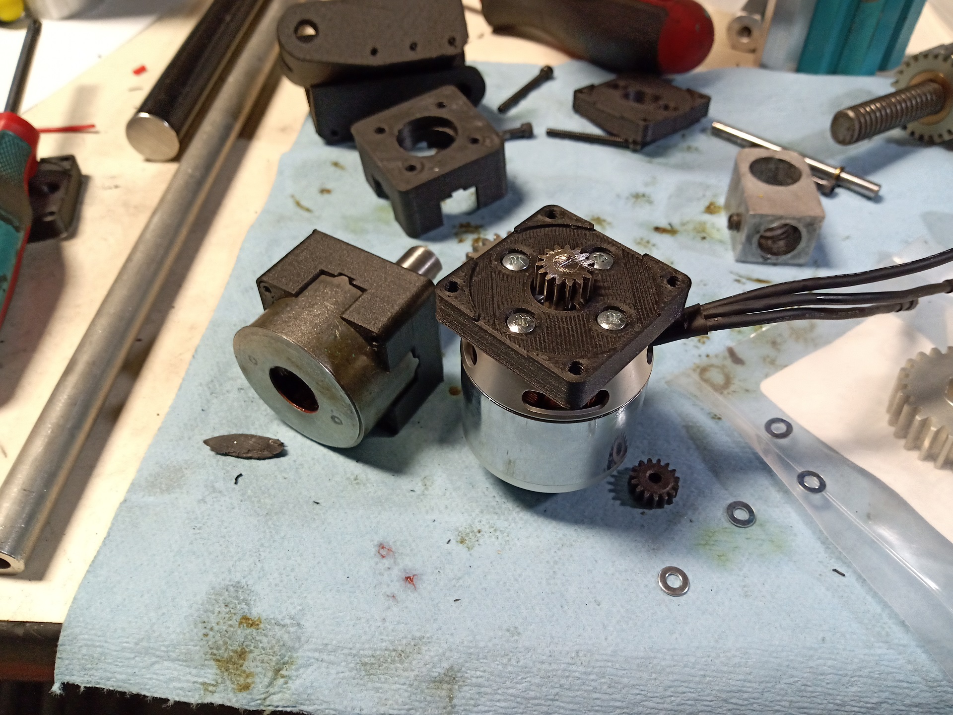
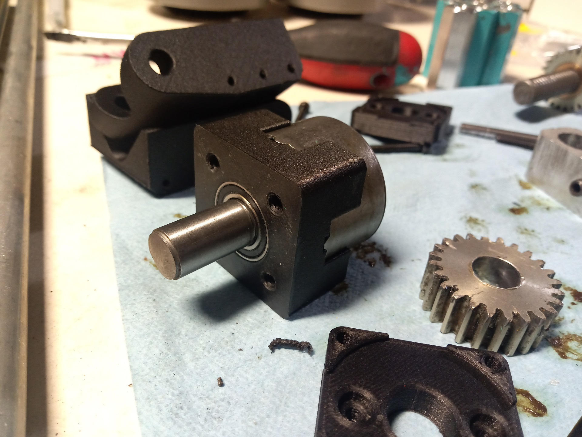
And here it is ready to close up!

…and a day later, after a quick redesign.


You see,  the SK3-42mm motors are bigger in diameter than a 550-size drill motor. Not by much, but by annoyingly enough that I could not feed one of the threaded tie screws in from the motor side.

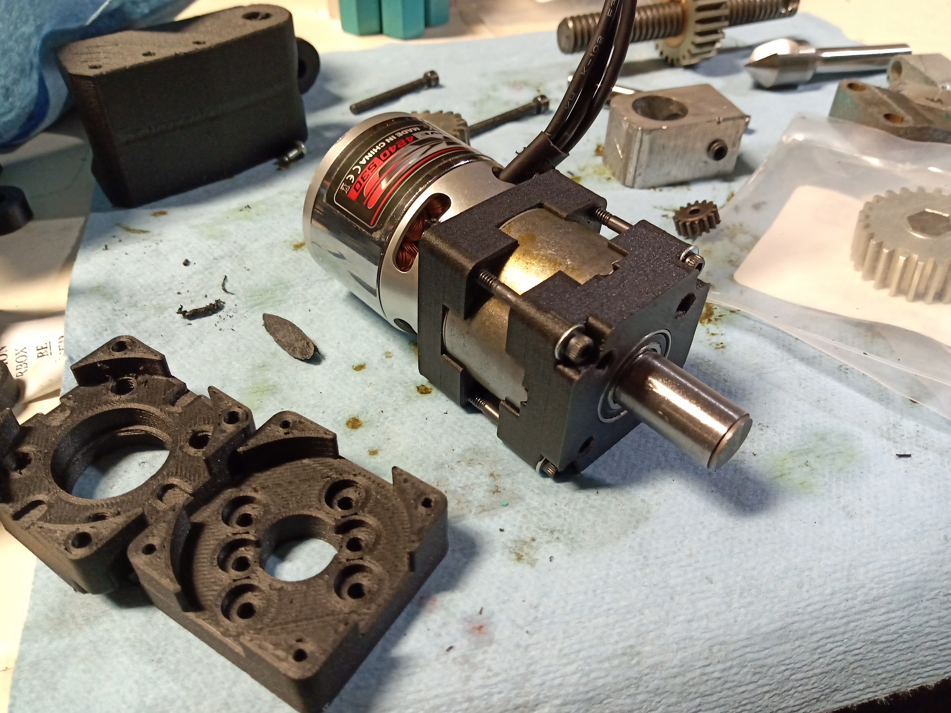
I ended up changing the design up to have the tie rods enter from the front, basically making this an ersatz P60/61 gearbox. I mean, at this point there’s no real need to have a custom design and I might as well do an “embedded P61” like Overhaul had the P80 integrated into the clamp motor. But this setup is lighter and already designed in, and it was easy to replicate.

I added a set of 2 smaller holes in the center for a Mabuchi 400 size motor. This faceplate mount is often found in the smaller 28-30mm brushless motors – if weight got out of control, I could quickly drop the motor weight in half by going to one of them. I don’t need the full power of a 42mm brushless on the clamp arm anyway, but it was there and easy.

All of the subassemblies and components are starting to come together now. If there’s one thing that 1. Building Overhauls and 2. Doing Massive Drone Startups have taught me, it’s always just pipeline spares if you have the materials on hand. You will need them sooner or later, whether gust of wind or gust of Tombstone.

The lift arm shaft, unlike Clocker 4.0, is now a dead axle like Overhaul. I wanted to ensure the less complex box frame had more members to tie it together side to side. Pretty much every Clocker Past has had a live axle to let me easily turn a shaft collar into a torque clutch., but for this one I’m doing it dirty! Shown here are a bunch of spacers to keep the arm elements at the right distance apart. The shaft material is McMaster’s “ceramic coated aluminum” shaft material. Easy to machine, but you have to break the ceramic coating which is actually fairly tough. It will eat regular steel tools, but carbide will defeat it.

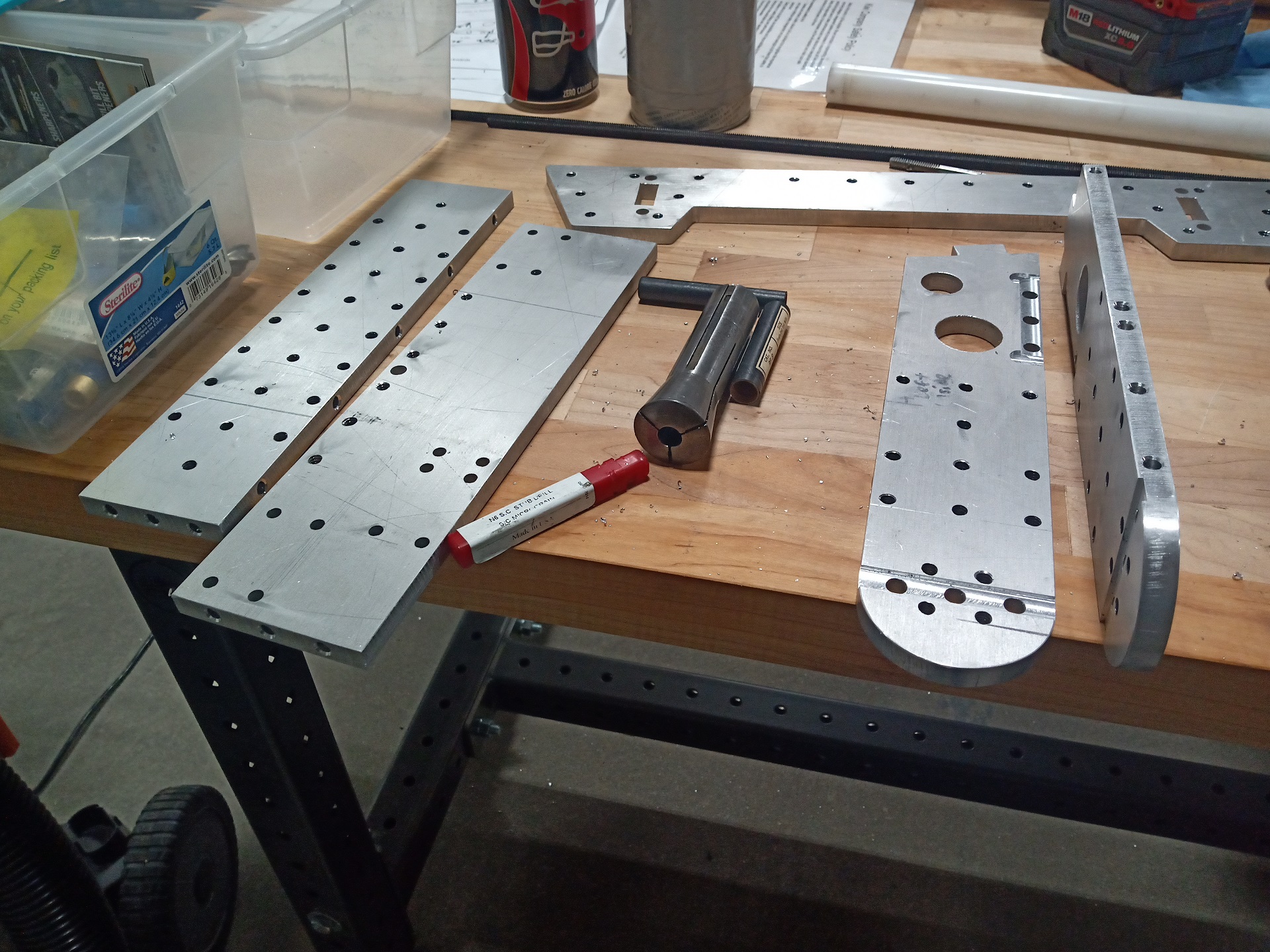
After the first week of October (Well, there goes Franklin Institute), my waterjet parts arrived from a local vendor. I dropped off material the week prior, so an average turnaround time, plus picked up a handful of company parts while I was at it.

This was enough parts for two bots except the frame, which I figured wasn’t going to get trashed at a Sportsman’s Class competition like Robot Ruckus, so I decided to not incur the extra cost and the having to order additional material.  I’ll do this for Motorama instead, where I plan to enter Clocker into the full combat 30s.

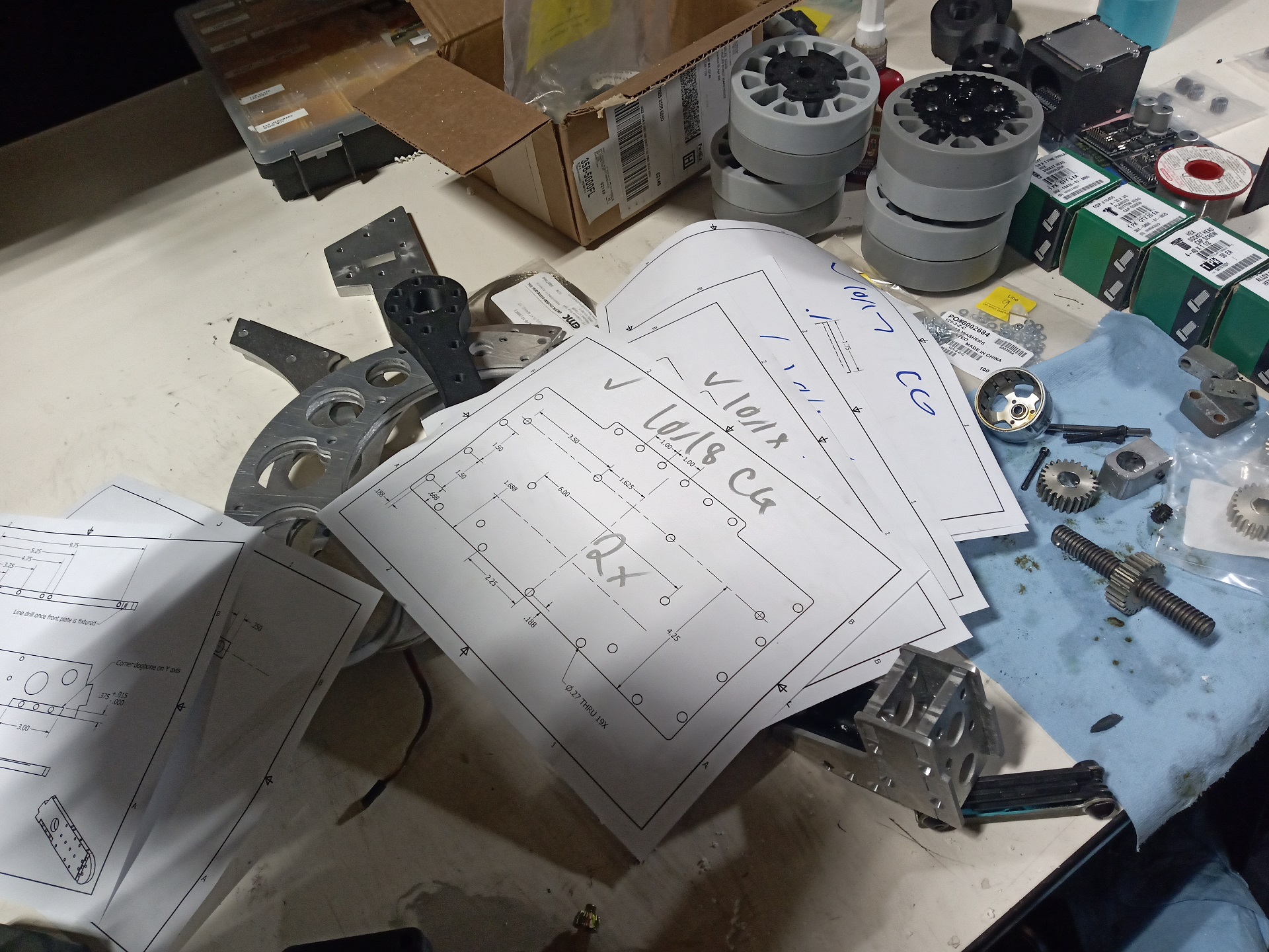
Checking off your own fabrication prints is always satisfying. Maybe just left-over project managment energy in me, but this is definitely my most documented and organized bot in years. Having other people needing to read your thoughts and intentions clearly in mission-critical systems is something I’ve had to get used to in the past 2-3 years, and I most definitely learned a ton from other folks at the company with more extensive industry experience.

(Not to say these are remotely version-trackable and custody-chain verified prints…)

I even back-added the “live edits” into the drawing files and annotated the CAD model. Oh, the horror.


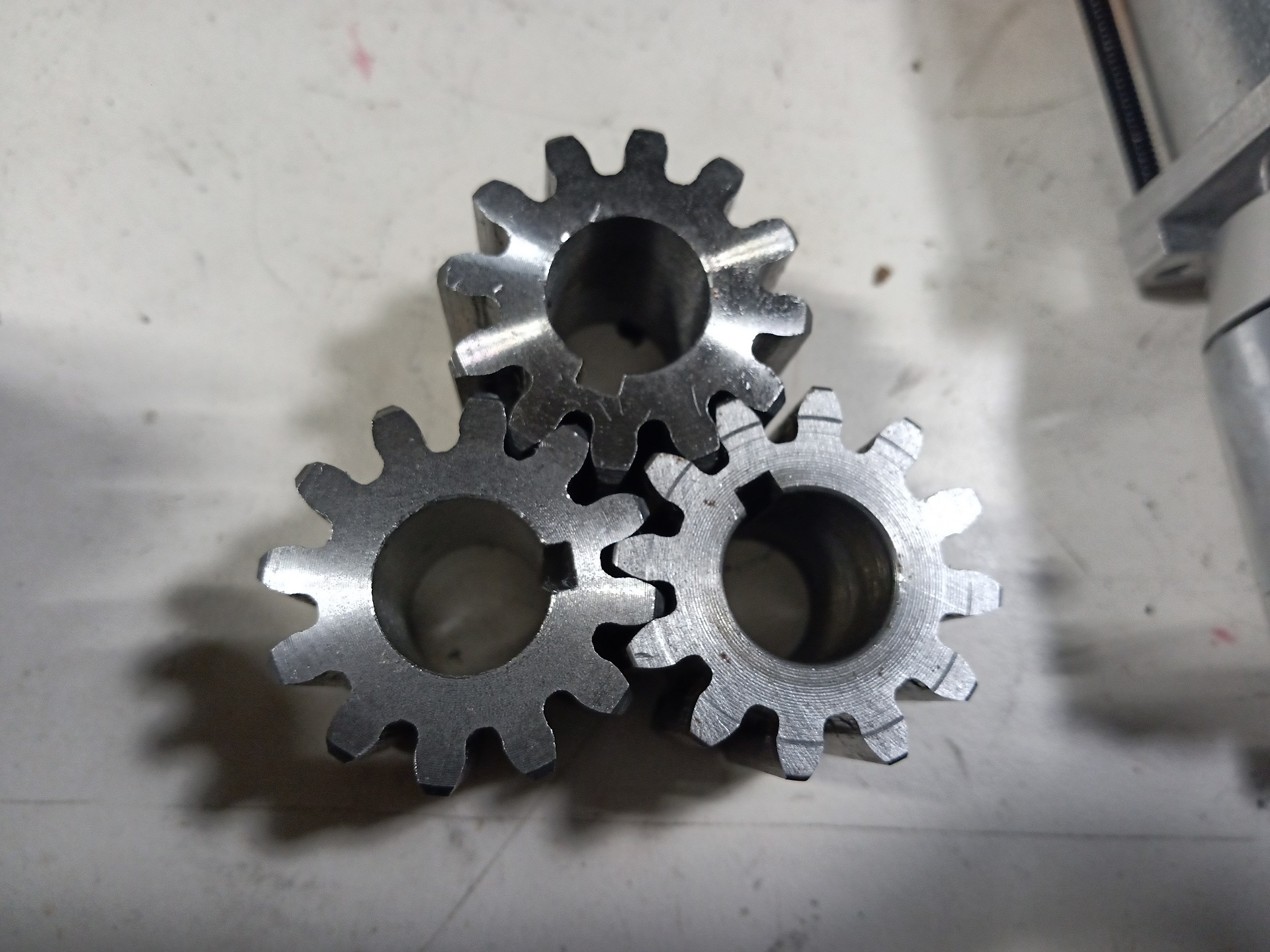
Both Uberclocker and Overhaul make extensive use of these 12 pitch, 12 tooth, 20 degrees P/A stock spur gears. I made a point of just ordering a half dozen and broaching them all, because again, I’ll need these again for OH3.

Anyone ever find it funny when company logos and motivational posters show odd numbers of gears in mutual mesh?

It’s really just a Freudian slip into the culture of the organization.

Machined rear axle spindles and a test fit in a hub. The rear hubs are the same Vex aluminum Versahubs, but bored out on both sides and a type R1212 miniature bearing stuffed into the pockets. They’re retained by a big washer at the end of the spindle so will take more effort to peel off than just ripping out a set of tiny bearings. I could have gone for simplicity and done a Delrin bushing too, but a large overhung load onto the relatively short (5/8″ wide) spindles made me leery about added friction under the bending load of the bot.

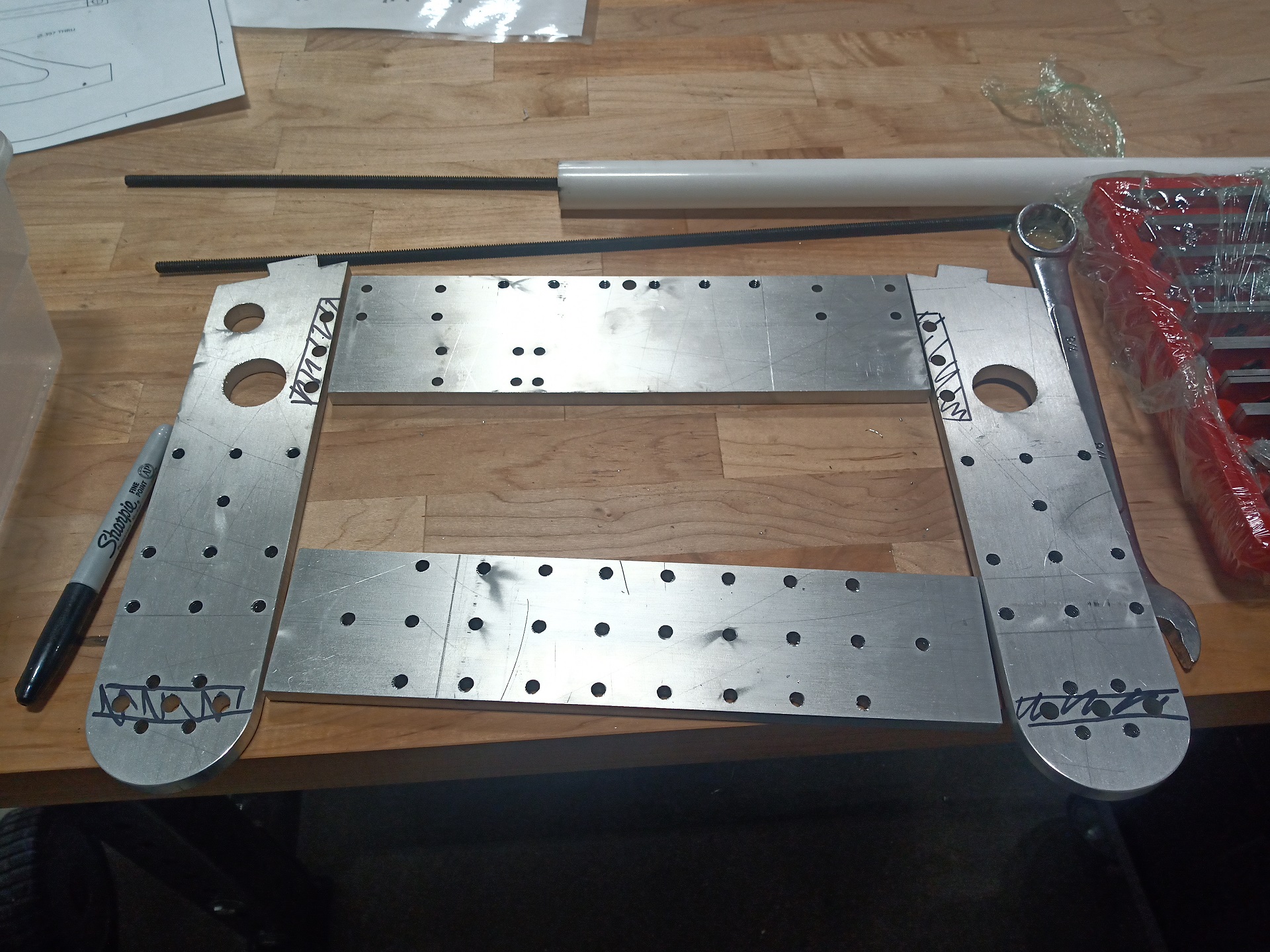
Next up, frame rails that need channelling and pocketing. I knew this was going to end badly for me if I didn’t mark them very clearly.


They also needed the top and bottom plate holes drilled and threaded – I set all of them up at once in the mill with the same reference edge and played a bit of paint-by-numbers on which hole has to go where, making something like the world’s most impractically slow subtractive dot-matrix printer.

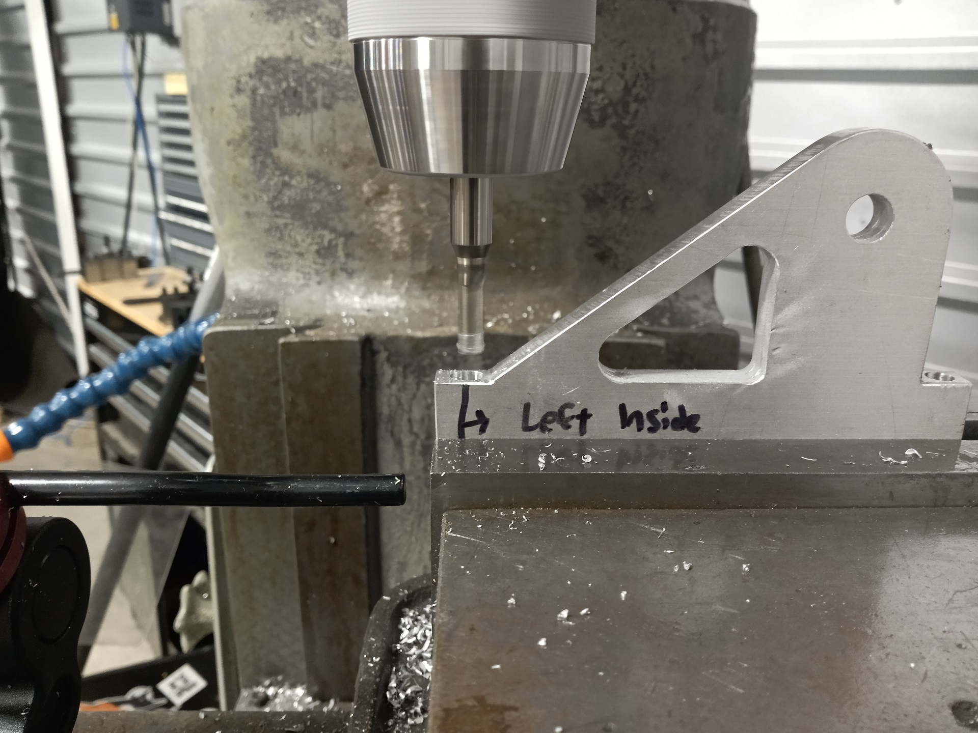
Invitably, I had to bum it up somewhere, and that’s being off by one edge-finder radius on an arm tower. Everyone does this eventually, no matter how veteran! So I had to slot one of the arm towers to let it actually sit where it needed to be.

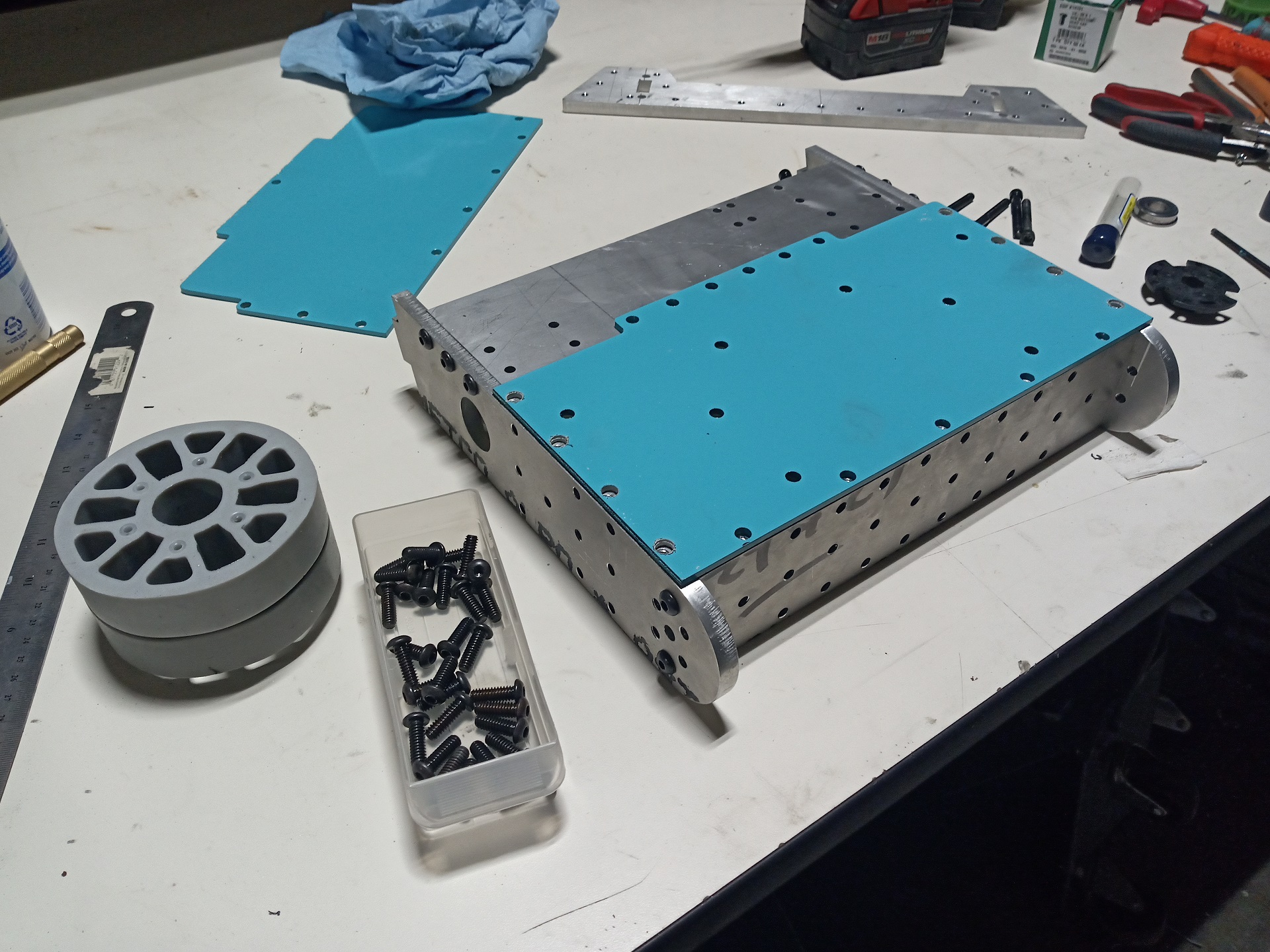
The top and bottom plates are being test fit here. Overall the tolerances were alright, but they do add up, so some of the holes just barely did not align and needed to be step-drilled up a 1/32 in size. I went 1/16″ over as extra future slop insurance.

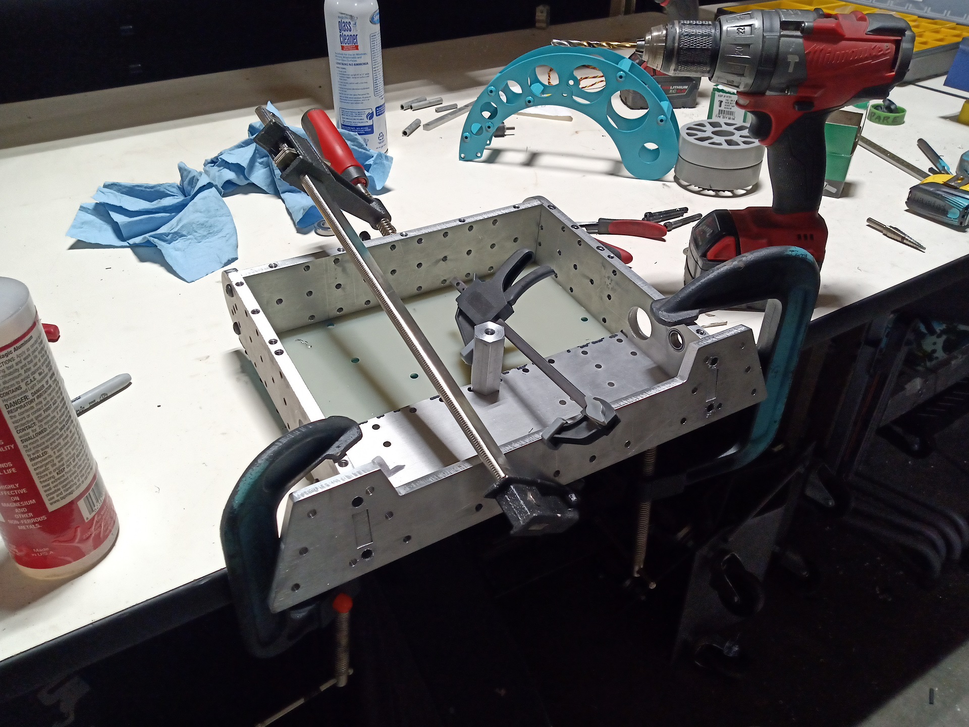
Next, the frame was set up and clamped to the table to perform the drilling / tapping operation of the front bulkhead which was just going to get line-drilled in place. I didn’t feel like tilting the Bridgeport head 15 degrees and doing those coordinate transforms to get to the hole placements this time! Stabbing straight inwards with a drill was going to be all the grace this frame sees.

And that’s it.

The frame’s now fully assembled. 5 parts for the base and 2 for the arm towers. In some ways, this kind of bulky rail construction is elegant in its own right. Clockers Past have had elaborately puzzled together plate frames with part counts that ranged from 15 to 20 or so, and Overhaul carried that over for version 2. It’s now something I aim to move away from for V3.

Next up: Filling in the other parts of it that make it more robot-shaped.

Überclocker 5.0: The Big Post of Designy-Stuff

Alright! So previously I established some of the bot’s principal geometry. Now I had to actually import more components and try to flesh it out, and make little edits here and there. Recall this was where I ended before:

I’d already tabled the idea of moving the clamp motor to the arm tower region, and the lift motor has been moved slightly forward and under the lift gear. This had the side effect of pushing the drive motor (and hence the front wheels) rearward a good half inch or so, and I was a little dubious on if the bot would have weight far enough towards the rear to lift anything.

The clamp arm (the “head” as everyone calls it) was going to stay identical to the previous 30Haul version; I already had parts to fit it, and so it didn’t make too much sense to change. This was, after all, an exercise to see if I could keep a lot of Overhaul 2.x parts the same when it comes to the liftgear. So far, I think I can keep the entire top half of the bot using the same parts, so it will save a ton of redesign effort.

I’m now continuing to flesh out geometry and adding more critical (but blank) parts. The lift gear was going to grow some compared to last 30Haul, to give it more of a ratio with the lift gear. I had a plan this time of running a 3-stage P61 gearbox and using a single larger output stage, in order to be a little more commensurate with the old DeWalt-based lifter which was a 52:1 ratio with a roughly 4:1 output stage. The plan here was for a 45:1 P61 with 5:1 on the main lift gears. The motor shaft would stick through the left frame rail some, so the plan was to put an outboard bearing in to greatly reduce the bending burden that the narrow, necked P6x shaft would have to take otherwise; that’s what the large clearance hole where the lifter gear should go is for.

The intermediate vertical bulkhead from before has been turned into a kind of quasi-bottom-plate made of the same thickness material. All 3 motors bolt to this plate with spacers between them and the plate.

I’ve fully fleshed out the drive system here (all…6 parts of it) and given more detail to the lift assembly, including generation of the arm towers which are hidden in this view.

The Wall of Wub positioning was going to be two large groupings on either side to accommodate the legs Uberclocker is known for (which turned into the wedge pontoons on Overhaul). I also made volume claims for the center shock mounts when 30Haul gets its very own DETHPLOW.

I just imported a 30haul old arm in for geometry and visualization purposes. At this point, the bot’s CG was already very close to exceeding the front wheel line (a.k.a it’ll always tip forward). The height change of the main lift axle meant the forks themselves had to be shorter with a more severe curve. I decided to start over instead of trying to change the geometry of the existing arms, because there was something else I wanted to try.

One of my perceived flaws of the Overhaul lifter fork design is they’re still rather wide at the tips. I wanted the lateral rigidity there, but it did mean if the arm tip got bent up it was hard to get under someone with it ever again.

My bright idea for 30Haul, which would be equally reproducible for Overhaul, is to have a main plate member that is extra thick and rigid, but only have its thickness sticking out as the attack interface. Something set a little more inboard can provide the overall side to side rigidity.

For 30haul, this meant I was actually going to make each fork from a solid backbone of 1/2″ aluminum. We start with the basic dropdown shape which will clear the frame. I made some push and pull adjustments as I went, since I wanted the arms to descend down quickly, but shouldn’t cut away too much of the front frame rail.

The upper curve is generated with some tangent arcs.

And the bottom curve just follows the same arc center with some more edgy features. This is actually how Overhaul 2.x forks were all generated too!

I smoothed things out and added some thru-spacer holes as well as bolt circles.

Check out that arc of 5 holes that runs roughly down the length of the arc shape.  This is what they’re for:

Instead of discrete standoffs like last 30Haul, I’m going to be using a single solid plastic spacer between the inner and outer fork. The discrete spacers were fine for 30lb Sportsman’s Class duty. But they just entered Full Dab mode under any significant side impact since the standoff thru-bolts provided bending axes!

The idea of this fork is the thinner reinforcement plate and the thicker main plate are supported full-contact with the rigid plastic insert. Hopefully, this means it will act substantially like a sandwich composite in that side bending regime, and maybe a hard smack from a weapon will introduce a bend or a bow, but it won’t just completely fold up.

I was planning on using the Markforged machines to print the center spacers in Onyx, but they could also be cut from solid plastic.


After specifying and adding the inter-arm spacers, the majority of the bot’s mechanical needs are done now. Seriously, there’s so little going on compared to one of my average designs.  It’s kind of a refreshing change, honestly.

I next moved onto making the basic support legs that enable the bot to grab and lift. These front legs had to be Sportsman’s Class rules compliant first, which is why I’m going for a simple fork tine-like projection instead of the crazy angled wedges.

I started with the sketch plane that’s defined off the thickness of the rubber shock mounts, and made a big plate which covers all of them.

I had a change of heart at this stage, and instead of making solid projections that altogether ride on the wubbie mounts, I decided to pursue a hinged design.

I always thought I could preload Overhaul’s wedges into the ground with carefully adjusting spacers/washers on the wubbies. Yes, I technically could, but they then weren’t far from a permanent setting anyway. I found that the previous 30Haul only exhibited a narrow range of satisfactory wedging versus propping its own front wheels off the ground.

Hinged wedges have been on the retreat in the sport for a while (albeit slowly) because of their vulnerability to getting damaged. But a lot of bots still sport them, because having something load itself into the ground with its own gravity beats you carefully applying a pre-determined force trying to do the same in an environment that can throw anything at you, at any time.

The legs themselves will be made from thick aluminum also, for this time. They’ll be allowed to hinge upwards about 10 degrees – something can get under them without consequence as long as I back off in time. Even a fixed-but-compliant  wedge would, in that circumstance, still cause the bot to lose traction in the front if lifted.

I just drew some lines that looked cool first and foremost before making the geometry compatible.

Here’s what that assembly looks like up front. Now, it IS true that having hinged elements that are also on wubbie mounts is superfluous, and I agree. If the wubbies proved to add just too much extra compliance, I was satisfied with running plastic spacers underneath for Franklin and Robot Ruckus.

A size comparison between Clockers 4 and 5 (a.k.a first 30haul and new 30haul). The new bot is shorter by a bit – maaaaaaaaaaaaaaybe even too short on the wheelbase. But it’s not outlandishly compact like I worried about going in.

Before I started on the electronics layout, I decided to put the finishing fastening detail touches on the mechanical end – Every hole got at least one sample fastener as a sanity check, and I also laid out top and bottom plate bolt patterns.


Up until this point, I’d actually never designed the rear idler hub. I modeled it as kind of a top-hat shaped spacer with two shoulders, one for the wheel hub bearings and the other to space it out from the frame. It would just get anchored in with an extra-long frame rail screw after the wheel is mounted.  Relatively simple and durable!

I also decided to knock off a few BB entry trends and add “breadboard holes” to the frame. Some on the sides,  as can be seen, but mostly on the back.

The idea of these breadboard holes is to be able to add attachments and defenses in a quick, reasonably strong way. You standardize on your own bolt pattern when designing these accessories. I didn’t have any in mind at the time, but it’s one of those “Boy, it’ll be annoying to drill them later” features.


The clamp actuator was imported from Uberclocker v4 and is almost completely unmodified except for a total height trim right next to the three small mounting holes. There was just a lot of unnecessary material here before, and this allows the actuator to be about as compact as I can get  it.

So that’s about it, mechanically, for the bot. I’m definitely not used to something having this few parts, and I really hope the design approach works for Overhaul proper.

With this allowed to rest for a while, I turned my attention to “things which hold electronics”.

I’m reusing the design of the battery tray from Uberclocker 4 with a few small geometry shifts to accommodate the frame shape of this bot. It has slots underneath where hook-and-loop cinching straps get fed through, which hold the battery down.

The “Rage-hutches” as I call them each hold two 6-FET Brushless Rages face to face stacked vertically. I found this was a convenient height – just barely under the thickness of the frame!  They’re made of 2 pieces each. One is a baseplate with mounting ears, and the other is the perimeter “U” shape with holes and reliefs for the heat sinks.

In another deviation from my usual form that I want to point out is the utter lack of small hardware on the bot now. The top and bottom plates are retained by 1/4″-20 thread size, and even the electronics mounts get 1/4″ compatible clearance holes for a nut-and-bolt interface with the bottom plate.

I’ve tended to use #4 screws – or at least very small screws – to hold ancillary parts and electronics in. One of the critical exercises we did for the company products was really trying to standardize on hardware, and after being part of that, I am keeping in mind the number and types of fasteners in use in the bot. A long time ago, most everything I made robot-wise was just using whatever hardware conveniently fit the geometry…which meant I might have needed 4 different hex wrenches to change a motor, for instance.

Working  on deployable products, plus the much higher regimentation requirements of the BattleBots pits if you actually wanted to get things done fast, have made me think of all this from the start. This bot should be serviceable for the most part with a 5/32″ hex wrench. I actually spec’d button head 1/4-20 (frame and top/bottom plate) but regular socket head #10 screws (motor mounts) because they share the 5/32″ drive. I made more use of #8-32 than I ever have before as my “small screw”, because Vex parts are made for 8-32.

And here’s the size comparison again from the top view. I was fully expecting Uberclocker 5 to not be able to drive without the opponent raised very high. Overhaul 2.x and Uberclocker v4 both have substantial front traction in the form of small wheels located nearer the center of lift. Other things of note – the inner frame rails of Uberclocker 4 are about the same width as the “Outer” ones of v5. The attacking cross-section of the bot remains much the same in terms of width and height. Really it’s those big Vex wheels that sort of make the thing look small, in my mind – the body looks visually smaller in comparison to the large wheels that poke out.

From the side, the bot has gained some height, but pretty much solely due to the added chassis height. I was able to keep the curvature of the fork tips not too severe – the taller they are, the harder it will be to grab opponents.

Overhaul 3 itself should still have a somewhat longer wheelbase and better proportions of the wheelbase x track rectangle. Remember, I had to move the front wheels backwards. By the original design, they should be very close to the front transverse frame rail.

I personally felt, too, the bot could have stood to be a bit longer even here. But, it really couldn’t get longer. Why?

If the bot went further back, the thing wouldn’t really be able to self right. I’m sure it can throw itself back over with the momentum of the lifting assembly, but I like being deterministic from the start. This was a length restriction for Overhaul 2.x also – in one swing of the forks, I had to be able to tip the bot onto its wheels again. So this means Overhaul 3 is going to have to gain wheelbase, If I so desired, by moving the front wheels forward again to where I intended them.

Next up, the initial rounds of fabrication begin!